
Related Manuals for Pfeiffer Vacuum IMR 265


Summary of Contents for Pfeiffer Vacuum IMR 265
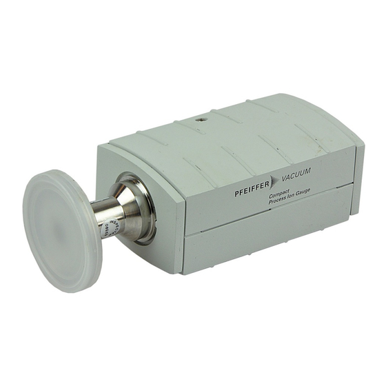
- Page 1 OPERATING INSTRUCTIONS Translation of the original instructions IMR 265 Compact Process Ion Gauge...
-
Page 2: Product Identification
It must not be used for measuring flammable or combustible gases in mixtures containing oxidants (e.g. atmospheric oxygen) within the explosion range. The gauge is a part of the Pfeiffer Vacuum Compact Gauge family and can be operated in connection with a Pfeiffer Vacuum measurement and control unit for Compact Gauges or with another control device. -
Page 3: Table Of Contents
Conversion Table for Pressure Units Relationship Output Signal – Pressure Gas Type Dependence For cross-references within this document, the symbol (→ XY) is used, for cross- references to other documents, the symbol (→ [Z]). BG 5172 BEN / B (2017-02) IMR 265... -
Page 4: Safety
Communicate the safety instructions to all other users. 1.4 Liability and Warranty Pfeiffer Vacuum assumes no liability and the warranty becomes null and void if the end-user or third parties • disregard the information in this document •... -
Page 5: Technical Data
1 … 3×10 ATM (<ATM> button) via <ATM> button (keep button de- pressed for at least 5 seconds) at at- mospheric pressure Hot cathode calibration setting with 16 position switch according to label Supply BG 5172 BEN / B (2017-02) IMR 265... - Page 6 500 kPa (absolute), (only for inert gases and temperatures <100 °C) Pfeiffer vacuum measurement and control units for Compact Gauges fulfill these requirements. The minimum voltage of the power supply must be increased proportionally to the length of the sensor cable.
- Page 7 ≤85% (no condensation) indoors only altitude up to 2000 m NN Degree of protection IP 30 Dimensions [mm] DN 16 ISO-KF flange and 3/4" tube Rohr 3/4" DN 16 KF Weight ≈285 g BG 5172 BEN / B (2017-02) IMR 265...
- Page 8 DN 25 ISO-KF and DN 40 ISO-KF flange DN 25 KF DN 40 KF Weight ≈315 g DN 16 CF-F and DN 40 CF-F flange DN 16 CF-F DN 40 CF-F Weight ≈300 … 550 g BG 5172 BEN / B (2017-02) IMR 265...
-
Page 9: Installation
(→ 11). • The sensor can be baked out at up to 150 °C. For temperatures above 50 °C the electronics unit must be removed (→ 11). BG 5172 BEN / B (2017-02) IMR 265... - Page 10 Establish the flange connection. Install the gauge in such a way that there is sufficient clearance for adjust- ment (→ 16, 18, 19). BG 5172 BEN / B (2017-02) IMR 265...
-
Page 11: Removing And Installing The Electronics Unit
Place the electronics unit on the sensor (3) (be careful to correctly position the pins and the guide notch (4)). b) Slide the electronics unit up to the mechanical stop and lock it with the hexagon socket set screw (1). BG 5172 BEN / B (2017-02) IMR 265... -
Page 12: Power Connection
3.2 Power Connection 3.2.1 Use With a Measurement If the gauge is used with a and Control Unit for Pfeiffer Vacuum measurement and control unit for Compact Compact Gauges Gauges, a corresponding sensor cable is required (→ 23). •... - Page 13 Plug in the connector. Secure the connector on the gauge with the screw (tightening torque ≤0.2 Nm). Connect the other end of the cable to the control device. BG 5172 BEN / B (2017-02) IMR 265...
-
Page 14: Operation
Allow for a stabilizing time of approx. 10 min. Once the gauge has been switched on, permanently leave it on irrespective of the pressure. 4.1 Measuring Principle, The IMR 265 consists of two separate measuring systems (high pressure (HP) hot cathode and Pirani). Measuring Behavior... - Page 15 Figure 2 The bridge voltage U is a measure for the gas pressure and is further processed electronically (linearization, digitizing). Measuring range The IMR 265 covers the measuring range 2×10 ... 1000 hPa. Switching threshold Hot cathode HP Pirani 2 × 10 1000 hPa 5 ×...
- Page 16 Selecting the setpoint The IMR 265 has five definable switching thresholds. It is thus possible to prevent the switching range from being situated within the process pressure range. The –2 factory setting of the threshold is 5×10 hPa. Another setpoint can be selected via the <P ↔...
-
Page 17: Operational Principle Of The Gauge
The baffle and the closed internal design of the measuring system as well as the heat generated by the measuring system contribute to this. The IMR 265 is factory-adjusted in such a way that the hot cathode is switched on –2 at ≈5×10... -
Page 18: Maintenance
30 minutes is to be expected (gauge temperature = ambient temperature).. Insert the pin through the opening marked <ATM> and push the button inside for at least 5 s. BG 5172 BEN / B (2017-02) IMR 265... -
Page 19: Adjusting The Calibration Setting Of The Hot Cathode System
A slightly damp cloth normally suffices for cleaning the outside of the gauge. Do not use any aggressive or scouring cleaning agents. Caution Make sure that no liquids get inside the product. Allow the gauge to dry thoroughly before putting it into operation again. BG 5172 BEN / B (2017-02) IMR 265... -
Page 20: Replacing The Baffle
Carefully remove the baffle with the screw driver. b) Carefully place the new baffle on the sensor opening. c) Using a stick, carefully press the baffle down in the middle until it catches. BG 5172 BEN / B (2017-02) IMR 265... -
Page 21: Replacing The Sensor
Electronics unit not cor- Check connection rectly mounted on sensor In case of an error, it may be helpful to first turn the supply voltage off and on again after 5 s. BG 5172 BEN / B (2017-02) IMR 265... -
Page 22: Deinstallation
When handling vacuum components, take appropriate measures to ensure cleanliness and prevent damages. Procedure Vent the vacuum system. Take gauge out of operation. Unplug connection cable. Remove gauge from the vacuum system. BG 5172 BEN / B (2017-02) IMR 265... -
Page 23: Returning The Product
Contaminated products (e.g. radioactive, toxic, caustic or micro- biological hazard) can be detrimental to health and environment. Products returned to Pfeiffer Vacuum should preferably be free of harmful substances. Adhere to the forwarding regulations of all in- volved countries and forwarding companies and enclose a duly com- pleted declaration of contamination Form under www.pfeiffer-vacuum.com... -
Page 24: Spare Parts
• description and ordering number according to the spare parts list Ordering number Sensor IMR 265, DN 25 ISO-KF flange PT 120 111–T (Allen wrench included) Sensor IMR 265, DN 40 ISO-KF flange PT 120 112–T... -
Page 25: Appendix
8.50 V ≤ U ≤ 9.75 V Conversion curve Pressure p [hPa] 1E+03 1E+02 1E+01 1E+00 1E–01 1E–02 1E–03 1E–04 1E–05 1E–06 0.0 0.5 1.0 1.5 10.0 10.2 Measuring signal U [V] BG 5172 BEN / B (2017-02) IMR 265... -
Page 26: C: Gas Type Dependence
For gases other than air, the pressure can be determined by means of a simple HP hot cathode measuring conversion formula: range = C × indicated pressure where Gas type Air (N These conversion factors are mean values. BG 5172 BEN / B (2017-02) IMR 265... - Page 27 4 6 8 4 6 8 4 6 8 (hPa) Caution A mixture of gases and vapors is often involved. In this case, accurate determination is only possible with a partial-pressure measuring in- strument. BG 5172 BEN / B (2017-02) IMR 265...
- Page 28 VACUUM SOLUTIONS FROM A SINGLE SOURCE Pfeiffer Vacuum stands for innovative and custom vacuum solutions worldwide, technological perfection, competent advice and reliable service. COMPLETE RANGE OF PRODUCTS From a single component to complex systems: We are the only supplier of vacuum technology that provides a complete product portfolio.
Need help?
Do you have a question about the IMR 265 and is the answer not in the manual?
Questions and answers