Table of Contents
Advertisement
Quick Links
Advertisement
Table of Contents

Related Manuals for Pfeiffer Vacuum DPG 109


Summary of Contents for Pfeiffer Vacuum DPG 109
- Page 1 Operating Instructions DPG 109 Controller PG 0005 BEN/F (1102)
-
Page 2: Table Of Contents
Index Page Safety Instructions..............3 1.1. For Your Orientation.....................4 Understanding The DPG 109 ............5 2.1. Main Features .....................5 Proper Use ......................6 Improper Use ..................... 6 2.2. The Delivery Content ..................6 Installation .................. 7 3.1. Preparations For Installation................7 3.2. -
Page 3: Safety Instructions
Validity These operating instructions describe the installation and operation of the Digital Vacuum Measurement And Control Unit DPG 109 with the article number PT G15 010. The article number appears on the rating plate. To ensure the avoidance of possible product identification errors in any correspondence with Pfeiffer Vacuum please always state the article number appearing on the rating plate. -
Page 4: For Your Orientation
1.1. For Your Orientation Abbreviations used: HPT = Digital Pirani/Bayard-Alpert Transmitter CPT = Digital Piezo Transmitter RPT = Digital Piezo/Pirani Transmitter PPT = Digital Pirani Transmitter MPT = Digital Pirani/Cold Cathode Transmitter DPG = Controller DPS = Power Supply = Cold Cathode Working instructions in the text, ➡... -
Page 5: Understanding The Dpg 109
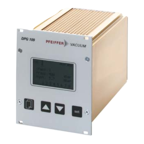
2. Understanding The DPG 109 2.1. Main Features Front Panel DPG 109 Display for DPG109 - Pressure measurement values - Switch threshholds, hysteresis - Units of measurement - Relay preselection etc. Menu key Set key Up/Down key D-35614 Asslar DPG 109 Mod.:... -
Page 6: Proper Use
Proper Use The DPG 109, in conjunction with the DigiLine Vacuum Transmitters, to measure and control total pressures. The unit is ready for connection to up to 9 transmitters of Type CPT 100, RPT 100, PPT 100, HPT 100 und MPT 100. -
Page 7: Installation
Do not carry out any unauthorized conversions or modifications on the unit. WARNING Before connecting to local mains power: The voltage stated on the rating plate of the DPG 109 must comply with local mains voltage values. Only use this controller where the: Temperature is in the range: +5°C - +40°C. -
Page 8: Transmitter Connection
Set the address selection switch on the transmitter rating plate to the desired PLEASE NOTE address 1 to 9 (RS485); for each sensor a different address. Connect to the DPG 109 a maximum of 9 digital total pressure transmitters of the DigiLine Program (thereof a maximum of 4 HPT100). Connection overview... -
Page 9: Pc Connection (Rs 232)
Connecting The Transmitter: ➡ Connect the first transmitter using a suitable data cable (Type PT 348 4xx; Bus cable) o the unit socket ("Gauge"); always connect the double plug of the bus cable onto the transmitter. ➡ Connect the second transmitter with a second bus cable onto the double plug of the first transmitter;... -
Page 10: Relay Output
3.2.4 Relay Output This output is used for the external control of the switching functions of the DPG 109. For this purpose eight relay switchpoints (polarized contacts) are available. Use the mating plug which is provided. Connect and disconnect the plug only in CAUTION a voltage free condition. -
Page 11: Operations
PRESSURE The DPG 109 can be switched off in any operations mode. The keyboard lock is activated (indicated 1005 with a lock sign) until the DPG 109 is swit- ched off. mbar rel.: 2 3 4 5 6 7 8... -
Page 12: Switching On The Unit
4.3. Measuring Mode In the measuring mode the DPG 109 shows the currently measured pressure of the transmitter which is connected. Depending on the pressure range, the display is represented either numerically or exponentially. The switch outputs are controlled according to the set switching parameters and actual pres- sure. - Page 13 »SENSOR MENU« SENSOR MENU Here is displayed the specific sensor data (type of transmitter, sensor setup and the switching values of the combi transmitters) type: HPT 100 of the current channel. BAFil: The function »degas« is only possible on total pressure transmitters using the hot SWMode: trans_HI cathode measuring system.
-
Page 14: General Procedure For Parametering
4.5 General Procedure For Parametering As described in section 4.4. five basic menus are available for parametering. The following example will show how to operate the various commands and keys: “Menu“ key: Switching over to the next menu (see section 4.4.) rel: .. -
Page 15: Menu "Pressure
4.5.1 Menu «PRESSURE« In the »PRESSURE« menu the DPG 109 shows the currently measured pressure of the transmitter which is connected. The switching outputs are controlled according to the set switching parameters and the current pressure. As illustrated below, there are 3 different types of display for the representation of the measu- rement values (see section 4.5.4 Menu »COMMON MENU«/»display type«):... - Page 16 3) The data line between the DPG 109 and 5 6 7 8 rel.: transmitter is not correctly connected or is faulty. 4) The unit serial interface in the DPG 109 is PRESSURE defective. ur/or »ur/or«: The measured pressure is outside the measurement range of the transmitter.
-
Page 17: Menu "Channel Menu
4.5.2 Menu «CHANNEL MENU« This menu shows specific data for the selected channel (transmitter type, gas type and correction factor). In addition the function »adjust« is selectable for the respective sensor. -
Page 18: Gas Type Correction Factor "Channel Menu
Gas Type Correction Factor «CHANNEL MENU« On total pressure transmitters (PPT 100, RPT 100) which employ a measuring method which is independent of the type of gas, o o n n e e correction factor for matching to various gases can be assigned to the transmitter. -
Page 19: Retro-Adjustment "Channel Menu
Retro-Adjustment «CHANNEL MENU« With the help of the DPG 109 retro-adjustment can be carried out on the transmitter. When carrying out a zero point equalization ensure that the pressure in the vacuum chamber is at least one decade below the measuring range of the transmitter. -
Page 20: Menu "Channel Menu
4.5.3 Menu «SENSOR MENU« Type dependant functions of the combi transmitters RPT 100, HPT 100 and MPT 100 can be selected in this menu; described by the example HPT 100. ➡ Depress the “set“ key in "SENSOR MENU" SENSOR MENU until the cursor in the menu point »BAFil«... -
Page 21: Degassing "Channel Menu
Degassing «CHANNEL MENU« With total pressure transmitters employing the hot cathode measurement system (HPT 100) it may be necessary to bake out the sensor anode in ultra high vacuum in order to clean the adsorbed gas particles and thereby to minimize transmitter head degassification. Degas reduces the service life of the filament and therefore should not be activated too often. -
Page 22: Menu "Relay Menu
4.5.5 RELAY MENÜ The relay outputs on the DPG 109 are contolled via variable threshhold values with relevant hysteresis which have to be input, see illustration: + hysteresis threshhold value - hysteresis switch function "off" "off" "on" rel:Relay number rel:... - Page 23 ➡ After selection of this menu via the key "Menu" the cursor flashes on the position »rel:« (Relay number). ➡ Select the required relay numbers with the "Up" and "Down" keys. ➡ Take over the relay with the “set“ key . ➡...
-
Page 24: Menu "Common Menu
4.5.6 COMMON MENU In »COMMON MENU« is the selection of the COMMON MENU unit of presure, the selection of the pressure display type and the option to switch on and off the display illumination (the display pressure unit: mbar illumination is always activated when the display type: digit unit is switched on). -
Page 25: Communication Via Rs 232 Interface
4.6 Communication Via RS 232 Interface The DPG 109 can be controlled directly via the RS 232 by means of the Protocol (reference to the operating instructions PM 0488 BN for detailed information). Name Data type Handling keyboard lock 0 - boolean_old... - Page 26 The keyboard lock is activa- PLEASE NOTE ted until the DPG 109 is switched off. Is the keyboard lock active the “set“ key at the DPG 109 is locked for all inputs. The display additionally shows the lock sign. PRESSURE 1005 mbar rel.:...
-
Page 27: Error Signals
• The connected transmitter or the serial Exchange »notr«: interface on the DPG 109 is defective. transmitter • The data line between the DPG 109 and Check cable, the transmitter is not correctly connected exchange if or is faulty. necessary Display: »ur/or«:... -
Page 28: Maintenance, Service
Please do make use of our servicing facilities. Should damage occur to the DPG 109 Vacuum Measuring And Control Unit, there are various options available in order to minimize any possible system down times: –... -
Page 29: Technical Data
7. Technical Data 7.1. Data List Display: LC Grafic display, background illuminated, resolution 128x64 Pixel, viewing range 57x35mm Keyboard: 4 mechanical keys under front foil: menu, Set, Up, Down Voltage supply: 95 -264 VAC; 50/60Hz Power consumption: max. 48W (depending on number and type of connected transmitter) Fuse: 2 A T Scanning rate:... -
Page 30: Accessories
Pfeiffer Vacuum representatives or telphone the hotline number which is shown on the back cover page of the manual. All operating instruction manuals are also available in the form of a PDF-File. - Page 31 Notizen / Notes:...
-
Page 32: Declaration Of Conformity
We hereby certify that the product specified below is in accordance with the provision of EU Electromagnetic Compatibility Directive 89/336/EEC and EU Low Voltage Directive 2006/95/EEC. Produkt: DPG 109 Anzeigegerät DPG 109 Controller Angewendete Richtlinien, harmonisierte Normen und angewendete, nationale Normen in Sprachen und Spezifikationen:... - Page 34 Rotary vane pumps Roots pumps Dry compressing pumps Leak detectors Valves Components and feedthroughs Vacuum measurement Gas analysis System engineering Service Pfeiffer Vacuum Technology AG · Headquarters/Germany Tel. +49-(0) 64 41-8 02-0 · Fax +49-(0) 64 41-8 02-2 02 · info@pfeiffer-vacuum.de www.pfeiffer-vacuum.net...
Need help?
Do you have a question about the DPG 109 and is the answer not in the manual?
Questions and answers