
Subscribe to Our Youtube Channel
Related Manuals for Pfeiffer Vacuum TCM 1601


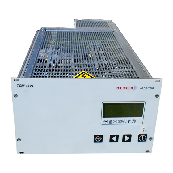
Summary of Contents for Pfeiffer Vacuum TCM 1601
- Page 1 PFEIFFER VACUUM Betriebsanleitung ........ Seite 2 Operating Instructions ....... Page 27 Magnetlagerelektronik Magnetic Bearing Controller (€ • •...
- Page 2 1. Wichtig fiir lhre Sicherheit ....3 6. Betrieb ............ 6.1. Einschalten des Geriites ..........16 2. Kennenlernen der TCM 1601 ....4 Selbsttest................16 2.1. Zu lhrer Orientierung ............4 6.2. Pumpstand einschalten ..........16 2.2. Produktbeschreibung ............4 Normalbetrieb der Turbopumpe ........
-
Page 3: Table Of Contents
......LC Display ................36 10. Technical Data ........49 4.3. Abbreviated Overview Operating ........37 10.1. Data List, Magnetic Bearing Electronic TCM 1601 ..49 4.4. Operating Examples ............37 10.2. Dimensions Diagram ............49 Illuminated Displays ............38 11. -
Page 8: Mains Power Connection
Voltages of up to 50 V eff· can be present on the DANGER accordance with connections diagram section 3.2. open connection of a running down pump. • Use the mains cable from the TCM 1601 for the TCS 180 mains connection. There is a danger of an electric shock by �... -
Page 9: Connecting The Remote Control Unit
Pin Arrangement X2 0 3.9. Connecting The Remote Control Unit The TCM 1601 or the complete pumping station can be remote Descri tion Function controlled via plug Xl 6. Before connecting the remote X20.1 Closer control, the remote mode should be selected {please refer to X20.2... -
Page 10: Connecting The Pressure Gauges
1 ..8 ped with a 9 pole D-SUB plug connector, an RJ45 Western Plug and a connecting cable. Arrangement • Connect the level converter to X17/TCM 1601 by an equiva not connected lent cable. +15V output (,,;150mA loading capacity) not connected 3.14. -
Page 11: Operating And Display Elements
4.1. Operating Elements The four push-buttons on the front panel have the following functions: Push-Button Application/Example Explanation (malfunction acknowledgement) Reset ...- ,� acknowledges malfunctions (red LED illuminates) � -<&309: Act rotspd Scroll Parameters Backwards -<&310: TMP I-Mot scrolls a parameter backwards (with arrow "->") ->... -
Page 12: Display Elements
4.2. Display Elements Symbol Definitions LC Display Display Explanation Symbol Meaning 721: Vent time Pump ---> 120 Line2 accelerates d ata not changed - ----FI- Line3 �r'\7 �, �B Pre-selection - Line 4 e� - 11: · · • · , , , , . . housing-/ Pre-selection heating ON TMS-... -
Page 13: Abbreviated Overview Operating
4.3. Abbreviated Overview, Operating Operating Examples Switching on the magnetic bearing controller • Switch on the unit on the rear side with switch Sl. Switching on the pumping station • Select «794: Param. Set» and set to «1 » • Check set values [P:7xx] and setting commands [P:Oxx] Casing heating ON/OFF .�. -
Page 14: Illuminated Displays
Set values numerical modifying of a value The total of the available parameters represents a parameter user the TCM 1601 provides three parameter sets which dif set. fer from each other in the number of parameters and their sorting. The respective parameter set can be selected via the To adapt this parameter to the individual requirements of the parameter «794: Param. -
Page 15: Parameter Overview, Numerical
• 5.2. Parameter Overview, numerical Setting Commands (readable and writable) Name, Description fact. set. RS 485 Data tvo Display Pre-selection, heatina. 0=OFF; 1=ON OFF"l Heatina l'ii'I l'ii'I Standby Standby 0=off; 1=on OFF"' l'ii'I Run-up time monitoring, 0=OFF; 1=ON RUTime ctr 008* Kevboard interlock 009*... -
Page 16: Parameter Overview, Operational
5.3. Parameter overview, operation oriented Disela'.I' Name, Descrietion fact. set. S ect. R S 485 Run up time and switch point • 004 I RUTime ctr Run-up time monitorinQ ON/OFF • TMP RUTime Maximum run-up time in mins 6.2.,6.4. • Switch Pnt Switchpoint 6.4.,6.11. -
Page 18: Air Cooling On/Off
In addition to the parameters referred to above, further infor Gas mode characteristic mation/functions which support operations with the TMS are available. Request TMS temperature • Select «331: TMS ActTmp» • Read the current temperatur. TMS temperatur attained? D-C = Gas mode «0» •... -
Page 19: Rotation Speed Setting Via Inlet Pwm
• Select «794: Param set», set to «1 ». Section 3.11.) the pressure in the vacuum chamber is display • Select «701: Switch pnt» «50 ..90%». ed on the TCM 1601. • Select «703: HVVthrshld» • Adjust «1-10- 1 .. s-10 [mbar]». -
Page 21: Remote Control
Remote Control Priority "ON" Venting release Where certain application situations are involved, for exam • Select «012: Vent enab», set to «ON». ple SPC control, the remote control functions can be assigned prioritized switching. Three venting modes can be selected in the extended parameter set With f=0Hz: •... -
Page 22: Serial Interface Rs 485 Operations
6.17. Emergency Current Operations With Battery Box TBB 001 The group adress of the TCM 1601 is 988. All units connected to the bus must have differing serial interface adresses The battery box TBB 001, connected to X29, takes over the [P:797]. -
Page 23: Error Messages And Warnings
Meaning �rises when when resettable Troubleshooting «Error Exxx» E001 Excess rotation speed TMP Pump at rest PFEIFFER service E006 Start-up time error anytime Adjust run up time correctly, open fore vacuuum valve Remove the leak, reduce fore vacuum pressure E014 In the self test recognized heating rate Change the heating or cooling configuration is modified bv pullina the Plua or malfunction... -
Page 24: What To Do In The Case Of Breakdowns
Check The Fuses During operations, the last ten errors and warnings are saved In case of defects: in parameter [P:303] «Error Code». • Remove Fl and F2 using a screwdriver and check fuses. Replace if defective. The fuse values are printed on the If an error cannot be remedied: reverse side of the fuse. -
Page 26: Connections Diagram
VJN12-10V I • G•=od > Vs :+15-31!11/ � � FW-f-OUT C") -· �- Pressure gauge � LCNO TCM 1601 � TPR250 / PUR250 >!27 ,------------, _ UV __ _ TCS 180 Ground s1gnsl � ==t=± � -°" SEMDTE +1!5Vtt iD=d �... -
Page 27: Accessories
Description Size Number Operating Order Quantity/ Instructions Comments Pumping S tation Control Unit TCS 180 100 - 2 40 V; 50/60 Hz PM C0l 655 PM 800 384 BN Mains cable - S chuko P4564309 - US-version 115V P4564309 ZE - US-version 2 08V P4564309 ZF... - Page 29 Korea Assistencia Tecnica e Representa,ao S / C Ltda. 690 Sukhumvit Road Rua Bernadina de Compos, 551 Pfeiffer Vacuum Korea Ltd., 3F Haein Building 453, Klongton, Klongtoey CEP 04620-002 Sao Paulo, SP - Brasil Dokok-Dong, Kang Nam-Ku, Seoul, 135-270 Bangkok 10110...
Need help?
Do you have a question about the TCM 1601 and is the answer not in the manual?
Questions and answers