
Related Manuals for Pfeiffer Vacuum IMG 400


Summary of Contents for Pfeiffer Vacuum IMG 400
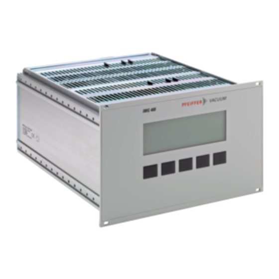
- Page 1 OPERATING INSTRUCTIONS Translation of the original instructions IMG 400 Ionization G auge C ontroller...
-
Page 2: Table Of Contents
5.1 Switching Function Parameters (Setpoint) 5.1.1 Fundamental Terms 5.1.2 Configuring Switching Functions 5.1.3 Setting Range 5.2 General Parameters (General) 5.2.1 General Settings (Setup) 5.2.2 Interface Parameters (RS232) 5.2.3 Device Control (Control) 5.2.4 Recorder Outputs (Recorder) BG 5520 BEN / A (2018-10) IMG 400... - Page 3 5.2.5 Display, Bar Graph (Disp.Bar) 5.2.6 Threshold Values (Threshold) 5.2.7 Behavior of the IMG 400 in Case of an Error (Error) 5.3 Gauge Parameters (Sensor) 5.3.1 Measuring Channel (Channel) 5.3.2 Measurement Filter (Filter) 5.3.3 Automatic Offset (Auto_OFS) 5.3.4 Sensitivity Adjustment (Cal_Full) 5.3.5 Filament Power Control (Fil.Pow)
-
Page 4: Introduction
The IMG 400 can handle four measuring systems simultaneously. An optional interface may be used for complete remote control of the device. In the following, the Ionization Gauge Controller IMG 400 will be referred to as «IMG 400». Designation 1.3 Scope of Delivery... -
Page 5: Safety
1.4 Safety Personnel qualifications All work described in this document may only be carried out by persons who have suitable technical training and the necessary experience or who have been instruc- ted by the end user of the product. Illustration of residual dangers This Operating Instructions illustrates hazard alerts concerning residual dangers as follows: Danger... -
Page 6: Liability And Warranty
Caution Improper use. Improper use can damage the IMG 400. Use the IMG 400 only as intended by the manufacturer (→ Intended Use, 4). Caution Improper installation and operation data. Improper installation and operation data may damage the IMG 400. -
Page 7: Technical Data
2 Technical Data Mechanical data Weight approx. 3 kg desktop device, control panel mounted, rack mounted Dimensions [mm] Environment Temperature Storage -20 … +60°C Operation +5 … +40°C Relative humidity max. 80% (up to 30 °C), decreasing to max. 50% (above 40 °C) indoors only, altitude max. - Page 8 CMR 361 … CMR 365 F.S. [hPa] Pressure range [hPa] 1×10 … 1×10 1×10 … 1 1×10 … 1×10 1×10 … 1×10 1000 1×10 … 1×10 5×10 … 1×10 TPR 280, TPR 281 BG 5520 BEN / A (2018-10) IMG 400...
- Page 9 Accuracy of measurement Current Channels 1 and 2 Relative to current reading ±2% Absolute ±5 fA Voltage Channels 3 and 4 Relative to voltage reading ±1% Absolute ±2 mV Measuring speed The measuring speed that can be achieved with IMR gauges depend on the ion current to be measured and the selected resolution (details →...
- Page 10 2400, 4800, 9600, 19200, 38400, 57600, 115200 Data 7-Bit, 8-Bit, 9-Bit Parity odd, even, none Stop bits 1, 2 Interface board (option) Interface board with Profibus DP interface Breaking capacity for voltage 30 VDC / 50 VAC BG 5520 BEN / A (2018-10) IMG 400...
-
Page 11: Installation
3.2 Mechanical Installation The IMG 400 can be used as follows: As a desk-top device, mounted in a control panel, or mounted in a 19" rack. In each of these cases you must pay attention to... -
Page 12: Installation In A Control Panel
If required, fold out the two front feet. Turn the IMG 400 back to normal orientation and place it on the required location. 3.2.2 Installation in a Control In order to mount the device in a control panel, the following cutout is required... -
Page 13: Rack Installation
Fasten the rack chassis adapter in the rack. Insert the IMG 400 into the rack chassis adapter. Fasten the IMG 400 with the supplied collar screws and plastic sleeves to the rack chassis adapter. BG 5520 BEN / A (2018-10) -
Page 14: Connecting
Do not turn or loosen these screws. The configuration of the available connections is described in the following sections. BG 5520 BEN / A (2018-10) IMG 400... -
Page 15: Mains Connection
3.3.3 Ground Protective conductor The ground screws (→ pos. I, 14) can be used to connect the IMG 400 with the protective ground of the pumping station. If required: Connect the protective ground of the pumping station with the ground screw. -
Page 16: Ch1 And Ch2
(→ pos. N and O, 14). Caution Improper gauge. Gauges which are not designed for use with the IMG 400 may damage the device. Operate the IMG 400 with proper gauges only (→ 7). BG 5520 BEN / A... -
Page 17: Relay
The switching functions and the error monitoring system influence the states of several relays inside of the IMG 400. The RELAY connection (→ pos. A, 14) allows to utilize the relay contacts for switching purposes. The relay contacts are potential-free (floating). -
Page 18: Control
An interface board in the extension slot (→ pos. M, 14) can be used to extend the device with 5 more relays and one more interface. Usable interface board: Interface board with Profibus DP interface BG 5520 BEN / A (2018-10) IMG 400... -
Page 19: Operation
4 Operation 4.1 Front Panel Channel Status display (black letters) Gauge type Trigger relay status Status row Pressure unit Menu name Bar graph measurement display Digital measurement display Control buttons Status display (white letters) 4.1.1 Display Status row The most important system states are always displayed in the top row (pos. C) no matter which menu is selected. - Page 20 Device is controlled via RS232 of the optional interface board (→ "Device Control (Control)", 39) RS232 Device is controlled via RS232 and the IMG 400 protocol (→ "Device Control (Control)", 39) Remote Device is controlled via discrete remote control inputs (→ "Device Control (Control)", ...
-
Page 21: Control Buttons
Overtemp signal of the power supply is active, measurement cannot be performed WaitCon IMG 400 Mode, gauge control function activated, the displayed channel is waiting for release by the controlling system CodErr The identification resistance of a previous connected gauge cannot... - Page 22 Related configuration parameters → "Parameters", 36. If no button is pressed in one of the submenus within the «Timeout» period, the device returns to the measurement screen. Selected parameters (if any) will remain unchanged. BG 5520 BEN / A (2018-10) IMG 400...
-
Page 23: Switching On And Off
Wait for at least 10 seconds before you switch the IMG 400 on again. If the IMG 400 has been installed in a control panel or a rack, it can also be switched on and off via the central power distributor. -
Page 24: Measurement Mode
(→ "Test Mode", 59). 4.4 Measurement Mode 4.4.1 Selecting Measurement The IMG 400 automatically selects the measurement mode after it has been Mode switched on From any other mode, you can return to the measurement mode by pressing the Return button once or several times. -
Page 25: Switching Emission On
4.4.4 Switching Emission On Caution Excessive gas pressure. Excessive gas pressure at the measurement position can damage the gauge. Before switching the emission on, check to make sure that the pressure at the measurement position does not exceed the following values: •... -
Page 26: Switching Emission Off
Bayard-Alpert gauge • p < 1×10 hPa for the Extractor gauge You can switch on the degas function as follows: Select the required channel (→ "Selecting a Channel", 24). BG 5520 BEN / A (2018-10) IMG 400... -
Page 27: Switching Degas Function Off
Press the Cmd button. Press the Deg.On button. • The degas function for the gauge of the selected channel is switched on • The «Degas» signal in the status row flashes • During degassing, there is no pressure measurement. The last valid measured value is displayed. -
Page 28: Deactivating Offset
Press the Cmd button (→ fig. 27). Press the Ofs.Res button. • The offset value is reset to 0 • The «OFS» signal in the status row is dark BG 5520 BEN / A (2018-10) IMG 400... -
Page 29: Detail View Mode
4.5 Detail View Mode 4.5.1 Selecting Detail View Press the Detail button Mode The device changes to the detail view mode. Several groups are being offered for selection on the display (→ "Detail Groups", 29). You can exit the detail view mode by pressing the Return button. 4.5.2 Detail Groups For clarity, the values displayed in the detail view mode are arranged in groups. - Page 30 (→ " Behavior of the IMG 400 in Case of an Error (Error), 43). The device distinguishes between the following two emergency off events: •...
-
Page 31: Parameter Mode
The parameter mode gives you access to various parameters. You can check the parameter settings or modify them using the arrow buttons. This allows you to configure the IMG 400. The following table shows all available parameter groups and parameters. - Page 32 (→ "Switching Function Parameters (Setpoint)", 36). General parameters (General) These parameters are used for general configuration of the device. The parame- ters affect all channels (→ "General Parameters (General), 37). BG 5520 BEN / A (2018-10) IMG 400...
-
Page 33: Basic Operation
Press the Enter button: • The cursor appears at the selected parameter value. • The IMG 400 is now in the edit mode. The Return button is replaced by the ESC button. BG 5520 BEN / A (2018-10) IMG400.opi... -
Page 34: Displaying And Handling System Errors
System Errors 4.8.1 Displaying System Errors The IMG 400 can store up to 20 different errors. Any error that occurs is stored in the error list, provided that it has not been stored in the list already. New errors are no longer added to the list if the list is full. - Page 35 Select the Error detail group and then press the Enter button: • The labeling of the Enter button changes to «Reset». Use the arrow buttons to select the error message you want to delete. Press the Reset button: •...
-
Page 36: Parameters
5.1.1 Fundamental Terms Switching functions The IMG 400 is equipped with four relays which switch in dependence of the mea- sured pressure. These relays will be referred to as «relay 1» and «relay 2». The number of relays can be increased to 7 by upgrading the device with an interface board. -
Page 37: Configuring Switching Functions
Pressure Normally open contact (make contact) Time Common contact Normally closed contact (break contact) The region between the threshold values generates a hysteresis (lag) between activating and deactivating of the relay. The hysteresis prevents the switching function from rapidly switching on and off when the pressure is close to one of the threshold values. - Page 38 The brightness of the background illumination can be adjusted in the range Illumination (Light) 0 … 100% in 1% steps. Display Contrast (Contrast) The display contrast can be adjusted in the range 30 … 50% in 1% steps. BG 5520 BEN / A (2018-10) IMG 400...
-
Page 39: Interface Parameters (Rs232)
A maximum of two stop bits can be set. 5.2.3 Device Control (Control) The Control parameter determines how the IMG 400 is operated and controlled. This parameter is only available in the standard operating mode. BG 5520 BEN / A (2018-10) IMG400.opi... -
Page 40: Recorder Outputs (Recorder)
The buttons (except for emergency-off) can be locked via the RS232 interface. 5.2.4 Recorder Outputs The IMG 400 is equipped with two recorder outputs which can be configured. The (Recorder) recorder output voltage is kept at a constant level during the following actions. - Page 41 Display Output Full The entire pressure range of the selected gauge is transformed to an output voltage of 0 … 10 V. Source: Chan 1-4 P_Low: Lower range limit of the connected gauge (not modifiable) P_High: Upper range limit of the connected gauge (not modifiable) Expo The exponent of the reading of the related gauge is output.
-
Page 42: Display, Bar Graph (Disp.bar)
MIN_Pressure_User and MAX_Pressure_User are the range limits set by the user and are also displayed as P_Low and P_High in the IMG 400 display. If the characteristic curve is set to (Scale) = Log, the voltages for the recorder out-... -
Page 43: Threshold Values (Threshold)
5.2.7 Behavior of the IMG 400 The behavior of the IMG 400 in special or error situations can be configured by the in Case of an Error user. - Page 44 It will be restored after the faulty gauge has been re- placed, the device reset (mains switch turned off and on), and two working gauges are found at the IMG 400. Error Signal Relays (FailRel1, The two error signal relays can be assigned to the four measurement channels as...
- Page 45 Emi.Tol. The following gauge parameters are monitored constantly during operation. A re- ference to the related warning or error message is shown in parentheses. • Anode voltage (U_Anode) • Cathode voltage (U_Cathode) • Reflector voltage (U_Reflector) • Emission current (I_Emis) •...
-
Page 46: Gauge Parameters (Sensor)
The filter can be set to one of the following values: None (n = 1) The filter is deactivated. Fast (n = 5) The IMG 400 responds quickly to signal changes. This makes it rather sensitive to signal noise. BG 5520 BEN / A (2018-10) -
Page 47: Automatic Offset (Auto_Ofs)
This is the default setting. It offers a good compromise between the response time and the sensitivity to noise. Slow (n = 50) The IMG 400 responds slowly to signal changes. This makes it less sensitive to signal noise. This setting is recommended for precise comparison measurements. 5.3.3 Automatic Offset... -
Page 48: Filament Power Control (Fil.pow)
The status row displays the «COR» signal for the respective channel. User Automatic gas type correction according to correction factors input by the user (→ "User- Defined Correction Factors (Correct > Clear- All, Index, Factor, Press), 49). BG 5520 BEN / A (2018-10) IMG 400... -
Page 49: Additional Correction Factor (Correct > Cor.gain)
5.3.10 User Defined Correction The IMG 400 allows you to define your own table of correction factors for each Factors (Correct > gauge. These correction factors can be used for gas type correction as well as for correction of other measuring errors. - Page 50 Cor.Mode parameter is set to «None» (→ "Automatic Gas Type Correction (Correct > Cor.Mode)", 48). Any attempt to set the Cor.Mode parameter to «User» also causes an error mes- sage. BG 5520 BEN / A (2018-10) IMG 400...
-
Page 51: Current Amplifier Parameters (Ioniamp)
The smallest «full range» selection is 100 fA. In this range, the IV540 is very Parameters (IoniAmp) sensitive and it will therefore react on external interference. The device firmware in the IMG 400 always selects the best measuring range auto- matically. Previously, for pressures below 1E-11 hPa, this was the 100 fA range exclusively. -
Page 52: Activation Source (Source)
If the pressure falls below the activation value P_On, the respective gauge is tion Values (P_On, P_Off) switched on. If the pressure rises above the deactivation value P_Off, the res- pective gauge is switched off. BG 5520 BEN / A (2018-10) IMG 400... -
Page 53: User Parameters (Usermode)
«Manual» automatically (→"Gauge Activation Mode (Mode)", 51). 5.6 User Parameters The IMG 400 is able to detect the connected gauges and interface boards and the current mains frequency automatically. It will use the optimum settings for each (UserMode) gauge. -
Page 54: Configuring The Device (Amplifier)
1. That way the system is still operable. MainFreq Mains frequency. Interf. Type of interface board mounted in the extension slot. A modified parameter will be adjusted automatically only after the value «Auto» has been assigned to it. BG 5520 BEN / A (2018-10) IMG 400... -
Page 55: Graphic Parameters (Detail Graphic)
5.7 Graphic Parameters (Detail Graphic) 5.7.1 Parameters and The Detail > Graphic menu is used to adjust parameters for the trend graphic and Functions to start recording a graphic. Value Display/ Selection Significance 1−BAG, 1−EXT Channel Selection of a channel whose trend graphic 2−BAG, 2−EXT is to be specified or displayed. - Page 56 The horizontal axis uses a linear scale and represents the time. The entire range is specified by the «Time» parameter. This parameter is displayed in the upper right corner of the display (example: t = 00.50 h). BG 5520 BEN / A (2018-10) IMG 400...
-
Page 57: Maintenance, Service
The operating hour counter is reset to zero. 6.2 Program Transfer Mode If your IMG 400 requires an updated firmware version, e.g. for using a new gauge type, please contact your local Pfeiffer Vacuum service center. The user parameter settings are no longer available after the firmware update. -
Page 58: Restarting
They are checked by a mathematical pro- With Default Parameters cedure (CRC-Check). If the stored data are damaged in any way IMG 400 starts up properly. The effected parameter values are set to the default settings. Additionally the following error message is generated. -
Page 59: Test Mode
6.4 Test Mode Caution Test mode. All monitoring functions of the IMG 400 software are switched off in the test mode. Improper operation can cause damage to the device. Only authorized personnel are allowed to select and to use the test mode. - Page 60 Use the arrow buttons to select the required subgroup. Then press the Enter button. • The IMG 400 is now in the test mode. The «Test» field in the status row is flashing. BG 5520 BEN / A (2018-10)
-
Page 61: Test Parameters And Functions
6.4.2 Test Parameters and The test parameters and functions can be found in the subgroups of the Test Mode Functions parameter group. The following table lists all available subgroups and the related parameters and functions. 1. Subgroup 2. Subgroup Function CPU/Disp Commands Default... -
Page 62: Cpu / Display
3 and 4 • Disable: The IMG 400 continues measuring even after a «fatal error» has occurred, i.e. the emission and the sup- ply voltages for the channels 3 and 4 remain switched on. -
Page 63: Current Measuring Amplifier (Amplifier)
Tests The following hardware tests can be started in this submenu: Display Significance RAM * Test the main memory. CRC-ROM * Check the check sum of the program memory. EEPROM * Check the check sums of all EEPROMs. Display * At first, «X»’s are written with standard font size on the entire display. - Page 64 Display the currently selected measuring range Resolut. Display the measuring resolution Measure Display the current measuring value Mod_Freq Display the modulator frequency CycleT. Display the current measuring time Capacity Display the set integrator capacity BG 5520 BEN / A (2018-10) IMG 400...
-
Page 65: Power Supply
Intern The following data are displayed in this menu: Display Significance Temp. Display the temperature of the current amplifier assembly in °C Display range: 0.100 °C Resolution: 0.1 °C Offset Display the offset value Display range: 0 … 4095 New_DA Display the new DA value Measure Display the current measuring value... -
Page 66: Inputs / Outputs
0000010: Channel 1 ready • 0000100: Degas • 0001000: Emission • 0010000: Channel • 0100000: Trigger 2 • 1000000: Trigger 1 The test mode for this value is switched off if «auto» is selected. BG 5520 BEN / A (2018-10) IMG 400... -
Page 67: If 400X
RS232 This menu displays the most recently received and transmitted string of the RS232 interface. Display Significance Receive Most recently received string Transmit Most recently transmitted string Display Significance 6.4.7 IF 400x Relays Display and control of the five relays. The states are dis- played in binary: •... -
Page 68: Storage And Disposal
Please keep the original packaging. The packaging is required for storing the IMG 400 and for shipping it to Pfeiffer Vacuum service center. 7.2 Storage The IMG 400 may only be stored in a dry room. The following requirements must be met: Ambient temperature: -20 …... -
Page 69: Appendix
Display Mode ----- → "Threshold Values, Spt.Low Trigger Values", 73 Spt.High Trigger Enable [Param] > [General] Display Default User Device IMG 400 Control RS232 [Param] > [General] > [Setup] Display Default User Unit mbar Torr Set.Lock Light Contrast Men.Time... - Page 70 Display Default User [Param] > [General] > [Sensor] Channel Filter Normal Auto_OFS ----- Cal_Full IMR 430: 6.6 hPa IMR 420: 16.6 hPa CMR: 1000 Torr Fil.Pow. 7.0 W Emis.Cur Auto X_Ray 0.00E+00 BG 5520 BEN / A (2018-10) IMG 400...
- Page 71 Display Default User [Param] > [General] > [Correct] Channel Cor.Mode None Cor.Gain 1.00 ClearAll Index Factor 1.000 Press Upper range limit of the gauge [Param] > [Ioni Amp] Display Default User Channel 1-BAG Sens. Normal [Param] > [Control] Display Default User General Channel...
- Page 72 Emis.Cur Auto Anode Auto Emission Auto I_Shunt ----- F_Inhib. Auto PID_Ctrl. Auto Channel Auto Display Default User [Param] > [TestMode] > [I/O] > [Gauge] Meas_3 Meas_4 Ident_3 Ident_4 Supl.CH3 Auto Supl.CH4 Auto BG 5520 BEN / A (2018-10) IMG 400...
-
Page 73: B: Setting Ranges
Display Default User [Param] > [TestMode] > [I/O] > [Control] Rec_1 Auto Rec_2 Auto Analog_1 Analog_2 Digital Relays Auto [Param] > [TestMode] > Display Default User [IF400x] Relays Auto Receive Transmit Ident. Setting Ranges Threshold Values, Trigger Values Gauge Spt.Low min. Spt.Low max. - Page 74 2.133s 8192 7.813ms 31.250ms 125.000ms 250.000ms 500.000ms 2.000s 50,60 10240 6.250ms 25.000ms 100.000ms 200.000ms 400.000ms 1.600s 50,60 12288 5.208ms 20.833ms 83.333ms 166.667ms 333.333ms 1.333s 12800 5.000ms 20.000ms 80.000ms 160.000ms 320.000ms 1.280s (continued) BG 5520 BEN / A (2018-10) IMG 400...
- Page 75 (Table "Measuring Speed" concluded) Mod. Freq. Resolution (s/ms/us) Rejection [Hz] 6 Bit 8 Bit 10 Bit 11 Bit 12 Bit 14 Bit [Hz] 15360 4.167ms 16.667ms 66.667ms 133.333ms 266.667ms 1.067s 17067 3.750ms 15.000ms 59.999ms 119.998ms 239.995ms 959.981ms 20480 3.125ms 12.500ms 50.000ms 100.000ms 200.000ms...
- Page 76 BG 5520 BEN / A (2018-10) IMG 400...
-
Page 77: C: Menu Structure
Menu Structure Detail-Selection Detail Selection Error > > > Setpoint > > > Graphic > > > Gauge > > > Pressure > > > Info > > > Emi.On Enter Return Detail Error No Errors Pending ... - Page 78 FW-Vers.: – – – – – HW-Vers: Emi.On Return Info VP-Board Artic.-No: Seria.No: Cal-Date: FW-Vers. – – – – – HW-Vers: Emi.On Return Info IV-Board Artic.-No: Seria.No: Cal-Date: FW-Vers.: HW-Vers: Emi.On Return BG 5520 BEN / A (2018-10) IMG 400...
- Page 79 Parameter-Selection ParameterSelection Setpoint > > > Control > > > General > > > UserMode > > > Sensor > > > TestMode > > > Ioni Amp Emi.On Enter Return SetpointParameter Setpoint: Relay1 Spt.Low: 2.00E-11 Channel: 1-BAG Spt.High: 8.00E-03 Display:...
- Page 80 Return Test Mode CPU/Disp > > > > > > Amplif. > > > IF40x > > > Page Test-Mode Power > > > Internal > > > Emi.On Return BG 5520 BEN / A (2018-10) IMG 400...
- Page 81 Test-Mode Test Mode CPU/Disp > > > > > > Amplif. > > > IF400x > > > Power > > > Internal > > > Emi.On Enter Return Test CPU/Disp Test Test CPU Commands Test Commands: > > > Default: Ready Config.:...
- Page 82 Test I/O RS232 Test Receive: Transmit: Emi.On Return Test IF400x Test Relays: Auto Ident: 2.480V Receive: Transmit: Emi.On Enter Return Test Internals Test OS_Overr: CRC_ROM: BE9D Rec.Unex: Max.Resp: Emi.On Return BG 5520 BEN / A (2018-10) IMG 400...
-
Page 83: D: Error Messages
1, 18 6.4.6 the RS232 input 6.4.6 Incompatible Profibus SW- Communication trouble bet- 106, 6.4.6/6.4.7 Version ween IMG 400 and Profibus 107, 6.4.6/6.4.7 interface IF 540 P Set Cor_Mode To Gas correction is reset because 121, 6.4.5/6.4.6 NONE.Sensor Changed the gauge for the active chan- 122, 6.4.5/6.4.6... - Page 84 (Table "Error Messages" continued) Error message Error description Channel 4 No Coding IMG 400 does not recognize 1, 13 130, 6.4.5 the gauge connected to chan- 6.4.5 nel 4 properly 6.4.5 Ioni Amp. Offset Failure Offset adjustment for the mea- 14, 15 —...
- Page 85 (Table "Error Messages" continued) Error message Error description VP-Board Power Supply +24 V supply for external relays 1, 16 6.4.5/6.4.6 +24VKL Error at the «Relay» plug is missing 6.4.5/6.4.6 or shows an unacceptable de- 6.4.5/6.4.6 viation from the setpoint VP-Board Power Supply +5 V supply for the RS232 1, 16 6.4.5/6.4.6...
- Page 86 EEPROM on the MC board Ioni Amp. EEPROM Communication error between 1, 4 — 6.4.3 Operation Timeout the processor and the EEPROM of the measuring amplifier on the IV board (continued) BG 5520 BEN / A (2018-10) IMG 400...
- Page 87 (Table "Error Messages" continued) Error message Error description IQ Board EEPROM Communication error between 1, 4 — 6.4.3 Operation Timeout the processor and the EEPROM on the IQ board VP Board EEPROM Communication error between 1, 4 — 6.4.3 Operation Timeout the processor and the EEPROM on the VP board IF Board EEPROM...
- Page 88 6.4.5 MC-Board Power Supply –15 V supply on the MC board 23, 16 6.4.5 −15V Error is missing or shows an unac- 6.4.5 ceptable deviation from the setpoint (continued) BG 5520 BEN / A (2018-10) IMG 400...
- Page 89 (Table "Error Messages" continued) Error message Error description MC-Board Power Supply +5 V supply on the MC board is 20, 21, 6.4.5 +5V Error missing or shows an unac- 6.4.5 ceptable deviation from the setpoint MC-Board Power Supply +15 V supply on the MC board 23, 16 6.4.5 +15V Error...
-
Page 90: E: Legend For The Error Table
Depending on the configuration of the device (→ 5.2.7, 43), the 101 … 250 cause of the error and the previous history, further error messages may be triggered. The most frequent follow-up errors are listed in this column. BG 5520 BEN / A (2018-10) IMG 400... - Page 91 Disturbances in the RS232 cable, caused by electric or magnetic interference or by faulty/improper wiring RS232 configuration of the IMG 400 is not compatible with the one of the connected device Wrong firmware installed in the IF 400 P board (→ [5]).
- Page 92 Enter the device parameters again Check the RS232 parameter settings of the IMG 400 and the connected device (PC, control, etc.). Correct the settings if necessary. Check the interface cable and plug-in connections. Replace the parts if necessary.
-
Page 93: F: Literature
Bayard-Alpert and Extractor Gauges IMR 420, IMR 430 BG 5034 BEN Pfeiffer Vacuum GmbH, D–35614 Asslar, Deutschland [4] www.pfeiffer-vacuum.com Communication Protocol RS232C Serial Interface for IMG 400 BG 5525 BEN Pfeiffer Vacuum GmbH, D–35614 Asslar, Deutschland [5] www.pfeiffer-vacuum.com Communication Protocol... -
Page 94: E U Dec Laration Of C Onformity
E U Dec laration of C onformity We, Pfeiffer Vacuum, hereby declare that the equipment mentioned below com- plies with the provisions of the Directive relating to electrical equipment designed for use within certain voltage limits 2014/35/EU, the Directive relating to electro- magnetic compatibility 2014/30/EU and the Directive on the restriction of the use of certain hazardous substances in electrical and electronic equipment 2011/65/EU. - Page 95 Notes BG 5520 BEN / A (2018-10) IMG400.opi...
- Page 96 VACUUM S OLUTIONS FR OM A S INGLE S OUR CE Pfeiffer Vacuum stands for innovative and custom vacuum solutions worldwide, technological perfection, competent advice and reliable service. COMPLE TE R ANGE OF PR ODUCTS From a single component to complex systems: We are the only supplier of vacuum technology that provides a complete product portfolio.
Need help?
Do you have a question about the IMG 400 and is the answer not in the manual?
Questions and answers