Table of Contents
Advertisement
Quick Links
Advertisement
Table of Contents

Related Manuals for Pfeiffer Vacuum TC 400 PB


Summary of Contents for Pfeiffer Vacuum TC 400 PB
- Page 1 TC 400 PB Electronic Drive Unit Operating Instructions...
-
Page 2: Table Of Contents
6.4 Expanded diagnostics data ........16 The Pfeiffer Vacuum parameter set ....... . 17 General . -
Page 3: About This Manual
1 About this manual 1.1 Validity This operating manual is for customers of Pfeiffer Vacuum. It describes the func- tioning of the designated product and provides the most important information for safe use of the unit. The description follows applicable EU guidelines. All informa- tion provided in this operating manual refer to the current state of the product's de- velopment. -
Page 4: Safety
• Power supply: The turbopump power supply must apply to the requirements of double insulation between mains input voltage and operating voltage according to the regulations of IEC 61010 and IEC 60950. Therefore Pfeiffer Vacuum recom- mends to use exclusively original-power packs and -accessories. Only in this case Pfeiffer Vacuum is able to guarantee the compliance of the European and North American guidelines. -
Page 5: Proper Use
Service. 2.4 Functional safety The drive unit (electronic drive unit) TC 400 PB performs the safety function "Safe Limited Speed" according to EN 61800-5-2. In case of excess rotation speed the commutation of the pump motor is switched off and the drive transferred into the safe condition. -
Page 6: Product Description
Product description 3 Product description 3.1 Product identification Product features The electronic drive unit TC 400 PB is an integrated component of the turbopump. It's purpose is to drive, monitor and control the entire pump. Characteristics TC 400 PB Connection voltage TC 24 V DC ±... -
Page 7: General Connection Description
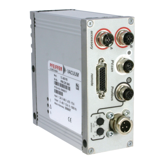
Casing plug with bayonet locking for the voltage supply between Pfeiffer Vac- uum mains packs and the electronic drive unit TC. Accessory M12 socket with screw coupling for the connection of Pfeiffer Vacuum acces- sories. The use of a Y-connector enables double assignment of one connec- tion. -
Page 8: Connections Diagram
Relay 2 + U B (+24 / +48 VDC ± 5 %) Relay 2 Relay 2 Relay 3 Relay 3 DO Remote priority active RS485 D+ RS485 D- GND* Fig. 2: Connections diagram and assignment of the TC 400 PB... -
Page 9: Connection "Remote
Remote control options are provided via the 26-pole D-Sub connector with the des- ignation ”remote“ on the electronic drive unit. Remove the remote plug from the TC 400 PB and connect a remote control unit. Pin assignment of the connector according to table. - Page 10 The digital inputs at connection "remote" are used to connect various functions of the electronic drive unit. Functions are assigned to the inputs DI1 - DI2 ex factory. These are configurable by the Pfeiffer Vacuum parameter set via Profibus or the in- terface RS485.
- Page 11 Connection "remote" AI Rotation speed setting mode / Pin 7 and Pin 11 The analog input at the TC 400 PB defines the set rotation speed of the turbopump. f(%) An input signal of 2 - 10 V between AI+ (Pin 7) and AI- (Pin 11) corresponds to a ro- tation speed within the range of 20 - 100% of the nominal rotation speed.
- Page 12 Connection "remote" RS485 One Pfeiffer Vacuum display and control panel (DCU or HPU) or an external PC can be connected respectively to the electronic drive unit via Pin 24 and Pin 25 of the connection "remote" on the electronic drive unit.
-
Page 13: Connection "Profibus
Control/status bits • Data format is always "high word/byte first" (Motorola) • All Pfeiffer Vacuum parameters of data type 0, 1, 2 and 7 can be used for the pa- rameter channel (PPO1) and the parameterization data. – Avoid conflicts with existing functions! •... - Page 14 Connection "Profibus" • Output data describe the data communication from the master (e.g. PLC) to the electronic drive unit. • Input data describe the data communication from the electronic drive unit to the master (e.g. PLC). PPO1 Byte Output data (12 bytes) Input data (12 bytes) Parameter channel with request Parameter channel with response...
- Page 15 Connection "Profibus" Output data Input data Rotation speed setting mode Automatic trip switch (switching back on only by pumping station off and back on) Errors Operation (no error, pumping station and motor pumps are on, no automatic trip switch) Pumping station Standby (no error, no automatic trip switch, enable process data) PPO3...
-
Page 16: Expanded Diagnostics Data
Connection "Profibus" 6.4 Expanded diagnostics data Byte Designation Description Standard diagnostics Profibus Defined by Profibus specification Length of the external diagnostics data 8-36 Reserved 37-38 Current error code 0: No error 1-999: Device error* 1001-1999: Device warning 1-999* 2000: Unrecognised module 3xxx: Parameterization data incorrect in ac- cordance with error number in the parame- ter channel**... -
Page 17: The Pfeiffer Vacuum Parameter Set
RS485 with the Pfeiffer Vacuum protocol. NOTE Profibus and Pfeiffer Vacuum parameters All Pfeiffer Vacuum parameters of data type 0, 1, 2 and 7 can be used for the parameter channel (PPO1) and the parameterization data. Avoid conflicts with existing functions in the modules. - Page 18 The Pfeiffer Vacuum parameter set Only for Profibus default Display Designation Functions Unit min max Profibus device address Error number 65535 Control word 65535 Status word 65535 Control commands default Display Designation Functions Unit min max 001 Heating...
- Page 19 The Pfeiffer Vacuum parameter set default Display Designation Functions Unit min max 035 Cfg Acc A1 Configuration accessory connection A1 0 = Fan (continous operation) 1 = Venting valve, normally closed 2 = Heating 3 = Backing pump 4 = Fan (temperature controlled)
- Page 20 The Pfeiffer Vacuum parameter set default Display Designation Functions Unit min max 047 Cfg Rel R3 Configuration Relay 3 0 = Rot. speed switch point attained 1 = No error 2 = Error 3 = Warning 4 = Error and/or warning...
-
Page 21: Configuring The Connections
The Pfeiffer Vacuum parameter set default Display Designation Functions Unit min max PumpAccel Pump accelerates 0 = no 1 = yes SetRotSpd Set rotation speed (Hz) 999999 ActualSpd Active rotation speed (Hz) 999999 DrvCurrent Drive current 9999.99 OpHrsPump Operating hours pump... - Page 22 The Pfeiffer Vacuum parameter set Configuration via parameters [P:035], [P:036], [P:037] or [P:038]. Accessory connection Option Description 0 = Fan (continous operation) Control via parameter Pumping station 1 = Venting valve, normally closed Control via parameter Enable venting, when using a venting valve which is normally closed.
-
Page 23: Operation With The Pfeiffer Vacuum Parameter Set
Ensure the gas mode is correctly set. Contact Pfeiffer Vacuum before using gases with a greater molecular mass (> 80). • Gas mode "0" for gases with the molecular mass >39, e.g. Ar. • Gas mode "1" for gases with the molecular mass ≤ 39. - Page 24 To avoid rotation speed fluctuations, Pfeiffer Vacuum recommends setting a somewhat lower frequency in rotation speed setting mode. Adjust the parameter [P:708] to the desired value in %.
- Page 25 The Pfeiffer Vacuum parameter set [P:017] = 0 [P:701] [P:010] [P:302] Process Fig. 4: Example for the configuration rotation speed switch point 1 active Rotation speed switchpoint 1 & 2 Adjust the parameter [P:701] to the desired value in %.
- Page 26 Read the parameters [P:308]/[P:397]. Standby Pfeiffer Vacuum recommends standby mode for the turbopump during process and production stops. When standby mode is active, the electronic drive unit re- duces the rotation speed of the turbopump. Standby mode is ineffective during ro- tation speed setting mode.
- Page 27 Pfeiffer Vacuum recommends the intermittend mode between 5 and 10 mbar. A pressure gauge and a dosing valve are required to set the switching thresholds.
-
Page 28: Switching On/Off The Pump
The Pfeiffer Vacuum parameter set Adjust the venting rotation speed in % of the nominal rotation speed via param- eter [P:720]. Adjust the venting time in s via parameter [P:721]. If the venting rotation speed is underrun, the venting valve will open for the set venting time. -
Page 29: Pfeiffer Vacuum Protocol For "Rs485
Pfeiffer Vacuum Protocol for "RS485" 8 Pfeiffer Vacuum Protocol for "RS485" 8.1 Telegram frame The telegram frame of the Pfeiffer Vacuum protocol contains only ASCII code char- acters [32; 127], the exception being the end character of the message . Basically, a master ... -
Page 30: Applied Data Types
Pfeiffer Vacuum Protocol for "RS485" Example 2 Control command Switch on pumping station (parameter [P:010], device address slave: "042") ! ASCII Control command understood Switch on pumping station (parameter [P:010], device address slave: "042") ! ASCII 8.3 Applied data types... -
Page 31: Malfunctions
9.3 Error codes Error Problem Possible cause Remedy code Contact Pfeiffer Vacuum Service Err001 Excess rotation speed Reset at rotation speed f = 0 only Check type of mains pack Err002 Overvoltage – Wrong mains pack used ... - Page 32 Remedy code Optimize cooling Err045 Excess temperature motor – Cooling deficient Check the ambient conditions Contact Pfeiffer Vacuum Service Err046 Internal initialization fault Contact Pfeiffer Vacuum Service Err091 Internal device fault Contact Pfeiffer Vacuum Service...
-
Page 33: Accessories
Accessories 10 Accessories An overview about original Pfeiffer Vacuum accessories for the designated device can be found in the operating instructions of the respective vacuum pump. -
Page 34: Declaration Of Conformity
We hereby certify, that the product specified below is in accordance with the pro- vision of EU Electromagnetic Compatibility Directive 2004/108/EEC and EU Low Voltage Directive 2006/95/EEC. TC 400 PB Guidelines, harmonised standards and national standards and specifications which have been applied:...
Need help?
Do you have a question about the TC 400 PB and is the answer not in the manual?
Questions and answers