
Related Manuals for MedaCure SUPER LOW BED 3.9


Summary of Contents for MedaCure SUPER LOW BED 3.9
- Page 1 USER MANUAL This manual must be given to the Owner/User of this bed and should be read carefully before putting this product into use. Keep manual in an accessible location for future reference. MODEL # ULB3.9 © 2018 MADE IN CHINA www.medacureinc.com...
-
Page 2: Features And Functions
FEATURES AND FUNCTIONS 5 FUNCTION ELECTRIC S U P E R LOW BED TRAVELS ALL THE WAY DOWN TO FLOOR LEVEL TO 3.9” ULTIMATE FALL PREVENTION SOLUTION ACTUATOR COVER PROTECTOR PREVENTS DAMAGE TO MOTORS & RISK OF OPERATION FAILURE ENSURES A SAFE ENVIRONMENT FOR PATIENT AND STAFF TRAVEL RANGE: 3.9”- 21”... - Page 3 5 Function Electric Bed Installation parts listed below as per Figure # 1: Headboard Footboard Bed frame junction Bed head frame block Bed foot frame M10 Bolt, Spring Washer, Flat Washer Figure # 1 The bed is foldable for easy packing and shipping as per Figure # 2 Plastic Packing Cushion Packing connector M10 Bolt, Spring...
- Page 4 1. Installing the bed frame junction block Unscrew the M10 bolt, take out the bed frame junction block from the 50 X 30 rectangular tube. Insert the junction block (the end with threaded hole) into the 50 X 30 rectangular tube of the bed head frame, matching the bolt hole and fasten by M10 bolt with φ10 spring washer &...
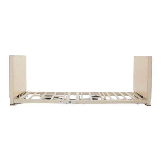
- Page 5 4. Installing bed boards as per Figure # 5. Figure # 5 Page 5...
-
Page 6: Motor Assembly
5. Connecting motor wires Insert the motor wire joint into the wire connecting hole of control box as per Figure # 6. Put the plastic cover on as per Figure # 7 Motor wire for head part Motor wire for foot part Hand control wire Motor wire for height Motor wire for height adjustment... -
Page 7: Operating The Bed
IMPORTANT: TO AVOID DAMAGE TO THE POWER CORD, PLEASE MAKE SURE TO PLACE THE POWER CORD THROUGH BOTH RINGS AS PER Figure #7A BEFORE OPERATING THE BED. Figure # 7A Placing the power cord through the ring as per Figure # 7B: Figure # 7B Page 7... - Page 8 6. Operating the Remote Control / Hand Pendant Ensure the power cord is connected properly. The patient can easily control all 5 functions by using the remote hand pendant. This includes adjusting the bed height, raising/lowering the head and foot sections, trendelenburg and reverse trendelenburg. Press the remote control button until the ideal position is reached.
- Page 9 8. Bed Mattress Retainer Installation Hang the Bed Mattress Retainer on the rectangular tubes of the mattress decks (see figures # 10) Figure # 10 9. Rotating Assist Bar Installation & use 9.1.1 Insert the rail rods into the rail holes (see figures # 11) Figure # 11 Page 9...
- Page 10 9.1.2 Secure the Rail rods to the bed by inserting the securing pins to the rod (see figures # 12) Figure # 12 9.2.Repeat the above installation, Step 1, to install the Pivot Assist Bar on the other side. 9.3.Pivot Assist Bar is used as an assist device to help the patient transfer in and out of bed To raise the Assist Bar: Pull up the Assist Bar until it clicks in place.
- Page 11 WARNING Only use Medacure approved side rails with this bed. Other manufacturers assist bars and side rails may not be compatible and can lead to entrapment issues or harm to patients.
Need help?
Do you have a question about the SUPER LOW BED 3.9 and is the answer not in the manual?
Questions and answers