
Related Manuals for MedaCure LX-BARI


Summary of Contents for MedaCure LX-BARI
- Page 1 U S E R M A N U A L SERIES MODEL # LX-BARI & LX-BARI-9 IMPORTANT: CHECK THE LABEL ON THE BED FRAME FOR THE CORRESPONDING MODEL NUMBER © 2021 MADE IN CHINA...
-
Page 2: Table Of Contents
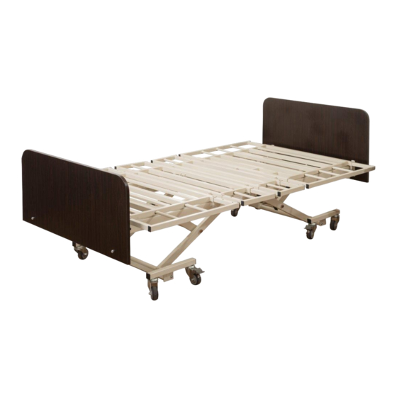
TABLE OF CONTENTS INRODUCTION & RODUCT FEATURES PAGE 2 PAGE 3 PARTS LIST AND DESCRIPTION INSTALLLING THE LIFTING FRAME PAGE 4 & HEIGHT ADJUSTMENT MOTOR INSTALLING THE LENGTH EXTENSION FRAME PAGE 5 INSTALLING B ED BOARDS PAGE 6-8 PAGE 8 WIRING T HE NURSE C ONTROL CASTERS PAGE 9... - Page 3 Device. The plug and the motors are IP43 rated. Durable and built to last with all steel construction and removable head & foot boards. The LX-BARI is a sturdy bed with multi-functional features and an attractive upscale design that will enhance the décor of any room.
-
Page 4: Parts List And Description
PARTS LIST & DESCRIPTION IMPORTANT: Read this manual completely before setting up or operating this system and keep in a safe place for future reference. To avoid injury and for maximum safety, this system should only be installed by an authorized technician or dealer representative. Electric bed installation parts listed below as per Figure # 1 Bed frame Bed foot board (with... -
Page 5: Installling The Lifting Frame
1. Installing the lifting frame Remove theφ13.5 bolt from the lifting frame (1). Place aφ14 plastic washer between the lifting frame (1) and lifting frame (2), matching the bolt holes on both lifting frames. Fasten with a φ 13.5 bolt with cotter pin as per Figure # 2. Use 4 bolts to connect the lifting frames. φ13.5 Bolt φ14 Plastic washer... -
Page 6: Installing The Length Extension Frame
Installing the length extension frame 3.1. Insert extension frame (left) & extension frame (right) into the 60 x 30 mm rectangular bed frame tube. See Figure # 4 The extension frame tubes should face upward. Insert the extension frame, tighten the bolt to lock the extension frame, and then fix the plastic head bolt. -
Page 7: Installing B Ed Boards
4. Installing the bed boards 4.1 Press the M8 × 18 plate nut into the bed board holes, as per Figure # 6. Figure # 6 4.2.1 Match the bed head board with the bed frame installation holes. Fasten by M8 X 20 cup head bolt with φ... - Page 8 Unfolded Position Folded Position Figure # 7.1 4.3 Match the bed foot board with the extension frame installation holes. Fasten by M8 X 20 cup head bolt with φ 8 flat washer. Bed foot board can be installed in both the high and low level position. See Figure # 8 & Figure # 9. Figure # 8 Bed foot board in low-level installation position P a g e...
- Page 9 Figure # 9 Bed foot board in high-level installation position 4.4 Install the bed head board to the bed head frame, and bed foot board to the bed foot frame, as per Figure # 10. Figure # 10 P a g e...
-
Page 10: Casters
5. Casters There are 4 pcs. locking casters and 4 pcs. swivel casters per set. Step on the locking pedal (lower) to activate the locking position and step on the unlocking pedal (upper) to deactivate the locking system. See Figure # 12 & 13. Step on the pedal to lock Step on the pedal to the caster in place... - Page 11 6.2 IMPORTANT NOTE: There are 3 location holes on each extension frame for 3 width adjustment settings - 36”, 42” and 48” widths. There are 4 separate extension frames on each side of the main frame. Repeat the above method in 6.1 to achieve the desired width and then tighten the “Locking Bolt”...
-
Page 12: Bumper Guard Installation And Usage
8. Each corner of the bed frame has two mattress retainer installation holes. Insert the mattress retainer as noted in Figure # 16.1. Mattress Retainer Installation for Standard Bed Deck Mattress Retainer Installation for Expandable Bed Deck Figure # 16.1 Bumper Guard Installation and Usage There are two retractable rubber Bumper Guards on the head of the bed. - Page 13 Figure # 16.4 Figure # 16.4 10. Side Rails and Assist Bars 10.1. Medacure has multiple side rail and assist bar options. Please contact your dealer or authorized representative for details. For rail entrapment guidelines please visit the FDA.Gov website...
-
Page 14: Patien R T Emote Handset
11. Patient remote handset Raise bed head part Lower bed head part Raise bed foot part Lower bed foot part Raise both bed head Lower both bed head and foot part and foot part Lower the entire bed Raise the entire bed Reverse Trendelenburg Trendelenburg Figure # 17 Trendelenburg position...
Need help?
Do you have a question about the LX-BARI and is the answer not in the manual?
Questions and answers