Table of Contents
Advertisement
Quick Links
Advertisement
Table of Contents

Related Manuals for EWM Phoenix 352 puls MM


Summary of Contents for EWM Phoenix 352 puls MM
- Page 1 Operating instructions Power sources for automated applications Phoenix 352 puls MM Phoenix 452 puls MM Phoenix 552 puls MM 099-005376-EW501 Observe additional system documents! 18.07.2014 Register now! For your benefit Jetzt Registrieren und Profitieren! www.ewm-group.com...
- Page 2 +49 2680 181-0. A list of authorised sales partners can be found at www.ewm-group.com. Liability relating to the operation of this equipment is restricted solely to the function of the equipment. No other form of liability, regardless of type, shall be accepted.
-
Page 3: Table Of Contents
Contents Notes on the use of these operating instructions Contents 1 Contents ..............................3 2 Safety instructions ..........................6 Notes on the use of these operating instructions ................6 Explanation of icons ........................7 General ............................8 Transport and installation ......................12 2.4.1 Lifting by crane ...................... - Page 4 Contents Notes on the use of these operating instructions 5.14.5 Automation interface ..................... 45 5.14.6 Sensor Voltage ......................47 5.15 Protecting welding parameters from unauthorised access ............48 5.15.1 Welding data display ..................... 48 5.16 Definition of MIG/MAG welding tasks ..................49 5.16.1 Welding task selection ....................
- Page 5 Cooling units ..........................80 10 Circuit diagrams ........................... 81 10.1 Phoenix 352, 452, 552 puls MM ....................81 11 Appendix A ............................83 11.1 JOB-List ............................83 12 Appendix B ............................92 12.1 Overview of EWM branches ......................92 099-005376-EW501 18.07.2014...
-
Page 6: Safety Instructions
Safety instructions Notes on the use of these operating instructions Safety instructions Notes on the use of these operating instructions DANGER Working or operating procedures which must be closely observed to prevent imminent serious and even fatal injuries. • Safety notes include the "DANGER" keyword in the heading with a general warning symbol. •... -
Page 7: Explanation Of Icons
Safety instructions Explanation of icons Explanation of icons Symbol Description Press Do not press Turn Switch Switch off machine Switch on machine ENTER (enter the menu) ENTER ENTER NAVIGATION (Navigating in the menu) NAVIGATION EXIT (Exit the menu) EXIT Time display (example: wait 4s/press) Interruption in the menu display (other setting options possible) Tool not required/do not use Tool required/use... -
Page 8: General
Safety instructions General General DANGER Electric shock! Welding machines use high voltages which can result in potentially fatal electric shocks and burns on contact. Even low voltages can cause you to get a shock and lead to accidents. • Do not touch any live parts in or on the machine! •... - Page 9 Safety instructions General WARNING Explosion risk! Apparently harmless substances in closed containers may generate excessive pressure when heated. • Move containers with inflammable or explosive liquids away from the working area! • Never heat explosive liquids, dusts or gases by welding or cutting! Smoke and gases! Smoke and gases can lead to breathing difficulties and poisoning.
- Page 10 Safety instructions General CAUTION Obligations of the operator! The respective national directives and laws must be observed for operation of the machine! • National implementation of the framework directive (89/391/EWG), as well as the associated individual directives. • In particular, directive (89/655/EWG), on the minimum regulations for safety and health protection when staff members use equipment during work.
- Page 11 Safety instructions General CAUTION EMC Machine Classification In accordance with IEC 60974-10, welding machines are grouped in two electromagnetic compatibility classes (see technical data): Class A machines are not intended for use in residential areas where the power supply comes from the low-voltage public mains network.
-
Page 12: Transport And Installation
Safety instructions Transport and installation Transport and installation WARNING Incorrect handling of shielding gas cylinders! Incorrect handling of shielding gas cylinders can result in serious and even fatal injury. • Observe the instructions from the gas manufacturer and in any relevant regulations concerning the use of compressed air! •... -
Page 13: Lifting By Crane
Safety instructions Transport and installation 2.4.1 Lifting by crane WARNING Risk of injury during lifting by crane When lifting the machine by crane, persons may be severely injured by falling machines or mount-on components. • Simultaneous lifting of system components such as power source wire feeder or cooling unit is not allowed. -
Page 14: Ambient Conditions
Safety instructions Transport and installation 2.4.2 Ambient conditions CAUTION Installation site! The machine must not be operated in the open air and must only be set up and operated on a suitable, stable and level base! • The operator must ensure that the ground is non-slip and level, and provide sufficient lighting for the place of work. -
Page 15: Intended Use
EWM welding processes offers many possibilities. Welding performance can be represented as average value (ex works) or solely as program A value. If the average value display is activated the signal lights of the main (PA) and reduced main program (PB) are illuminated simultaneously. -
Page 16: Use And Operation Solely With The Following Machines
Intended use Use and operation solely with the following machines Use and operation solely with the following machines Phoenix Phoenix Phoenix Phoenix Phoenix Phoenix Phoenix Phoenix 352 puls 352 puls 452 puls 452 puls 552 puls 552 puls 1002 puls 1002 puls MM RC MM RC... -
Page 17: Documents Which Also Apply
Intended use Documents which also apply Documents which also apply 3.3.1 Warranty NOTE For further information, please see the accompanying supplementary sheets "Machine and Company Data, Maintenance and Testing, Warranty"! 3.3.2 Declaration of Conformity The designated machine conforms to EC Directives and standards in terms of its design and construction: •... -
Page 18: Machine Description - Quick Overview
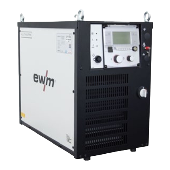
Machine description – quick overview Front view Machine description – quick overview Front view Figure 4-1 099-005376-EW501 18.07.2014... - Page 19 Machine description – quick overview Front view Item Symbol Description Lifting lug PC interface, serial (D-Sub connection socket, 9-pole) Machine control "See 4.3 Machine control – Operating elements chapter“ Main switch, machine on/off Cooling air inlet Machine feet 099-005376-EW501 18.07.2014...
-
Page 20: Rear View
Machine description – quick overview Rear view Rear view Figure 4-2 099-005376-EW501 18.07.2014... - Page 21 Machine description – quick overview Rear view Item Symbol Description Interfaces (customer specific) • RINTX12 robot interface • BUSINTX11 industrial bus interface 19-pole mechanised welding interface (analogue) "See 5.14.5 Automation interface chapter" 8-pole connection socket Cooling unit control lead 7-pole connection socket (digital) For connecting digital accessory components 7-pole connection socket (digital) Wire feed unit connection...
-
Page 22: Machine Control - Operating Elements
Machine description – quick overview Machine control – Operating elements Machine control – Operating elements NOTE The device controller may be installed both in an external wired remote Control as well as in the power source! Figure 4-3 Item Symbol Description Buttons switching digital display, left Welding current (nominal, actual and hold values) - Page 23 Machine description – quick overview Machine control – Operating elements Item Symbol Description Key switch for protection against unauthorised use Position “1” > changes possible, Position “0” > changes not possible. "See 5.15 Protecting welding parameters from unauthorised access chapter". "JOB Manager"...
-
Page 24: Design And Function
Design and function General Design and function General WARNING Risk of injury from electric shock! Contact with live parts, e.g. welding current sockets, is potentially fatal! • Follow safety instructions on the opening pages of the operating instructions. • Commissioning may only be carried out by persons who have the relevant expertise of working with arc welding machines! •... - Page 25 Design and function General CAUTION Damage due to incorrect connection! Accessory components and the power source itself can be damaged by incorrect connection! • Only insert and lock accessory components into the relevant connection socket when the machine is switched off. •...
-
Page 26: Connection Plan
Design and function Connection plan Connection plan M Drive 4 Rob 2 Fassförderung SPS / CU / ROB RINTX12 BUSINTX11 Cool 82 Figure 5-1 099-005376-EW501 18.07.2014... -
Page 27: Legend
Design and function Connection plan 5.2.1 Legend Wire feed Welding current (minus potential, workpiece) Shielding gas Welding torch coolant Cooling water input Cooling water output Welding machine supply voltage Welding current (plus potential) 19-pole mechanised welding interface Wire feed unit control lead (12-pole) Wire feed unit control lead/RINTX12, BUSINTX11 (7-pole) Cooling unit supply voltage connection (5-pole) Euro torch connector... -
Page 28: Installation
Design and function Installation Installation CAUTION Installation site! The machine must not be operated in the open air and must only be set up and operated on a suitable, stable and level base! • The operator must ensure that the ground is non-slip and level, and provide sufficient lighting for the place of work. -
Page 29: Notes On The Installation Of Welding Current Leads
Design and function Notes on the installation of welding current leads Notes on the installation of welding current leads NOTE Incorrectly installed welding current leads can cause faults in the arc (flickering). Lay the workpiece lead and hose package of power sources without HF igniter (MIG/MAG) for as long and as close as possible in parallel. - Page 30 Design and function Notes on the installation of welding current leads NOTE Use an individual welding lead to the workpiece for each welding machine! Figure 5-3 NOTE Fully unroll welding current leads, torch hose packages and intermediate hose packages. Avoid loops! Always keep leads as short as possible! Lay any excess cable lengths in meanders.
-
Page 31: Welding Torch Cooling System
Design and function Welding torch cooling system Welding torch cooling system CAUTION Coolant mixtures! Mixtures with other liquids or the use of unsuitable coolants result in material damage and renders the manufacturer's warranty void! • Only use the coolant described in this manual (overview of coolants). •... -
Page 32: Mains Connection
Design and function Mains connection Mains connection DANGER Hazard caused by improper mains connection! An improper mains connection can cause injuries or damage property! • Only use machine with a plug socket that has a correctly fitted protective conductor. • If a mains plug must be fitted, this may only be carried out by an electrician in accordance with the relevant national provisions or regulations! •... -
Page 33: Intermediate Hose Package Connection
Design and function Intermediate hose package connection Intermediate hose package connection NOTE Note the polarity of the welding current! Some wire electrodes (e.g. self-shielding cored wire) are welded using negative polarity. In this case, the welding current lead should be connected to the "-" welding current socket, and the workpiece lead should be connected to the "+"... -
Page 34: Matching The Cable Resistance
Design and function Matching the cable resistance 5.10 Matching the cable resistance The resistance value of cables can either be set directly or it can be matched using the power source. The factory setting of the power sources is 8 m-ohm. This value correponds to a 5 m earth cable, a 1.5 m intermediate hose package and a 3 m water-cooled welding torch. - Page 35 Design and function Matching the cable resistance 1 Preparation • Switch off the welding machine. • Unscrew the gas nozzle of the welding torch. • Cut off the welding wire to be flush with the contact tip. • Retract the welding wire a bit (approx. 50 mm) on the wire feeder. Now there should be no more welding wire in the contact tip.
-
Page 36: Connection For Workpiece Lead
Design and function Connection for workpiece lead 5.11 Connection for workpiece lead NOTE Note the polarity of the welding current! Some wire electrodes (e.g. self-shielding cored wire) are welded using negative polarity. In this case, the welding current lead should be connected to the "-" welding current socket, and the workpiece lead should be connected to the "+"... -
Page 37: Connect The Cooling Module To The Power Source
Design and function Connect the cooling module to the power source 5.12 Connect the cooling module to the power source NOTE Please note the relevant documentation of the accessory components. Figure 5-9 Item Symbol Description 8-pole connection socket Cooling unit control lead Connection socket, 5-pole Cooling unit voltage supply •... -
Page 38: Shielding Gas Supply (Shielding Gas Cylinder For Welding Machine)
Design and function Shielding gas supply (shielding gas cylinder for welding machine) 5.13 Shielding gas supply (shielding gas cylinder for welding machine) 5.13.1 Connecting the shielding gas supply WARNING Incorrect handling of shielding gas cylinders! Incorrect handling of shielding gas cylinders can result in serious and even fatal injury. •... -
Page 39: Setting Instructions
Design and function Shielding gas supply (shielding gas cylinder for welding machine) Figure 5-10 Item Symbol Description Pressure regulator Shielding gas cylinder Output side of the pressure regulator Cylinder valve • Place the shielding gas cylinder in the cylinder holder and secure it from tipping over using the securing chain! Before connecting the pressure regulator to the gas cylinder, open the cylinder valve briefly to blow out •... -
Page 40: Interfaces
Design and function Interfaces 5.14 Interfaces 5.14.1 Connecting the RINT X11 robot interface/BUSINT X11 industrial bus interface CAUTION Damage due to the use of non-genuine parts! The manufacturer's warranty becomes void if non-genuine parts are used! • Only use system components and options (power sources, welding torches, electrode holders, remote controls, spare parts and replacement parts, etc.) from our range of products! •... - Page 41 Design and function Interfaces Figure 5-11 Item Symbol Description 7-pole connection socket (digital) For connecting digital accessory components Switching cabinet Robot interface, Tetrix / Phoenix / alpha Q, RINT X12 Industrial bus interface, Tetrix / Phoenix / alpha Q, BUSINT X11 Interface casing Connection cable, 7-pole Connection between switching cabinet and power source...
-
Page 42: Connecting The Pc 300.Net Welding Parameterisation Software
Design and function Interfaces 5.14.2 Connecting the PC 300.net welding parameterisation software Create all welding parameters quickly on the PC and easily transfer them to one or more welding machines (accessories, set consisting of software, interface, connection leads) Figure 5-12 Item Symbol Description PC interface, serial (D-Sub connection socket, 9-pole) -
Page 43: Connecting The Q-Doc 9000 Welding Data Documentation Software
Design and function Interfaces 5.14.3 Connecting the Q-DOC 9000 welding data documentation software (Accessories: Set consisting of software, interface, connection leads) The ideal tool for welding data documentation of, for example: welding voltage and current, wire speed and motor current. Figure 5-13 Item Symbol Description... -
Page 44: Connecting The Weldqas Welding Data Monitoring And Documentation System
Design and function Interfaces 5.14.4 Connecting the WELDQAS welding data monitoring and documentation system Network-compatible welding data monitoring and documentation system for digital power sources. Figure 5-14 Item Symbol Description 7-pole connection socket (digital) For connecting digital accessory components Windows PC WELDQAS welding data monitoring and documentation system Connection cable, 7-pole Connection between switching cabinet and power source... -
Page 45: Automation Interface
Design and function Interfaces 5.14.5 Automation interface The welding power sources feature a very high safety standard. This safety standard is also maintained when peripheral equipment is connected for mechanised welding, if this peripheral equipment meets the same criteria, particularly with regard to isolation from the mains supply. - Page 46 Design and function Interfaces 19-pole connection assignment for mechanised welding interface (X4): Input/output Designation Note Output Cable screen connection Output REGaus Input Gasdüsensensor 1 Output IGR0 Maximum load 100 mA Current flowing signal (I>0) Not isolated! 0 V = welding current 15 V = no welding current Not-Aus Input...
-
Page 47: Sensor Voltage
Design and function Interfaces 12-pole connection assignments for mechanised welding interface (X2): Signalshape Circuit diagram signal Function name Input Not-Aus Emergency stop for higher level shut-down of the power source. To use this function, jumper 1 must be unplugged on PCB M320/1 in the welding machine. -
Page 48: Protecting Welding Parameters From Unauthorised Access
Design and function Protecting welding parameters from unauthorised access 5.15 Protecting welding parameters from unauthorised access To protect against unauthorised or unintentional adjustment of the welding parameters on the machine, the control input can be locked with the aid of a key switch. In key switch position 1 all functions and parameters can be set without restriction. -
Page 49: Definition Of Mig/Mag Welding Tasks
Design and function Definition of MIG/MAG welding tasks 5.16 Definition of MIG/MAG welding tasks The user defines the welding tasks using job numbers. Each job number stores all the parameters relating to the welding task. For the most commonly used applications, 128 pre-programmed JOBs (welding tasks) are stored in the machine control with the relevant parameters. -
Page 50: Welding Task Selection
Design and function Definition of MIG/MAG welding tasks 5.16.1 Welding task selection 5.16.1.1 Selecting or defining a new job Option 1: Select job from existing job reference list To do this, the job overview (see Appendix 2) is used as a reference for determining the welding task. It is also possible to use the "Job list"... -
Page 51: Forcearc / Forcearc Puls
Design and function Definition of MIG/MAG welding tasks 5.16.2 forceArc / forceArc puls Heat-reduced, directionally stable and powerful arc with deep penetration for the upper power range. Figure 5-17 • Smaller included angle due to deep penetration and directionally stable arc •... -
Page 52: Coldarc / Coldarc Puls
Design and function Definition of MIG/MAG welding tasks 5.16.3 coldArc / coldArc puls Heat-reduced, low-spatter short arc for welding and brazing of thin metal sheets with low distortion and for root welding with excellent gap bridging properties. Figure 5-18 After selecting the coldArc process (see chapter “Selecting a MIG/MAG welding task”) the following properties are available: •... -
Page 53: Operating Mode
Design and function Definition of MIG/MAG welding tasks 5.16.3.1 Operating mode This parameter setting is specified by the robot control via the RINTX12 or BUSINTX11 robot interface (see documentation in the relevant interface description). The selected parameter is displayed on the status displays on the control panel. 5.16.4 Welding type This parameter setting is specified by the robot control via the RINTX12 or BUSINTX11 robot interface (see documentation in the relevant interface description). -
Page 54: Program Sequence
Design and function Definition of MIG/MAG welding tasks Operating Action Result Display element Select "Dynamics" Setting from -40 to +40. Control voltage operation This parameter setting is specified by the robot control via the RINTX12 or BUSINTX11 robot interface (see documentation in the relevant interface description). Signal light "PROG 0"... -
Page 55: Superpuls
Design and function Definition of MIG/MAG welding tasks 5.16.4.3 superPuls Figure 5-20 With superpulses, there is a changeover between the main program (P ) and reduced main program (P This function is used in the very thin metal sheet range, for example, to reduce the heat input in a targeted way. -
Page 56: Mig/Mag Functional Sequences / Operating Modes
Design and function Definition of MIG/MAG welding tasks 5.16.5 MIG/MAG functional sequences / operating modes NOTE There are optimum pre-sets for welding parameters such as gas pre-flow and burn back, etc. for numerous applications (although these can also be changed if required). 5.16.6 Explanation of signs and functions Symbol Meaning... - Page 57 Design and function Definition of MIG/MAG welding tasks Non-latched mode Figure 5-21 Step 1 • Robot issues the start signal to the power source. • Shielding gas is expelled (gas pre-flows). • Wire feed motor runs at “creep speed”. • Arc ignites after the wire electrode makes contact with the workpiece;...
- Page 58 Design and function Definition of MIG/MAG welding tasks Non-latched operation with superpulse NOTE Pulse arc welding machines only. Figure 5-22 Step 1 • Robot issues the start signal to the power source. • Shielding gas is expelled (gas pre-flows). • Wire feed motor runs at “creep speed”.
- Page 59 Design and function Definition of MIG/MAG welding tasks Special, non-latched Figure 5-23 Step 1 • Robot issues the start signal to the power source. • Shielding gas is expelled (gas pre-flows) • Wire feed motor runs at “creep speed”. • Arc ignites after the wire electrode makes contact with the workpiece, welding current is flowing (start program P for the time t...
- Page 60 Design and function Definition of MIG/MAG welding tasks Special, non-latched with superpulse NOTE Pulse arc welding machines only. Figure 5-24 Step 1 • Robot issues the start signal to the power source. • Shielding gas is expelled (gas pre-flows) • Wire feed motor runs at “creep speed”.
-
Page 61: Mig/Mag Program Sequence ("Program Steps" Mode)
Design and function Definition of MIG/MAG welding tasks 5.16.7 MIG/MAG program sequence ("Program steps" mode) Certain materials, such as aluminium, require special functions in order to be able to weld them safely and at high quality. The non-latched special operating mode is used here with the following programs: •... -
Page 62: Main Program A Mode
Design and function Definition of MIG/MAG welding tasks Basic parameters Display Meaning / explanation Setting range GASstr Gas pre-flow time 0.0s to 0.9s RUECK Wire burn-back length 2 to 500 GASend: Gas post-flow time 0.0s to 20s Proc.Sp. Process speed to determine the a-measurement 10cm to 200cm "P "... -
Page 63: Mig/Mag Overview Of Parameters For M3.1X
Design and function Definition of MIG/MAG welding tasks 5.16.11 MIG/MAG overview of parameters for M3.1x Different welding tasks or positions on a workpiece demand various welding outputs (operating points) or welding programs. For each program, the • Wire speed • Correction of the arc length and the •... -
Page 64: Special Mode" Mode
Design and function "Special Mode" mode 5.17 "Special Mode" mode 5.17.1 Selection NOTE Combination of buttons shown must be selected without pauses! Operating Action Result Display element Select Special Mode Program Steps Special Mode 099-005376-EW501 18.07.2014... -
Page 65: Switching The Hold Function On And Off
Design and function "Special Mode" mode 5.17.2 Switching the Hold function on and off NOTE There is the option of switching the Hold function on and off for welding parameters. Operating Action Result Display element Hold-Fct Select the Hold function using the buttons "Up"... -
Page 66: Job Info" Mode
Design and function "Job Info" mode 5.18 "JOB Info" mode NOTE Information on the current JOB is displayed in this mode. • In JOBs 127 and 128 (TIG & MMA), it is not possible to select the mode as it would not be relevant. -
Page 67: Organising Welding Tasks (Mode "Job Manager")
Design and function Organising welding tasks (Mode "JOB Manager") 5.20 Organising welding tasks (Mode "JOB Manager") NOTE The Job Manager can be used to load, copy or save JOBs. The JOB is the welding task defined by the 4 main welding parameters; welding process, material type, wire diameter and gas type. -
Page 68: Loading An Existing Job
Design and function Organising welding tasks (Mode "JOB Manager") 5.20.2 Loading an existing job NOTE This function is used, for example, if the welding task (JOB) has been selected from the JOB reference list (see Appendix). Operating Action Result Display element Select JOB Manager mode JOB Manager... -
Page 69: Expert Parameters
Design and function Expert parameters 5.21 Expert parameters 5.21.1 Selecting expert model parameters Operating Action Result element Select expert model parameters 5.21.2 Selecting variables (5 model points) Operating Action Result element Select model points 1 to 5 5.21.3 Setting parameters Operating Action Result... -
Page 70: Maintenance, Care And Disposal
Maintenance, care and disposal General Maintenance, care and disposal DANGER Do not carry out any unauthorised repairs or modifications! To avoid injury and equipment damage, the unit must only be repaired or modified by specialist, skilled persons! The warranty becomes null and void in the event of unauthorised interference. •... -
Page 71: Monthly Maintenance Tasks
Maintenance, care and disposal Maintenance work 6.2.2 Monthly maintenance tasks 6.2.2.1 Visual inspection • Casing damage (front, rear and side walls) • Wheels and their securing elements • Transport elements (strap, lifting lugs, handle) • Check coolant tubes and their connections for impurities 6.2.2.2 Functional test •... -
Page 72: Disposing Of Equipment
In addition to this, returns are also possible throughout Europe via EWM sales partners. Meeting the requirements of RoHS We, EWM AG Mündersbach, hereby confirm that all products supplied by us which are affected by the RoHS Directive, meet the requirements of the RoHS (Directive 2002/95/EC). -
Page 73: Rectifying Faults
Rectifying faults Checklist for rectifying faults Rectifying faults Checklist for rectifying faults NOTE The correct machine equipment for the material and process gas in use is a fundamental requirement for perfect operation! Legend Symbol Description Fault/Cause Remedy Coolant error/no coolant flowing ... - Page 74 Rectifying faults Checklist for rectifying faults Welding torch overheated Insufficient coolant flow Check coolant level and refill if necessary Eliminate kinks in conduit system (hose packages) Loose welding current connections Tighten power connections on the torch and/or on the workpiece ...
-
Page 75: Error Messages (Power Source)
Rectifying faults Error messages (power source) Error messages (power source) All products are subject to rigorous production checks and final checks. If, despite this, something fails to work at any time, please check the product using the following flowchart. If none of the fault rectification procedures described leads to the correct functioning of the product, please inform your authorised dealer. -
Page 76: Interface For Automated Welding
Rectifying faults Error messages (power source) Error Category Possible cause Remedy Error 18 Auxiliary drive/ Check auxiliary drive (Wf.Sl.) speedometer error tachogenerator not issuing signals. M3.51 defective > inform Service Legend for categories (error reset) a) The error message will disappear once the error has been rectified. b) The error message can be reset by pressing a key button: Welding machine control Key button... -
Page 77: Display Machine Control Software Version
Rectifying faults Display machine control software version Display machine control software version NOTE The query of the software versions only serves to inform the authorised service staff! ENTER Figure 7-1 Display Setting/selection List of the software Start of the automated process Software versions display ------- = System bus ID/printed circuit board... -
Page 78: Vent Coolant Circuit
Rectifying faults Vent coolant circuit Vent coolant circuit NOTE Coolant tank and quick connect coupling of coolant supply and return are only fitted in machines with water cooling. To vent the cooling system always use the blue coolant connection, which is located as deep as possible inside the system (close to the coolant tank)! Figure 7-2 099-005376-EW501... -
Page 79: Technical Data
Technical data Phoenix 352, 452, 552 puls MM Technical data NOTE Performance specifications and guarantee only in connection with original spare and replacement parts! Phoenix 352, 452, 552 puls MM Welding current setting range 5 A - 350 A 5 A - 450 A 5 A - 550 A Welding voltage setting range 14,3 V - 31,5 V... -
Page 80: Accessories
090-008275-00000 Computer communication Type Designation Item no. RC 300 EWM tablet PC incl. software, adapter and interface 090-008238-00002 PC300.Net PC300.Net welding parameter software kit incl. 090-008777-00000 cable and SECINT X10 USB interface QDOC9000 V2.0 Set consisting of interface, documentation software,... -
Page 81: Circuit Diagrams
Circuit diagrams Phoenix 352, 452, 552 puls MM Circuit diagrams 10.1 Phoenix 352, 452, 552 puls MM NOTE Original format circuit diagrams are located inside the machine. Figure 10-1 099-005376-EW501 18.07.2014... - Page 82 Circuit diagrams Phoenix 352, 452, 552 puls MM Figure 10-2 099-005376-EW501 18.07.2014...
-
Page 83: Job-List
Appendix A JOB-List Appendix A 11.1 JOB-List 099-005376-EW501 18.07.2014... - Page 84 Appendix A JOB-List 099-005376-EW501 18.07.2014...
- Page 85 Appendix A JOB-List 099-005376-EW501 18.07.2014...
- Page 86 Appendix A JOB-List 099-005376-EW501 18.07.2014...
- Page 87 Appendix A JOB-List 099-005376-EW501 18.07.2014...
- Page 88 Appendix A JOB-List 099-005376-EW501 18.07.2014...
- Page 89 Appendix A JOB-List 099-005376-EW501 18.07.2014...
- Page 90 Appendix A JOB-List 099-005376-EW501 18.07.2014...
- Page 91 Appendix A JOB-List 099-005376-EW501 18.07.2014...
-
Page 92: Overview Of Ewm Branches
Appendix B Overview of EWM branches Appendix B 12.1 Overview of EWM branches 099-005376-EW501 18.07.2014...
Need help?
Do you have a question about the Phoenix 352 puls MM and is the answer not in the manual?
Questions and answers