Table of Contents
Troubleshooting

Related Manuals for Eaton Cutler-Hammer RSS 36-SD-ST


Summary of Contents for Eaton Cutler-Hammer RSS 36-SD-ST
- Page 1 Intelligent Technologies Modbus to QCPort Adapter (D77D-EMA) Modbus TCP Serial Modbus RS485 Installation and User Manual January 2006 Supercedes November 2004 MN05002002E (C) For more information visit www.eatonelectrical.com/it...
- Page 2 The product discussed in this literature is subject to terms and conditions outlined in appropriate Eaton Electrical selling policies. The sole source governing the rights and remedies of any purchaser of this equipment is the relevant Eaton Electrical selling policy.
-
Page 3: Table Of Contents
Intelligent Technologies Modbus to QCPort Adapter Manual January 2006 Table of Contents PRODUCT OVERVIEW ESCRIPTION EATURES AND ENEFITS AFETY NVIRONMENTAL ATINGS PPROVALS ERTIFICATIONS ODBUS PECIFICATIONS ATALOG UMBERING YSTEM PHYSICAL FEATURES HYSICAL ESCRIPTION IMENSIONS OWER UPPLY EQUIREMENTS OPERATION ONNECT TO ODBUS Ethernet Ethernet Server Connections Serial Modbus RS485... - Page 4 Intelligent Technologies Modbus to QCPort Adapter Manual January 2006 Connections/Interconnects TROUBLESHOOTING AND MAINTENANCE ENEWAL ARTS ROUBLESHOOTING APPENDIX A: SUPPORTED MODBUS FUNCTION CODES 41 (65) HROUGH 42 (66) ESET ERVICES APPENDIX B: MODBUS EXCEPTION RESPONSES APPENDIX C: REGISTER MAPPING APPENDIX D MODBUS ADAPTER FAULT LIST TECHNICAL SUPPORT MN05002002E (C) For more information visit...
- Page 5 Intelligent Technologies Modbus to QCPort Adapter Manual January 2006 Table of Figures Figure 1 Ethernet Cabling ......................14 MN05002002E (C) For more information visit www.eatonelectrical.com Page 5...
-
Page 6: Product Overview
January 2006 Product Overview Description Eaton Electrical Intelligent Technologies (IT) D77 Modbus Adapter (D77D-EMA) has greatly increased the functionality of the IT communicating products, allowing monitoring and control for IT IO and IT motor control devices. The Adapter subscans the devices and then concentrates all their data into a single Modbus node. -
Page 7: Safety
January 2006 Safety The following safety statements relate to the installation, setup, and operation of the Eaton Electrical IT Modbus Adapter. Notice Make sure you read and understand the installation procedures in this manual before you attempt to operate or setup the equipment. -
Page 8: Environmental Ratings
Intelligent Technologies Modbus to QCPort Adapter Manual January 2006 Environmental Ratings Table 1: Environmental Ratings Category Description Specification Transportation Temperature -50°C to 80°C [-58°F to 176°F] and Storage Humidity 5 – 95% non-condensing Operating Temperature -25°C to 65°C [-13°F to 149°F] Humidity 5 –... -
Page 9: Modbus Specifications
Intelligent Technologies Modbus to QCPort Adapter Manual January 2006 Modbus Specifications Table 3: Modbus Specifications Register IO Scan Modbus Connections 10 Modbus TCP Connections (Sockets) Pass-through Port 2000 and 2001 1024 bytes input Max Modbus IO Size 1024 bytes output Serial Modbus RS485 Baud Rate 1200, 2400, 4800, 9600, 19.2K, 38.4K, 57.6K, 115.2K... -
Page 10: Physical Features
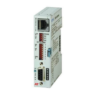
Intelligent Technologies Modbus to QCPort Adapter Manual January 2006 Physical Features Physical Description The following figure illustrates the various features of the IT Modbus Adapter (D77D- EMA). TCP LAN LED Modbus TCP Connection Adapter Status LED Serial Baud Rate and Module Status Mode Select Modbus TCP Network Status... -
Page 11: Dimensions
Intelligent Technologies Modbus to QCPort Adapter Manual January 2006 Dimensions The following figures illustrate the dimensions of the IT Modbus Adapter and ventilation space requirements for the device. [3.5] 22.5 68 [2.7] [.9] Table 7: Modbus Adapter (D77D-EMA) Dimensions, mm [in] Side Side Bottom... -
Page 12: Power Supply Requirements
Intelligent Technologies Modbus to QCPort Adapter Manual January 2006 Power Supply Requirements Power from multiple sources is required for operation of the Modbus Adapter. The Modbus Adapter CPU operates from power supplied on QCPort Channel A. The isolation between QCPort and Modbus is performed at the Modbus communication processor. -
Page 13: Operation
Intelligent Technologies Modbus to QCPort Adapter Manual January 2006 Operation This section provides details about the following features and aspects of D77D-EMA operation: • Connect to Modbus • Configuration Using CH Studio • Auto Configuration Overview Preparation Soft Configuration Hard Configuration •... -
Page 14: Connect To Modbus
Intelligent Technologies Modbus to QCPort Adapter Manual January 2006 Connect to Modbus There are two communication connections for the Modbus Adapter, they are Ethernet and the RS485. The Ethernet connection is 10 Base T and the RS485 connection is a DB9. - Page 15 Intelligent Technologies Modbus to QCPort Adapter Manual January 2006 Ethernet Addressing The Modbus Adapter supports addressing using a Static IP address and also using BOOTP (default). The following registers are used to setup and configure the TCP address. Table 10 TCP/IP Configuration Description Modbus Size...
-
Page 16: Serial Modbus Rs485
Intelligent Technologies Modbus to QCPort Adapter Manual January 2006 Serial Modbus RS485 The serial port uses the standard Serial Modbus RS485 connection, a DB9. Refer to the figure below for details on the pin out. Table 11: Modbus Connection Set the Serial Modbus Address The address and baud can only be set through the hardware. - Page 17 Intelligent Technologies Modbus to QCPort Adapter Manual January 2006 Set the Serial Modbus RS485 Baud Rate To set the baud rate for the serial Modbus, change the B0 through B2 DIP Switch settings. The following table displays valid baud rates. Table 13: Baud Rate Table Baud 1200...
-
Page 18: Configuration Using Ch Studio
The CH Studio tool is used for configuration, maintenance and monitoring of Eaton Electrical nodes and QCPort devices. After going on-line, using CH Studio, the Studio Explorer will display the Eaton Electrical nodes on Modbus and allow the user to “drill” down through the D77D-EMA to view and configure the QCPort devices. - Page 19 An unconfigured D77D-EMA with out an IP address will be visible from CH Studio due to a feature called Discovery that is build into each Eaton Electrical Ethernet Node. Once the node shows up on the explorer with in CH Studio, a temporary IP address is assigned to the D77D-EMA from the range of IP addresses in the TCP/IP network setup.
-
Page 20: General Tab
Intelligent Technologies Modbus to QCPort Adapter Manual January 2006 General Tab Once a Modbus node or QCPort device is selected, the Properties Window will display the attributes and parameters of that device. From this window, node/device parameters can be viewed and modified. This information is also contained within the Property Pages of the node/device that is being viewed by going to the toolbar and selecting View and then Property Pages (Shift + F4). -
Page 21: Configuration Tab
Intelligent Technologies Modbus to QCPort Adapter Manual January 2006 Configuration Tab The configuration tab is only used for setting up the Modbus Pass-Through parameters, if Modbus Pass-Through is not going to be used then it is not necessary to set any of these parameters. -
Page 22: Monitor Tab
Intelligent Technologies Modbus to QCPort Adapter Manual January 2006 Monitor Tab Once the D77D-EMA is configured, viewing the Monitor Tab will provide information as to the state of the D77D-EMA. Table 20 Monitor Tab MN05002002E (C) For more information visit www.eatonelectrical.com Page 22... -
Page 23: I/O Info Tab
Intelligent Technologies Modbus to QCPort Adapter Manual January 2006 I/O Info Tab The I/O Info Tab provides all the information as to the IO mapping of the connected QCPort devices. Not only will it give the order of the mapped IO, but also the register information for the inputs, outputs and the status registers for diagnostics. -
Page 24: Auto Configuration
Intelligent Technologies Modbus to QCPort Adapter Manual January 2006 Auto Configuration Overview When an auto configuration is performed, the D77D-EMA assembles the IO data into input data registers and output data registers for the devices on QCPort channels CHA and CHB. The data is assembled by QCPort channel and then in ascending order by device Group ID (address switch setting on device) using the default IO assembly for each device. -
Page 25: Soft Configuration
Intelligent Technologies Modbus to QCPort Adapter Manual January 2006 Soft Configuration Performing a soft configuration reconfigures the internal QCPort scan list to match all physically connected devices on CHA and CHB. It generates the register mappings that contain the IO information for these connected devices. To disable the auto configure (AC) push button refer to register 7556 in Appendix C: Register Mapping. -
Page 26: Hard Configuration
Intelligent Technologies Modbus to QCPort Adapter Manual January 2006 Hard Configuration Performing a Hard Configuration reconfigures the internal QCPort scan list to match all physically connected devices on CHA and CHB. It generates the Modbus IO register mappings that contain the input/output information for these connected devices. In addition, the QCPort device parameters for all devices on QCPort CHA and CHB are set to “factory default.”... -
Page 27: Scanning
Intelligent Technologies Modbus to QCPort Adapter Manual January 2006 Press and hold the Configuration Button for fiveseconds while applying power to QCPort to perform a Factory Configuration. Configures the Modbus IO registers for the Modbus Adapter and sets the QCPort device parameters to “factory default”... -
Page 28: Adding Or Removing Devices From Qcport
Intelligent Technologies Modbus to QCPort Adapter Manual January 2006 Notice With some PLC scanner cards it is important to stagger the scan rates when multiple connections are employed on one D77D-EMA. Adding or Removing Devices from QCPort If at any time devices are added or removed from QCPort, the IO registers will have to be revised using the Soft Configuration procedure or CH Studio. -
Page 29: Typical Application
Intelligent Technologies Modbus to QCPort Adapter Manual January 2006 Typical Application The following figure illustrates a typical Modbus Adapter application for a motor control center (MCC). In this application, the motor control (cover control units) is located on CHA. This application has many devices (not shown) on Modbus, and the Modbus Adapter is a single node on that network. - Page 30 Intelligent Technologies Modbus to QCPort Adapter Manual January 2006 Table 26 Modbus Addressing Output Coils Decimal Addressing Type Boolean Format 0xxxx Security Read/Write Range 1 - 65536 Input Coils Decimal Addressing Type Boolean Format 1xxxx Security Read Range 1 - 65536 Holding Registers Decimal Addressing Type...
-
Page 31: Floating Point Mapping
Intelligent Technologies Modbus to QCPort Adapter Manual January 2006 Floating Point Mapping Floating point data formats are 32 bit quantities; consequently, floating point numbers are stored in two consecutive registers. Table 27. IEEE-754 Floating Point Format Bit 31 Bits 30..23 Bits 22………………0 Sign Exponent... -
Page 32: Modbus Register Mapping
Intelligent Technologies Modbus to QCPort Adapter Manual January 2006 Modbus Register Mapping Table 29 Modbus Register Mapping Register Name Starting Register Length (Dec) Bytes (Dec) (Dec) Production Data (Read Only) 0x0001 (1) 0x0400 (1024) 0x0800 (2048) Consumption Data 0x0401 (1025) 0x0400 (1024) 0x0800 (2048) (Read/Write) - Page 33 Intelligent Technologies Modbus to QCPort Adapter Manual January 2006 Name Description Register 1025 Combined Channel A Channel B 0 – IO scan will not occur on the selected channel and all devices will exhibit their communication loss action Active Scan Channel and be offline.
-
Page 34: Status Registers
Intelligent Technologies Modbus to QCPort Adapter Manual January 2006 Channel Health Registers (Read) Table 31: Input Control Registers Name Description Register 2311 Channel A 0 – Selected channel not scanning Channel A Active 1 – Selected channel scanning 0 – Selected channel scan list registry requirements have been met Channel A Ready to Scan... - Page 35 Intelligent Technologies Modbus to QCPort Adapter Manual January 2006 Register 2305 - 2310 Modbus Adapter Faults These 6 registers will represent the fault index with in the Modbus Adapter. These fault registers are a bit representation of the Appendix D Modbus Adapter Fault List and are capable of indicating multiple faults at one time.
-
Page 36: Io Register Mapping
Intelligent Technologies Modbus to QCPort Adapter Manual January 2006 Register 2336 – 2339 Fault Bit Array Channel B Reading these 4 registers will provide feedback as to the state of the devices on QCPort Channel B, one bit for each device on the system. If the system only has 18 devices on Channel B, for example, only registers 2320 and 2321 need to be read. - Page 37 Intelligent Technologies Modbus to QCPort Adapter Manual January 2006 Example 1 Example 1 illustrates a typical MCC with factory IO configuration, for this example the MCC will have two buckets (cover control) of address 1 and 2. Each device has the following IO parameters.
- Page 38 Intelligent Technologies Modbus to QCPort Adapter Manual January 2006 Example 2 Example 1 illustrates a typical MCC with user defined IO configuration, for this example the MCC will have two buckets (cover control) of address 1 and 2 and one 8 point input module at address 3.
-
Page 39: Modbus Pass-Through
Intelligent Technologies Modbus to QCPort Adapter Manual January 2006 Modbus Pass-Through Connect Modbus Slaves to Channel A or B When one or both of the QCPort channels are reconfigured for Modbus, it will be required to wire the Modbus communication wires to the proper pins. If Channel B is used for the Modbus Pass-Through, the desired port if also using QCPort, then it is recommended to use a D77E-QPLR as the interface between the Modbus network and the D77D-EMA. -
Page 40: Pass-Through Setup
Intelligent Technologies Modbus to QCPort Adapter Manual January 2006 Notice When using wormhole, if the end device returns an exception response the D77D-EMA will respond to the master with a 0B indicating there is no response from the end Modbus device. Pass-Through Setup When configuring either Channel A or Channel B as a Pass-Through, it is important to set up the properties of the network so it matches the properties of the slave devices being... -
Page 41: Pass-Through On Ethernet Using Port 2000 And 2001
Intelligent Technologies Modbus to QCPort Adapter Manual January 2006 Pass-Through On Ethernet using port 2000 and 2001 It is possible to connect Modbus RTU slaves on QCPort Channel A and Channel B while QCPort devices are connected and scanning. This Pass-Through feature will slow the scan rate for that channel so it is recommended that if this feature is used, that all the Modbus devices be connected to a channel that is not scanning QCPort devices. - Page 42 Intelligent Technologies Modbus to QCPort Adapter Manual January 2006 Example Transmit Message Read Register 40111 (nominal frequency) from an SV drive SV drive address is 02 Read using function code 03 Message will be constructed: 0x01 for the Modbus node ID 0x03 for the function code 0x006E to read register 111 Notice...
-
Page 43: Pass-Through Using Registers
Intelligent Technologies Modbus to QCPort Adapter Manual January 2006 Pass-Through using Registers Modbus pass-through messages can be transmitted by writing to the Modbus Pass- Through special function registers. The first register in this series (offset 0) specifies the number of bytes in the Modbus message (CRC should not be included), and the second register in the series is the start of the message. - Page 44 Intelligent Technologies Modbus to QCPort Adapter Manual January 2006 Example Transmit Message Read Register 40111 (nominal frequency) from an SV drive SV drive address is 01 Read using function code 03 (read multiple holding registers) Notice Modbus is address based, not register based. The address is equal to 1 minus the register;...
-
Page 45: Status Leds
Intelligent Technologies Modbus to QCPort Adapter Manual January 2006 Status LEDs The status LED’s are located along left of the Modbus Adapter, as pictured in Table 4: Modbus Adapter (D77D-EMA) Front Features. The LED’s status changes depending on the state of the Modbus Adapter. The following tables list and describe the various states of the LAN, Modbus Adapter Status LEDs;... - Page 46 Intelligent Technologies Modbus to QCPort Adapter Manual January 2006 LED State Meaning TCP Network Status LED (NS) IF the MS LED is on or flashing, then the D77D-EMA does not have a valid IP address Flashing Green No Connection established Green A Connection has been established Device cannot communicate on the network (may have a...
-
Page 47: Installation
Intelligent Technologies Modbus to QCPort Adapter Manual January 2006 Installation This section provides details about the following features and aspects of D77D-EMA Installation: • Installation on a DIN Rail • Replace Existing Module • Connect to Devices Connections/Interconnects MN05002002E (C) For more information visit www.eatonelectrical.com Page 47... -
Page 48: Installation On Adin Rail
Intelligent Technologies Modbus to QCPort Adapter Manual January 2006 Installation on a DIN Rail Use one of the following two procedures to install the Adapter on a DIN rail: • Install on a DIN Rail (no backplane) • Install on DIN a Rail with backplane Install on a DIN Rail (No Backplane) Prepare Module for Installation The DIN rail locking tab is on the right middle of the Modbus Adapter. - Page 49 Intelligent Technologies Modbus to QCPort Adapter Manual January 2006 Install Module The module is now ready for installation on the DIN rail. Warning Do not “rock” the Modbus Adapter module onto the DIN rail. The rocking action could damage the module. 1.
-
Page 50: Install On Din Rail With Backplane
Intelligent Technologies Modbus to QCPort Adapter Manual January 2006 Install on DIN Rail With Backplane Prepare Module for Installation The DIN rail locking tab is on the right middle of the Modbus Adapter. When installing the Modbus Adapter on a DIN rail, verify that the slide of the DIN Rail Lock is extended to the unlocked position. - Page 51 Intelligent Technologies Modbus to QCPort Adapter Manual January 2006 Install Module The module is now ready for installation on the DIN rail. Warning Do not “rock” the Modbus Adapter module onto the DIN rail. The rocking action could damage the module. 1.
-
Page 52: Replace Existing Module
Intelligent Technologies Modbus to QCPort Adapter Manual January 2006 Replace Existing Module To replace an existing Modbus Adapter, first remove the old one. 1. Remove all connectors (Modbus and QCPort) from the Adapter. 2. Insert a screwdriver under the DIN rail locking tab and lift up to unlock the locking tab, as illustrated in the following figure. -
Page 53: Connect To Devices
Intelligent Technologies Modbus to QCPort Adapter Manual January 2006 Connect to Devices Connections/Interconnects Connecting the Modbus Adapter and other IT family products involves using one or more of the QCPort interconnects. The Modbus Adapter employs two types of connectors— one is the backplane interconnect and the other is the short run interconnect. These interconnects provide the QCPort products with both power and communications. - Page 54 Intelligent Technologies Modbus to QCPort Adapter Manual January 2006 Backplane Interconnect The backplane interconnect is used when connecting Adapter and IO products on a DIN rail. The interconnect fits inside the channel of the DIN rail and provides for connection of power and communication to Adapter and IO products.
-
Page 55: Troubleshooting And Maintenance
Intelligent Technologies Modbus to QCPort Adapter Manual January 2006 Troubleshooting and Maintenance Renewal Parts There are no renewal parts on the Modbus Adapter (D77D-EMA); the only related parts are the following accessories. Table 57: Accessories Part Number Description D77E-BP7 Expansion Backplane for 7 slots D77E-BP12 Expansion Backplane for 12 slots D77E-BP25... -
Page 56: Troubleshooting
Intelligent Technologies Modbus to QCPort Adapter Manual January 2006 Troubleshooting Use the following chart for assistance in troubleshooting the Modbus Adapter; the chart contains the most common faults and corrective actions. Table 58: Troubleshooting Chart Observation Possible Cause/Action None of the LEDs are Verify that power (24 VDC) is applied to the Modbus illuminated terminal and that power is on the QCPort channels. -
Page 57: Appendix A: Supported Modbus Function Codes
Intelligent Technologies Modbus to QCPort Adapter Manual January 2006 Appendix A: Supported Modbus Function Codes Access Type Description Code Data Access Physical Discrete Inputs Read Input Status 0x02 (2) Internal Bits or Physical Coils Read Coil status 0x01 (1) Force Single Coil 0x05 (5) Write Multiple Coils 0x0F (15) -
Page 58: Pass Through X
Intelligent Technologies Modbus to QCPort Adapter Manual January 2006 Pass Through 0x41 (65) Request PDU Function code 1 byte 0x41 QCPort Channel 1 byte 0 = channel A 1 = channel B QCPort request message n bytes Response PDU Function code 1 byte 0x41 QCPort response message... -
Page 59: Appendix B: Modbus Exception Responses
Intelligent Technologies Modbus to QCPort Adapter Manual January 2006 Appendix B: MODBUS Exception Responses When a client device sends a request to a server device it expects a normal response. One of four possible events can occur from the master’s query: •... - Page 60 Intelligent Technologies Modbus to QCPort Adapter Manual January 2006 Table 59-Modbus Exception Codes Code Name Meaning The function code received in the query is not an allowable action Illegal function for the server (or slave). This may be because the function code is only applicable to newer devices, and was not implemented in the unit selected.
-
Page 61: Appendix C: Register Mapping
Intelligent Technologies Modbus to QCPort Adapter Manual January 2006 Appendix C: Register Mapping Production (holding register area) Description Modbus Size Usage Read/ Register (Reg) Write QCPort Channel 0001 Status of QCPort channel A and B Status Production Data 1 0002 1023 Production Data area Device... - Page 62 Intelligent Technologies Modbus to QCPort Adapter Manual January 2006 Channel A Status (holding register area) Description Modbus Size Usage Read/ Register (Reg) Write Channel A status 2311 1 = Channel A Active 1 = Channel A Not Ready to Scan 1 = Faulted Device Channel A Reserved...
- Page 63 Intelligent Technologies Modbus to QCPort Adapter Manual January 2006 Channel B Status (holding register area) Description Modbus Size Usage Read/ Register (Reg) Write Channel B status 2327 1 = Channel B Active 1 = Channel B Not Ready to Scan 1 = Faulted Device Channel B Reserved...
- Page 64 Intelligent Technologies Modbus to QCPort Adapter Manual January 2006 Modbus Adapter Configuration (holding register area) Description Modbus Size Usage Read/ Register (Reg) Write Modbus Adapter 7505 This devices serial number Serial Number Modbus Adapter 7507 This devices hardware revision Hardware Revision number Modbus Adapter 7508...
- Page 65 Intelligent Technologies Modbus to QCPort Adapter Manual January 2006 Serial Modbus RS485 Configuration (holding register area) Description Modbus Size Usage Read/ Register (Reg) Write Serial Modbus 7539 The currently selected Serial RS485 Baud Rate Modbus RS485 baud. Uses Modbus Adapter baud rate enumerations. Serial Modbus 7540 The currently active Serial Modbus...
- Page 66 Intelligent Technologies Modbus to QCPort Adapter Manual January 2006 QCPort B Configuration (holding register area) Description Modbus Size Usage Read/ Register (Reg) Write Modbus Adapter 7549 Default 0xffff QCPort Device IDB QCPort Channel B 7551 9600 = 48 baud 19200 = 24 38400 = 12 57600 = 8 115200 = 4...
- Page 67 Intelligent Technologies Modbus to QCPort Adapter Manual January 2006 Auto Configuration (AC) Push Button Functionality (holding register area) Description Modbus Size Usage Read/ Register (Reg) Write AC Push Button 7556 0 – Disable Enable 1 – Enable (default) This setting is used to disable the use of the AC push button after a power up.
- Page 68 Intelligent Technologies Modbus to QCPort Adapter Manual January 2006 Dynamic Device Addition (DDA) Functions (Version 1.007 and later) Description Modbus Register Size Usage Read/ (Reg) Write CH A CH B DDA Produced Data 14494 14510 Sets the total consumed data size Allocated when using DDA.
-
Page 69: Appendix D Modbus Adapter Fault List
Intelligent Technologies Modbus to QCPort Adapter Manual January 2006 Appendix D Modbus Adapter Fault List Hard – Solid Red MS LED (Major Fault) Medium – Flashing Red MS LED (Recoverable Fault) Soft – Flashing Green MS LED (Minor Fault) Register 2305 (holding register area) Fault Fault Name Type... - Page 70 Intelligent Technologies Modbus to QCPort Adapter Manual January 2006 Register 2306 (holding register area) Fault Fault Name Type Fault Description Reserved QCPort Hard D77D-EMA can’t get QCPort channel A. 0x13 Channel A QCPort channel fault. Line may be oscillating Busy due to lack of termination or from a shorted line.
- Page 71 Intelligent Technologies Modbus to QCPort Adapter Manual January 2006 Register 2308 (holding register area) Fault Fault Name Type Fault Description Reserved Too Many Medium Too many devices were attached to the channel. 0x32 Devices connected to Channel A Too Many Medium Too many devices were attached to the channel.
- Page 72 Intelligent Technologies Modbus to QCPort Adapter Manual January 2006 Register 2309 (holding register area) Fault Fault Name Type Fault Description QCPort Medium A QCPort device has responded with a fault or a 0x40 Device Fault fault has been logged specific to a QCPort device.
-
Page 73: Technical Support
Intelligent Technologies Modbus to QCPort Adapter Manual January 2006 Technical Support For additional information on this product, Please call our Customer Support Center at: 1-800-356-1243 For service or start-up assistance 24 hours/day, 7 days/week, please call: 1-800-498-2678 MN05002002E (C) For more information visit www.eatonelectrical.com Page 73... - Page 74 Eaton has 51,000 employees and sell products in more than 50 controls. For more information visit www.eaton.com.
Need help?
Do you have a question about the Cutler-Hammer RSS 36-SD-ST and is the answer not in the manual?
Questions and answers