Code Blue CB 5 Series Admin Manual
Hide thumbs
Also See for CB 5 Series:
- Administrator's manual (50 pages) ,
- Administrator's manual (31 pages)

Related Manuals for Code Blue CB 5 Series


Summary of Contents for Code Blue CB 5 Series
- Page 1 CB5 Series Model: ENTS01, ENTS02, ENTS03, ENTS04 Admin Guide Installation | Configuration | Support | Maintenance | Use 800.205.7186 • www.codeblue.com...
- Page 2 OF OR IN CONNECTIONS WITH THIS GUIDE, THE SOFTWARE OR OTHER INFORMATION CONTAINED HEREIN OR THE USE THEREOF. Code Blue Corporation reserves the right to make any modifications to this guide or the information contained herein at any time without notice. The software described herein may also be governed by the terms of a separate user license agreement.
-
Page 3: Table Of Contents
Tools Needed Anchor Bolt Installation Instructions Deck Mount Kit Installation Instructions Base Gasket Installation Instructions CB 5 Series Installation Instructions Overhead Camera Mount Installation Instructions 360° Audio Paging Speaker Installation Instructions Remote Mount Beacon/Strobe Installation Instructions S-1000 & S-1050 Strobe Operation... -
Page 4: Introduction
CB 5 Series for your Code Blue application. CB 5 Series Help Points® are the original Code Blue pedestal units that set the industry standard for rugged construction, full feature availability and high visibility. The CB 5 Series is easily recognized throughout a full 360-degree area. The high output strobe is easily identifiable by security when activated. -
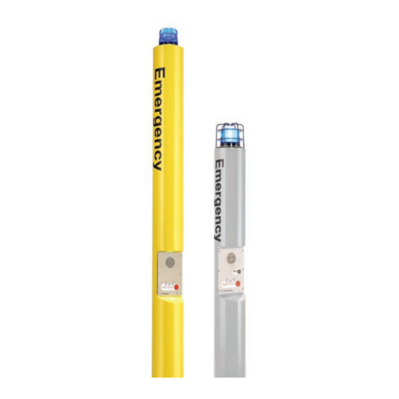
Page 5: Cb5 Series Model Photos
CB 5 Series Administrator Guide CB5 Series Model Photos This guide contains all of the CB 5 Series information. This guide contains a general overview of the CB 5 Series options and its applications, installation and wiring. CB 5-s CB 5-s... -
Page 6: Safety Instructions
In some countries, a certified electrician may be required. NOTICE When transporting a Code Blue product, use the original packaging or equivalent to prevent damage to the product. Code Blue products shall be used in compliance with local laws and regulations. -
Page 7: Installation Instructions
Important Notes: EIA/TIA, ANSI, CSA and BICSI cabling or similar standards shall be adhered to for proper operation of Code Blue communication devices connected to copper or fiber infrastructures communications cable and electrical cable in the same conduit is not an acceptable installation and shall not be supported. -
Page 8: Tools Needed
CB 5 Series Administrator Guide Tools Needed CB 5-s & CB 5-p Tools Required Ladder to reach the top of the units Drill and security bit for removing and inserting security screws on phone, dome top and access door 1-1/8" socket set and extension for installing anchor bolts or Deck Mount Kits... -
Page 9: Anchor Bolt Installation Instructions
1.3 Set the Anchor Bolts in the Wet Foundation – Three 24-inch L-shaped anchor bolts and an aligning template are supplied for anchoring the Code Blue unit. The bolts should be set into the foundation so that six inches are left showing above the finished grade level. -
Page 10: Deck Mount Kit Installation Instructions
CB 5 Series Administrator Guide Deck Mount Kit Installation Instructions SKIP if installation does not include a Deck Mount Kit 1.0 DECK MOUNT FOUNDATION 1.1 Drill Deck Holes– Drill three holes through the deck or floor for the three 3/4”... -
Page 11: Base Gasket Installation Instructions
CB 5 Series Administrator Guide Base Gasket Installation Instructions Access the mounting studs through the access door on the side of the unit. Set the gasket on the bolts and cut a small hole where the conduit is located. Stretch the screen tightly around the conduit pipe. Slide the gasket over the bolts to the base of unit. -
Page 12: Cb 5 Series Installation Instructions
Moisture problems may result if this condition is not complied with. 2.2 Set the Code Blue unit on the anchor bolts – Align the phone plate in the desired direction, then lift the Code Blue unit over the anchor bolts. Note that the unit weighs 180-220 pounds. - Page 13 CB 5 Series Administrator Guide Figure 1 Figure 2 All wiring must be installed and connected by experienced and certified personnel to meet local and national electrical codes, and will include a service disconnect. page 13 of 35 GU-158-O Code Blue •...
-
Page 14: Overhead Camera Mount Installation Instructions
CB 5 Series Administrator Guide Overhead Camera Mount Installation Instructions INSTALLING THE OVERHEAD CAMERA MOUNT The camera mount will come with a gasket already mounted to the bracket on the arm. Place the bracket over the mounting holes and insert the four 3/8-16 X 1 stainless bolts. (The 3/8”... -
Page 15: 360° Audio Paging Speaker Installation Instructions
3.1 After all of the connections are made, mount the Audio Paging unit onto the Audio Paging Adapter Code Blue CB 5 Pedestal Ring. Rotate to align the six holes and secure with the provided six #10-24 countersunk security screws. - Page 16 CB 5 Series Administrator Guide CB 5-S W/PAS AND OVERHEAD CAMERA MOUNT page 16 of 35 GU-158-O Code Blue • 259 Hedcor Street • Holland, MI 49423 USA • 800.205.7186 • www.codeblue.com...
-
Page 17: Remote Mount Beacon/Strobe Installation Instructions
CB 5 Series Administrator Guide Remote Mount Beacon/Strobe Installation Instructions ATTACH J-BOX TO THE POLE 1.1 Thread the banding (B) through the pole bracket (A) located on the backside of the J-box (C). 1.2 Wrap the banding around the pole. Cut the banding to desired length. -
Page 18: S-1000 & S-1050 Strobe Operation
CB 5 Series Administrator Guide S-1000 & S-1050 Strobe Operation NOTE: Instructions pertain to: Model S-1000 LED Beacon/Strobe and Model S-1050 LED Beacon/Strobe only. POSITIVE (12-24V DC or AC) BLACK COMMON (GROUND) YELLOW (FLASH MODE) CONTACT CLOSED = "ON" YELLOW (FLASH MODE) REMOVE ALL POWER FROM UNIT BEFORE SERVICING. - Page 19 CB 5 Series Administrator Guide PROGRAMMING PRIMARY & SECONDARY MODES 1. Remove power from unit. 2. Short the Yellow wires together. 3. Restore power to the unit and wait until the unit begins to flash. Once the unit begins to flash, remove the short. The unit will alternately demonstrate the Secondary-Flash Mode and Primary-Steadyburn Mode that will be displayed during operation.
-
Page 20: How To Replace Led Light Connectors
Administrator Guide How to Replace LED Light Connectors As of 2020, Code Blue strobe, area and faceplate lights come with Wago connectors. These connectors provide ease of use and a much stronger connection. Below are the steps needed to change to the new connectors. Each new LED light should come with both the plug-and-socket Wago connectors. - Page 21 CB 5 Series Administrator Guide Strip all wires and twist tight. Place small screwdriver into square hole and push down. Insert cut wire into round hole and remove screwdriver. Repeat on the rest of the connectors. Once all connectors have been switched, you are ready to apply power to the LED.
-
Page 22: Power Requirements
CB 5 Series Administrator Guide 5 Power Requirements The following tables on pages 22-25 include and ALL OTHER Code Blue devices & enclosures for reference. page 22 of 35 GU-158-O Code Blue • 259 Hedcor Street • Holland, MI 49423 USA •... - Page 23 CB 5 Series Administrator Guide page 23 of 35 GU-158-O Code Blue • 259 Hedcor Street • Holland, MI 49423 USA • 800.205.7186 • www.codeblue.com...
- Page 24 CB 5 Series Administrator Guide page 24 of 35 GU-158-O Code Blue • 259 Hedcor Street • Holland, MI 49423 USA • 800.205.7186 • www.codeblue.com...
- Page 25 CB 5 Series Administrator Guide page 25 of 35 GU-158-O Code Blue • 259 Hedcor Street • Holland, MI 49423 USA • 800.205.7186 • www.codeblue.com...
-
Page 26: Wiring Diagrams
CB 5 Series Administrator Guide 6 Wiring Diagrams 100-240 AC / DC or 24V AC @ 60 Watt or 24V DC page 26 of 35 GU-158-O Code Blue • 259 Hedcor Street • Holland, MI 49423 USA • 800.205.7186 •... -
Page 27: Poe Din Rail Power System | 48V Dc 12.96W Or 25.5W
CB 5 Series Administrator Guide PoE DIN Rail Power System | 48V DC 12.96w or 25.5w Product wiring diagram shown reasonably represents current offering and is intended to assist in component identification and service. Earlier product production may have different components and wiring connections. Reference the model and serial number from the unit ID tag and contact manufacturer to confirm replacement part version and availability. -
Page 28: 120-277V Ac Din Rail Power W/ 150W Audio Paging | 12 Or 24V Dc 10 Amps Max (Cb 5-S Only)
CB 5 Series Administrator Guide 120-277V AC DIN Rail Power w/ 150W Audio Paging | 12 or 24V DC 10 Amps Max (CB 5-s Only) Product wiring diagram shown reasonably represents current offering and is intended to assist in component identification and service. -
Page 29: Multi-Tap Transformer (Power Brick) 110-347Vac
CB 5 Series Administrator Guide Multi-Tap Transformer (Power Brick) 110-347VAC Product wiring diagram shown reasonably represents current offering and is intended to assist in component identification and service. Earlier product production may have different components and wiring connections. Reference the model and serial number from the unit ID tag and contact manufacturer to confirm replacement part version and availability. -
Page 30: Locating Serial Numbers
CB 5 Series Administrator Guide 7 Locating Unit Serial Numbers Remove the access plate cover with the special security bit. The serial number will be listed on the manufacturer’s label located on the backside of the access plate cover (1). -
Page 31: Maintenance Schedule
CB 5 Series Administrator Guide 8 Maintenance Schedule LEGEND Guard Tasks Technician Tasks DAILY OR WEEKLY Perform functional communications check. Action: Press Red Button Strobe activates Red LED "Call Placed" light turns on Message plays Call connects, green LED "Call Received" light turns on... - Page 32 The Surface Care Frequency table below provides general guidelines to assist in configuring a schedule. Please note that the frequency of care required to guard the Code Blue unit’s surface from damage will also be dictated by local environmental characteristics.
-
Page 33: Warranty
9 Warranty Code Blue Corporation provides a limited warranty on this product. Refer to your sales agreement to establish the terms. In addition, Code Blue’s standard warranty language, as well as information regarding support for this product while under warranty, is available at www.codeblue.com/support... -
Page 34: Download Information
CB 5 Series Administrator Guide 10 Download Information Code Blue now has a centralized location where you can find installation, setup, information, configuration and operation instructions. Admin Guides: www.codeblue.com/resources/guides Frimware: www.codeblue.com/resources/firmware Maintenance Tips: www.codeblue.com/support Product Sheets: www.codeblue.com/resources/sheets Specifications: www.codeblue.com/resources/specifications For Legacy Product Information: www.codeblue.com/legacy-products... -
Page 35: Legal & Regulatory Information
This digital apparatus complies with CAN ICES-3 (Class A). The product shall and fitness for a particular purpose. Code Blue shall not be liable or be connected using a shielded network cable (STP) that is properly responsible for incidental or consequential damages in connection with grounded.
Need help?
Do you have a question about the CB 5 Series and is the answer not in the manual?
Questions and answers