Code Blue CB 1 Series Administrator's Manual
Cb 1 series with public address, cb 1-w with solar/gsm/wireless
Hide thumbs
Also See for CB 1 Series:
- Administrator's manual (31 pages) ,
- Admin manual (32 pages) ,
- Admin manual (50 pages)

Related Manuals for Code Blue CB 1 Series


Summary of Contents for Code Blue CB 1 Series
- Page 1 CB 1 Series CB 1-e CB 1-s CB 1 Series with Public Address CB 1-w with Solar/GSM/Wireless Installation | Configuration | Operation | Troubleshooting Administrator Guide 800.205.7186 www.codeblue.com •...
- Page 2 OR OTHER INFORMATION CONTAINED HEREIN OR THE USE THEREOF. Code Blue Corporation reserves the right to make any modifications to this guide or the information contained herein at any time without notice. The software described herein may also be governed by the terms of a separate user license agreement.
-
Page 3: Table Of Contents
12 CB 1-s with Dual Faceplates High Voltage Exploded View..20 13 CB 1-w Exploded View..............21 14 CB 1-e and CB 1-s Installation Instructions........22 15 CB 1 Series Tower Base Gasket Installation Instructions..24 16 CB 1-s with AED Housing Installation Instructions....26 17 CB 1-w Installation Instructions...........28 18 Cellular Retro Instructions............31... - Page 4 35 CB 1-e 120V Standard Wiring Diagram ....62 (with Triad Transformer) 36 CB 1 Series NightCharge Wiring............63 37 CB 1 Series with Public Address Wiring.........64 38 CB 1-w Standard Wiring..............66 39 GSM Wireless Wiring Diagram............67 40 CB 1-s with AED, Public Address and IP Wireless......68 41 CB 1-s with AED Wiring..............69...
-
Page 5: Introduction
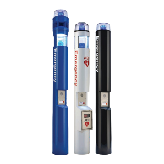
CB 1 Series for your Code Blue application. CB 1 Series of products are the original Code Blue pedestal units that set the industry CB 1 Series standard for rugged construction, full feature availability and high visibility. The is easily recognized throughout a full 360-degree area. - Page 6 CB 1 Series Administrator Guide This guide contains all of the CB 1 Series information for the CB 1-e, CB 1-s and the CB 1-w with WindAssist™. This guide contains a general overview of the CB 1 Series options and its application, installation and wiring.
-
Page 7: Getting Started
1. EIA/TIA, ANSI, CSA and BICSI cabling or similar standards shall be adhered to for proper operation of Code Blue communication devices connected to copper or fiber infrastructures. Communications cable and electrical cable in the same conduit is not an acceptable instal- lation and shall not be supported. - Page 8 CB 1 Series Administrator Guide CB 1-e and CB 1-s Tools Required 1. Ladder to reach the top of the units 2. Drill and security bit for removing and inserting security screws on phone, dome top and access door 3. 11/8 socket set and extension for installing anchor bolts or Deck Mount Kits 4.
-
Page 9: Spare Parts
CB 1 Series Administrator Guide 4 Spare Parts CB 1-e Part Part Number LED Strobe Light 40159 Dome Top Lens 41402 LED Faceplate Light 40196 Faceplate Screws 41544 (6pk) Dome Top Screws 41500 (3pk) Access Door Screws 41545 (2pk) Manifold R/B 5-way... - Page 10 CB 1 Series Administrator Guide CB 1-s Part Part Number LED Strobe Light 40159 Dome Top Lens 41402 LED Area Light 41539 LED Faceplate Light 40196 Faceplate Screws 41544 (6pk) Dome Top Screws 41500 (3pk) Access Door Screws 41545 (2pk)
- Page 11 CB 1 Series Administrator Guide CB 1-w Part Part Number LED Strobe Light 40159 Dome Top Lens 41402 LED Faceplate Light 40196 Faceplate Screws 41544 (6pk) Dome Top Screws 41500 (3pk) Access Door Screws 41545 (2pk) Solar Batteries (2) 41537...
-
Page 12: Power Requirements
CB 1 Series Administrator Guide 5 Power Requirements (The following power requirements include the 9 Series and also ALL OTHER Code Blue units.) Code Blue 259 Hedcor Street Holland, MI 49423 USA 800.205.7186 www.codeblue.com page 12 of 76 GU-157-AA •... - Page 13 CB 1 Series Administrator Guide Code Blue 259 Hedcor Street Holland, MI 49423 USA 800.205.7186 www.codeblue.com page 13 of 76 GU-157-AA • • • •...
-
Page 14: Software Configuration
A sophisticated emergency management platform for your blue light phone network, ToolVox offers unique real-time monitoring and provisioning options for emergency phones and public address speakers, effectively acting as a hub for connecting Help Points and other Code Blue devices. Us- ® ing our proprietary incident response software, Blue Alert MNS and EMS, you can send alerts via ®... -
Page 15: Cb 1-E Low Voltage Exploded View
CB 1 Series Administrator Guide 7 CB 1-e Low Voltage Exploded View BALL # PART # DESCRIPTION 40260 Dome Top Kit with Strobe 40165 Dome Top Kit w/o Strobe 40166 Dome Top Kit w/o Strobe & Active Vent 41402 Dome Top Lens... -
Page 16: Cb 1-E High Voltage Exploded View
CB 1 Series Administrator Guide 8 CB 1-e High Voltage Exploded View BALL # PART # DESCRIPTION 40260 Dome Top Kit with Strobe 40165 Dome Top Kit w/o Strobe 40166 Dome Top Kit w/o Strobe & Active Vent 41402 Dome Top Lens... -
Page 17: Cb 1-S Low Voltage Exploded View
CB 1 Series Administrator Guide 9 CB 1-s Low Voltage Exploded View BALL # PART # DESCRIPTION 40260 Dome Top Kit with Strobe 40165 Dome Top Kit w/o Strobe 40166 Dome Top Kit w/o Strobe & Active Vent 41402 Dome Top Lens... -
Page 18: Cb 1-S High Voltage Exploded View
CB 1 Series Administrator Guide 10 CB 1-s High Voltage Exploded View BALL # PART # DESCRIPTION 40260 Dome Top Kit with Strobe 40165 Dome Top Kit w/o Strobe 40166 Dome Top Kit w/o Strobe & Active Vent 41402 Dome Top Lens... -
Page 19: Cb 1-S With Dual Faceplates Low Voltage Exploded View
CB 1 Series Administrator Guide 11 CB 1-s with Dual Faceplates Low Voltage Exploded View BALL # PART # DESCRIPTION 40260 Dome Top Kit with Strobe 40165 Dome Top Kit w/o Strobe 40166 Dome Top Kit w/o Strobe & Active Vent... -
Page 20: Cb 1-S With Dual Faceplates High Voltage Exploded View
CB 1 Series Administrator Guide 12 CB 1-s with Dual Faceplates High Voltage Exploded View BALL # PART # DESCRIPTION 40260 Dome Top Kit with Strobe 40165 Dome Top Kit w/o Strobe 40166 Dome Top Kit w/o Strobe & Active Vent... -
Page 21: Cb 1-W Exploded View
CB 1 Series Administrator Guide 13 CB 1-w Exploded View BALL # PART # DESCRIPTION CALL Standard / Custom Graphic 41545 Access Door Security Screws (2 pk) 40542 LED Combo Strobe with Photo Cell 40156 Solar Panel Mounting Kit with Solar Panel... -
Page 22: Cb 1-E And Cb 1-S Installation Instructions
These nuts are NOT adjustable after the unit is in place. The bottom edge of the Code Blue unit will be ½-inch above the concrete when installed. - Page 23 CB 1 Series Administrator Guide 5.2 24V AC supply – Bring the power connection into the unit and using the proper crimping tool, attach the incoming power wires to the appropriate black and red manifold wires or 24V fuse block.
-
Page 24: Cb 1 Series Tower Base Gasket Installation Instructions
A small error will be magnified after installation. 2.2 Set the Code Blue unit on the anchor bolts. Align the phone plate in the desired direction and lift the Code Blue unit over the anchor bolts. The unit may be lifted using the bracket on the inside of the unit. - Page 25 CB 1 Series Administrator Guide 3.0 Install the Base Gasket 3.1 Access the mounting studs through the access door on the side of the unit. 3.2 Set the gasket on the bolts and cut a small hole where the conduit is located.
-
Page 26: Cb 1-S With Aed Housing Installation Instructions
These nuts are NOT adjustable after the unit is in place. The bottom edge of the Code Blue unit will be ½-inch above the concrete when installed. - Page 27 CB 1 Series Administrator Guide 5.0 WIRING (refer to additional wiring instructions for the CB 1-s with AED Housing) 5.1 Ground – The ground (green) wire should be stripped and fastened to the supplied grounding lug. 5.2 24V AC supply – Using the proper crimping tool, attach a #8 fork to each of the incoming power wires and fasten them to the terminal screws labeled “Line”...
-
Page 28: Cb 1-W Installation Instructions
These nuts are NOT adjustable after the unit is in place. The bottom edge of the Code Blue unit will be ½-inch above the concrete when installed. - Page 29 CB 1 Series Administrator Guide Dispose of gloves when completed. HEX BOLT APPLY LOCTITE TO THREADS OF BOLT METAL WASHER RUBBER WASHER SOLAR COLLAR GASKET APPLY LOCTITE TO THREADS OF NUT SOLAR BOLLARD Figure 1 3.1.2 Attach The Stainless Steel Sleeve – The sleeve must be attached to the center of the solar panel and set at the correct angle based on the unit’s latitude.
- Page 30 CB 1 Series Administrator Guide One battery should be placed on each shelf. 4.2 Connect The Wires – First connect the red wire to the positive (+) lugs on the batteries, then connect the black wire to the negative (-) lugs.
-
Page 31: Cellular Retro Instructions
CB 1 Series Administrator Guide 18 Cellular Retro Instructions TELULAR SX-5E & CALLFINDER CX100FX2 GSM-4 TO GSM-5 Installation Instructions Retrofit Instructions Telular & CallFinder We strongly advise reading these instruction before any work is started. In addition, the age of these units is possible the actual wiring may have changed by others, therefore the wiring guides provided are originals and here for your reference. - Page 32 Barrier Strip and insulate against accidental contact with Barrier Strip c. Remove Code Blue Phone, 6 screws, then tilt the top of the faceplate outward and lift out. l Then disconnect (unplug) all connections, and set phone aside. d. Locate the CallFinder, it’s behind the phone and up. You should be able to see all three connections.
- Page 33 CB 1 Series Administrator Guide GSM-5 Installing the GSM-5 1. Before mounting the GSM-5 box, open the box by removing the four screws on the Power Input side of the GSM-5, you can slide out the tray and insert the SIM Card into the SIM Card holder.
- Page 34 CB 1 Series Administrator Guide GSM-5 LED Indicator Readout External Interfaces - Front Panel Received Signal Strength Indicator A stack of 4 green LED’s on the left side of the front panel indicate the relative signal strength of the cellular radio signal. It is analogous to the ‘bars’ display on a cellular telephone handset.
- Page 35 CB 1 Series Administrator Guide Cellular (yellow) LED LED STATUS CELLULAR RADIO Not registered - or - Call active Blinking 1sec on + 2 sec off Registered in idle * When the CELLULAR LED stays on (not registered) for more than a few minutes after powering the POTSwap, it is usually an indication of a poor antenna connection or a problem with the activation on the cellular network.
-
Page 36: Cb 1 Series Anchor Bolt Installation Instructions
1.3 Set the Anchor Bolts in the Wet Foundation – Four 24-inch L-shaped anchor bolts and an aligning template are supplied for anchoring the Code Blue unit. The bolts should be set into the foundation so that six inches are left showing above the finished grade level. The anchor bolts should be aligned, using the supplied template in such a way that the phone faceplate on the unit will face in the desired direction. -
Page 37: Overhead Camera Mount Installation Instructions
CB 1 Series Administrator Guide 20 Overhead Camera Mount Installation Instructions TOOLS REQUIRED Ladder Allen Access Panel 7/16 Wrench Security Bit Wrench RETRO-FITTING EXISTING UNIT If applicable, remove dome top assembly prior to installation. New style dome top assembly is required to access installation screws on overhead camera mount. - Page 38 Overhead Code Blue ® Camera Mount CB 1 Series Installation Instructions Administrator Guide Lexan Dome Top Lexan Dome Top LED Area Light LED Area Light Dome Metal Casting Dome Metal Casting Overhead Camera Mount Overhead Camera Mount Gasket Seal Gasket Seal...
-
Page 39: Line Power Installation Instructions
CB 1 Series Administrator Guide 21 Line Power Installation Instructions (Excludes NightCharge and Solar Options) ® IMPORTANT: All wiring shall comply with national and local codes governing this installation. It is the responsibility of the installer to ensure these conditions are complied with. -
Page 40: Cb 1 Series Public Address Installation Instructions
These nuts are NOT adjustable after the unit is in place. The bottom edge of the Code Blue unit will be ½-inch above the concrete when installed. - Page 41 CB 1 Series Administrator Guide 4.3 120V AC supply – Using the proper crimping tool, attach a #8 fork to each of the incoming power wires and fasten tem to the terminals as labeled on the transformer. After completing the wire connections, install the supplied terminal covers.
-
Page 42: Nightcharge® Installation Instructions
CB 1 Series Administrator Guide 23 NIghtCharge® Installation Instructions CAUTION: Do NOT apply power to the unit until all other conditions are made. See Step 6. IMPORTANT: All wiring shall comply with national and local codes governing this installation. It is the responsibility of the installer to ensure these conditions are complied with. - Page 43 IMPORTANT: If the power is applied to the incorrect terminal screws, damage will occur to the unit. This damage will NOT be covered by any Code Blue warranty. 6.0 INSTALL THE BATTERY IMPORTANT: Batteries MUST be fully bench charged before installation.
-
Page 44: Solar And Windassist™ Installation Instructions
These nuts are NOT adjustable after the unit is in place. The bottom edge of the Code Blue unit will be ½-inch above the concrete when installed. - Page 45 CB 1 Series Administrator Guide 3.1.2 Attach the aluminum bracket to the solar panel – Use the four 3/8 bolts and nuts and four 3/8 washers provided. Fish the pull wire out of the pull box to facilitate pulling the solar and wind generator wires into the unit for connection.
- Page 46 CB 1 Series Administrator Guide 3.4.2 Snap the nosecone into position over the outside edges of the blade hub. 3.4.3 Make sure all three edges of the nosecone snap over the edge of the blade hub. After installation tug on the nosecone to make sure it is securely attached.
- Page 47 CB 1 Series Administrator Guide 5.1.2 Use a small Phillips screwdriver to remove the SIM cover screw that is closest to the edge of the chassis. Loosen the second SIM screw slightly, rotate the cover 180 degrees, and re-tighten the second SIM screw slightly to keep the SIM compartment open (See Figure 5).
-
Page 48: Aed Access Instructions
Additional AED Housing key fobs are available under Part #41107. Each Code Blue unit can sync up to 40 different fobs. If a new user key fob is added, then the rule is “first in, first out”. For example, No. 41 will push out the first user of the system. -
Page 49: 1000/S-1050 Installation Instructions
CB 1 Series Administrator Guide 26 S-1000 & S-1050 Installation Instructions NOTE: Instructions pertain to Model S-1000 LED Beacon/Strobe and Model S-1050 LED Beacon/Strobe only M3159-R/BK POSITIVE (12-24V DC or AC) BLACK COMMON (GROUND) M3159-Y/Y YELLOW (FLASH MODE) DRY CONTACT CLOSED = "ON"... - Page 50 CB 1 Series Administrator Guide PROGRAMMING PRIMARY & SECONDARY MODES 1. Remove power from unit. 2. Short the Yellow wires together. 3. Restore power to the unit and wait until the unit begins to flash. Once the unit begins to flash, remove the short.
-
Page 51: Led Retro Area Light Installation Instructions
27 LED Retro Area Light Installation Instructions CB 1-D AND CB 1-S RETROFIT INSTALLATION This manual provides instructions for upgrading existing Code Blue units to the new A-700 LED Low Voltage Area Light. CB 1-s and CB 1-d standing pedestal and CB 2-s wall mount units manufactured between 1995 to 2005 have plug-in power strips. - Page 52 REQUIRED TOOLS • Zip ties (short & long assortment) • Crimp on wire forks (18 gauge) • Code Blue security bit & driver Fig. 1 • #2 Philips screwdriver • 90° drill and drill bits Strobe or •...
- Page 53 CB 1 Series Administrator Guide CONVERTING 120 VOLT PLUG-IN STRIP TO A-700 LED 1. Remove the clear dome top lens 2. Remove strobe light Casting and set aside 6. Set the new LED area light in the position and plug the transformer in (the transformer can 3.
- Page 54 CB 1 Series Administrator Guide UPGRADING CURRENT AREA LIGHT TO A-700 LED CALLOUTS PARTS LIST 1. Low Voltage Strobe or LED Beacon/Strobe • (1) A-700 LED Area Light 2. HPS or Metal Halide fixture, 120V AC only • (1) Red/Black Wire Harness 3.
-
Page 55: Poe Installation Instructions
12V DC switch position favors the DATA – PoE+ side of the module First: Electrical connections, All 4 Customer Code Blue devices should to be Cat5e connected to the 5 place manifold DATA DATA – PoE+ Second: Manifold fused red lead... -
Page 56: Blank Ring Installation Instructions
CB 1 Series Administrator Guide 29 Blank Ring Installation Instructions Code Blue has blank Mounting Rings available as optional features for its 1 Series Pedestal Help Points (CB 1-w not included). Designed in three varieties, these rings allow a customer to internally ®... -
Page 57: Cb 1 Series Deck Mount Installation Instructions
CB 1 Series Administrator Guide 30 CB 1 Series Deck Mount Installation Instructions 1.0 DECK MOUNT FOUNDATION 1.1 Drill Deck Holes – Drill four holes through the deck or floor for the four 3/4” threaded rods. The holes should be aligned, using the template provided in such a way that the phone face- plate on the unit will face in the desired direction (see figure below). -
Page 58: Cb 1-E And Cb 1-S 24V Or Multi-Tap Power Brick Wiring
CB 1 Series Administrator Guide 31 CB 1-e and CB 1-s 24V or 120V Multi-Tap Power Brick Wiring (prior to 2015) Product wiring diagram shown reasonably represents current offering and is intended to assist in component identification and service. Earlier product production may have different components and wiring connections. -
Page 59: (Current)
CB 1 Series Administrator Guide 32 CB 1-e and CB 1-s 24V or 120V Multi-Tap Power Brick Wiring LV Positive LV Negative Product wiring diagram shown reasonably represents current offering and is intended to assist in component identification and service. Earlier product production may have different components and wiring connections. -
Page 60: (With 24V Fuse Block)
CB 1 Series Administrator Guide 33 CB 1-e 24V Standard Wiring (after 2015) (with Fuse Block) Lighting Units IA4100 LED Area Light Beacon Strobe 24 Volts AC / DC or 12 – 24 Volts AC or DC 12VDC Output CB1 s&d... -
Page 61: (With Hammond Transformer)
CB 1 Series Administrator Guide 34 CB 1-e and CB 1-s 120V Standard Wiring (prior to 03/2013) (with Hammond Transformer) Product wiring diagram shown reasonably represents current offering and is intended to assist in component identification and service. Earlier product production may have different components and wiring connections. -
Page 62: (With Triad Transformer)
CB 1 Series Administrator Guide 35 CB 1-e 120V Standard Wiring (after 2015) (with Triad Transformer) Lighting Units Beacon Strobe 12 – 24 Volts AC or DC IA4100 LED Faceplate light 12 – 24 Volts AC or DC Output Audio... -
Page 63: Cb 1 Series Nightcharge Wiring
CB 1 Series Administrator Guide 36 CB 1 Series NightCharge® Wiring Product wiring diagram shown reasonably represents current offering and is intended to assist in component identification and service. Earlier product production may have different components and wiring connections. Reference the model and serial number from the unit ID tag and contact manufacturer to confirm replacement part version and availability. -
Page 64: Cb 1 Series With Public Address Wiring
CB 1 Series Administrator Guide 37 CB 1 Series with Public Address Wiring Code Blue 259 Hedcor Street Holland, MI 49423 USA 800.205.7186 www.codeblue.com page 64 of 76 GU-157-AA • • • •... - Page 65 CB 1 Series Administrator Guide Code Blue 259 Hedcor Street Holland, MI 49423 USA 800.205.7186 www.codeblue.com page 65 of 76 GU-157-AA • • • •...
-
Page 66: Cb 1-W Standard Wiring
CB 1 Series Administrator Guide 38 CB 1-w Standard Wiring (Solar) (NightCharge ® Product wiring diagram shown reasonably represents current offering and is intended to assist in component identification and service. Earlier product production may have different components and wiring connections. Reference the model and serial number from the unit ID tag and contact manufacturer to confirm replacement part version and availability. -
Page 67: Gsm Wireless Wiring Diagram
CB 1 Series Administrator Guide 39 GSM Wireless Wiring Diagram ® I R E L E S S NOT SUPPLIED BY ® ® Product wiring diagram shown reasonably represents current offering and is intended to assist in component identification and service. Earlier product production may have different components and wiring connections. -
Page 68: Cb 1-S With Aed, Public Address And Ip Wireless
CB 1 Series Administrator Guide 40 CB 1-s with AED, Public Address and IP Wireless DFB1 w / PAS-IP w/Optional Wireless PAS 1 Module Optional IP Wireless / IP5000 Only Interconnect Cable Secure Mesh™ PAS1 G2 Amplifier PAS1 360° Speaker... -
Page 69: Cb 1-S With Aed Wiring
CB 1 Series Administrator Guide 41 CB 1-s with AED Wiring Product wiring diagram shown reasonably represents current offering and is intended to assist in component identification and service. Earlier product produc- tion may have different components and wiring connections. Reference the model and serial number from the unit ID tag and contact the manufacturer to confirm replacement part version and availability. -
Page 70: Multi Tap Transformer Wiring
CB 1 Series Administrator Guide 42 Multi Tap Transformer Wiring Side of the Incoming Power from Primary Side of the Secondar Supplier Transformer Transformer Neutral Source L1 (White) Primary Volt Amps 250 Secondar olt Amps 160 ETL – UL ______________... -
Page 71: Maintenance Schedule
CB 1 Series Administrator Guide 43 Maintenance Schedule LEGEND Guard tasks Technician tasks DAILY OR WEEKLY Perform functional communications check Action: Press red button Strobe activates Red LED “Call Placed” light turns on Message plays Call connects, green LED “Call Received” light turns on ... - Page 72 Administrator Guide UNIT SURFACE MAINTENANCE The painted and stainless steel Code Blue models require periodic care to sustain their aesthetic appearance. Units located outdoors are vulnerable to harsh environmental conditions, including UV rays, acid rain, diesel fumes and airborn iron particles (i.e., dust) which over time may cause unit discoloring.
-
Page 73: Cb 1-S With Aed Access And Maintenance
6 key on their telephone keypad, which will provide access to the AED device. 4. The access panel on the back of the Code Blue unit is removed and the manual latch re- lease is pulled, granting access to the AED device. -
Page 74: Locating Unit Serial Numbers
CB 1 Series Administrator Guide 45 Locating Unit Serial Numbers Remove the access plate cover with the special security bit. The serial number will be listed on the manufacturer’s label located on the backside of the access plate cover (1). -
Page 75: Warranty
Administrator Guide 46 Warranty Code Blue Corporation provides a limited warranty on this product. Refer to your sales agreement to establish the terms. In addition, Code Blue’s standard warranty language, as well as information regarding support for this product while under warranty, is available at www.codeblue.com/support. -
Page 76: Download Information
Administrator Guide Download Information 47 Download Information Main Location: www.codeblue.com/resources Code Blue now has a centralized location where you can find Installation, Setup, Information, Configuration and Operation instructions. 1. Centry™ Administrator Guide: www.codeblue.com/resources/guides 2. CB 1 Series Administrator Guide: www.codeblue.com/resources/guides 3.
Need help?
Do you have a question about the CB 1 Series and is the answer not in the manual?
Questions and answers