
Related Manuals for Code Blue CB 5 Series


Summary of Contents for Code Blue CB 5 Series
- Page 1 CB 5 Series Installation | Confi guration | Operation | Troubleshooting Administrator Guide 800.205.7186 www.codeblue.com •...
- Page 2 OR OTHER INFORMATION CONTAINED HEREIN OR THE USE THEREOF. Code Blue Corporation reserves the right to make any modifications to this guide or the information contained herein at any time without notice. The software described herein may also be governed by the terms of a separate user license agreement.
-
Page 3: Table Of Contents
14 How to Replace LED Light Connectors..........23 15 CB 5-s and CB 5-p Installation Instructions........25 16 CB 5 Series Tower Base Gasket Installation Instructions....27 17 CB 5-s with Public Address Installation Instructions......29 18 CB 5-s with Decorative Top Installation Instructions......30 19 CB 5 Series Anchor Bolt Installation Instructions......32... - Page 4 CB 5 Series Administrator Guide 32 Warranty....................49 33 Download Information................50 Code Blue 259 Hedcor Street Holland, MI 49423 USA 800.205.7186 www.codeblue.com page 4 of 50 GU-158-M • • • •...
-
Page 5: Introduction
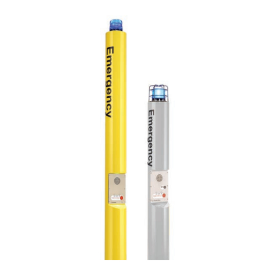
CB 5 Series for your Code Blue application. CB 5 Series Help Points are the original Code Blue pedestal units that set the industry ® CB 5 Series standard for rugged construction, full feature availability and high visibility. The easily recognized throughout a full 360-degree area. The high output strobe is easily identifiable by security when activated. - Page 6 CB 5 Series Administrator Guide This guide contains all of the CB 5 Series information. This guide contains a general overview of the CB 5 Series options and its applications, installation and wiring. CB 5-s with CB 5-s with CB 5-s...
-
Page 7: Getting Started
1. EIA/TIA, ANSI, CSA and BICSI cabling or similar standards shall be adhered to for proper operation of Code Blue communication devices connected to copper or fiber infrastructures. Communications cable and electrical cable in the same conduit is not an acceptable instal- lation and shall not be supported. - Page 8 CB 5 Series Administrator Guide CB 5-s, CB 5-p Tools Required 1. Ladder to reach the top of the units 2. Drill and security bit for removing and inserting security screws on phone, dome top and access door 3. 11/8 socket set and extension for installing anchor bolts or Deck Mount Kits 4.
-
Page 9: Spare Parts
CB 5 Series Administrator Guide 4 Spare Parts CB 5-s Part Part Number LED Strobe Light 40159 LED Faceplate Light 40196 Faceplate Screws 41544 (6pk) Access Door Screws 41545 (2pk) Manifold R/B 5-way 40101 Analog Surge Suppressor 41471 IP Surge Suppressor... - Page 10 Access Door Screws 41545 (2pk) Manifold R/B 5-way 40101 Analog Surge Suppressor 41471 IP Surge Suppressor 41421 CB 5 Series Additional Options Part Part Number Overhead Camera Mount Need Color for Part# Multi Tap Transformer 120V, 240V, 277V 40104 (powers accessories)
-
Page 11: Power Requirements
CB 5 Series Administrator Guide 5 Power Requirements (2020) (The following power requirements include the 5 Series and also ALL OTHER Code Blue units.) Component Specs Faceplates Voltage Max Current Max Watts Norm Current Norm Watts KWHrs High V IA4100 24V AC 0.40... - Page 12 0.22 S-1050 LED Strobe w/ Photocell 24V AC 2.80 67.20 0.22 5.28 0.13 12V DC 2.68 32.16 0.38 4.56 0.11 CB 5 Series 24V DC 2.68 64.32 0.38 9.12 0.22 LED Light Bar 24V AC 0.04 0.96 0.04 0.96 0.02 12V DC 0.04...
- Page 13 ® CB 4-u w/ NightCharge 0.22 120V AC 0.13 0.11 CB 5 Series 0.22 0.02 0.01 0.02 Administrator Guide 1.21 Power Requirements continued Models With IP5000 Faceplate Voltage Current Watts KWHrs CB 1-e 24V AC 0.33 7.92 0.19 12V DC 0.43...
-
Page 14: Legacy Power Requirements
CB 5 Series Administrator Guide 6 Legacy Power Requirements (The following power requirements include the 5 Series and also ALL OTHER Code Blue units.) Code Blue 259 Hedcor Street Holland, MI 49423 USA 800.205.7186 www.codeblue.com page 14 of 50 GU-158-M •... - Page 15 CB 5 Series Administrator Guide Code Blue 259 Hedcor Street Holland, MI 49423 USA 800.205.7186 www.codeblue.com page 15 of 50 GU-158-M • • • •...
-
Page 16: Software Configuration
A sophisticated emergency management platform for your blue light phone network, ToolVox offers unique real-time monitoring and provisioning options for emergency phones and public address speakers, effectively acting as a hub for connecting Help Points and other Code Blue devices. Us- ® ing our proprietary incident response software, Blue Alert MNS and EMS, you can send alerts via ®... -
Page 17: Cb 5-S Low Voltage Exploded View
CB 5 Series Administrator Guide 8 CB 5-s Low Voltage Exploded View BALL # PART # DESCRIPTION CALL Standard / Custom Graphic 40159 LED Beacon Strobe 40115 Complete LED Beacon Strobe Replacement Kit 41471 Analog Surge Suppressor 41421 IP Surge Suppressor... -
Page 18: Cb 5-S High Voltage Exploded View
CB 5 Series Administrator Guide 9 CB 5-s High Voltage Exploded View BALL # PART # DESCRIPTION CALL Standard Graphic CALL Custom Graphic 40159 LED Beacon Strobe 40115 Complete LED Beacon Strobe Replacement Kit 41471 Analog Surge Suppressor 41421 IP Surge Suppressor... -
Page 19: Cb 5-P Low Voltage Exploded View
CB 5 Series Administrator Guide 10 CB 5-p Low Voltage Exploded View BALL # PART # DESCRIPTION CALL Standard / Custom Graphic 40159 LED Beacon Strobe 40115 Complete LED Beacon Strobe Replacement Kit 44022 Strobe Guard 41471 Analog Surge Suppressor... -
Page 20: Cb 5-P High Voltage Exploded View
CB 5 Series Administrator Guide 11 CB 5-p High Voltage Exploded View BALL # PART # DESCRIPTION CALL Standard Graphic CALL Custom Graphic 40159 LED Beacon Strobe 40115 Complete LED Beacon Strobe Replacement Kit 44022 Strobe Guard 41471 Analog Surge Suppressor... -
Page 21: Cb 5-S With Decorative Top Low Voltage Exploded View
CB 5 Series Administrator Guide 12 CB 5-s with Decorative Top Low Voltage Exploded View BALL # PART # DESCRIPTION CALL Standard / Custom Graphic 40002 Decorative Top Assembly 41471 Analog Surge Suppressor 41421 IP Surge Suppressor 41700 24V Fuse Block... -
Page 22: Cb 5-S With Decorative Top High Voltage Exploded View
CB 5 Series Administrator Guide 13 CB 5-s with Decorative Top High Voltage Exploded View BALL # PART # DESCRIPTION CALL Standard Graphic CALL Custom Graphic 40002 Decorative Top Assembly 40100 Power Brick 120V, 240V, 277v, 347V 41545 Access Door Security Screws (2 pk) 50001 Single Button IA4100 Analog Phone –... -
Page 23: How To Replace Led Light Connectors
Administrator Guide 14 How to Replace LED Light Connectors As of 2020, Code Blue strobe, area and faceplate lights come with Wago connectors. These con- nectors provide ease of use and a much stronger connection. Below are the steps needed to change to the new connectors. - Page 24 CB 5 Series Administrator Guide Strip all wires and twist tight. Place small screwdriver into square hole and push down. Insert cut wire into round hole and remove screwdriver. Repeat on the rest of the connectors. Once all connectors have been switched, you are ready to apply power to the LED.
-
Page 25: Cb 5-S And Cb 5-P Installation Instructions
2½ inches above the concrete at an even height. To accom- plish this, use a small level and check all three directions. These nuts are not adjustable after the unit is in place. The bottom edge of the Code Blue unit will be ½-inch above the concrete when installed. - Page 26 CB 5 Series Administrator Guide Figure 1 Figure 2 All wiring must be installed and connected by experienced and certified personnel to meet local and national electrical codes, and will include a service disconnect. Code Blue 259 Hedcor Street Holland, MI 49423 USA 800.205.7186...
-
Page 27: Cb 5 Series Tower Base Gasket Installation Instructions
2.2 Set the Code Blue unit on the anchor bolts. Align the phone plate in the desired direction and lift the Code Blue unit over the anchor bolts. Note that the unit weighs approximately 180-230 pounds and that the 5 Series does not contain a bracket on the inside of the unit. - Page 28 CB 5 Series Administrator Guide 3.0 INSTALL THE BASE GASKET 3.1 Access the mounting studs through the access door on the side of the unit. 3.2 Set the gasket on the bolts and cut a small hole where the conduit is located.
-
Page 29: Cb 5-S With Public Address Installation Instructions
Gasket 3.1 After all of the connections are made, mount the PAS unit onto the PAS Adapter Ring. Rotate to align the Code Blue CB 5 Pedestal six holes and secure with the provided six #10-24 countersunk security screws. 4.0 SEE GUIDE FOR BEACON/STROBE INSTALL NOTE: 120V AC must be supplied to the unit. -
Page 30: Cb 5-S With Decorative Top Installation Instructions
2½ inches above the concrete at an even height. To accom- plish this, use a small level and check all three directions. These nuts are not adjustable after the unit is in place. The bottom edge of the Code Blue unit will be ½-inch above the concrete when installed. - Page 31 CB 5 Series Administrator Guide Figure 1 Figure 2 All wiring must be installed and connected by experienced and certified personnel to meet local and national electrical codes, and will include a service disconnect. Code Blue 259 Hedcor Street Holland, MI 49423 USA 800.205.7186...
-
Page 32: Cb 5 Series Anchor Bolt Installation Instructions
1.3 Set the Anchor Bolts in the Wet Foundation – Three 24-inch L-shaped anchor bolts and an aligning template are supplied for anchoring the Code Blue unit. The bolts should be set into the foundation so that six inches are left showing above the finished grade level. The anchor bolts should be aligned, using the supplied template, so the phone faceplate on the unit will face in the desired direction. -
Page 33: Cb 5 Overhead Camera Mount Installation Instructions
CB 5 Series Administrator Guide 20 CB 5 Overhead Camera Mount Installation Instructions TOOLS REQUIRED Ladder Access Panel 3/8Wrench Security Bit INSTALLING THE OVERHEAD CAMERA MOUNT The camera mount will come with a gasket already mounted to the bracket on the arm. Place the bracket over the mounting holes and insert the four 3/8-16 X 1 stainless bolts. - Page 34 CB 5 Series Administrator Guide CB 5-S W/PAS AND OVERHEAD CAMERA MOUNT Please contact Customer Service with any questions or concerns. Email: customerservice@codeblue.com Phone: 616-392-8296, Opt. 2 Code Blue 259 Hedcor Street Holland, MI 49423 USA 800.205.7186 www.codeblue.com page 34 of 50 GU-158-M •...
-
Page 35: 1000/S-1050 Installation Instructions
CB 5 Series Administrator Guide 21 S-1000 & S-1050 Installation Instructions NOTE: Instructions pertain to Model S-1000 LED Beacon/Strobe and Model S-1050 LED Beacon/Strobe only POSITIVE (12-24V DC or AC) BLACK COMMON (GROUND) YELLOW (FLASH MODE) DRY CONTACT CLOSED = "ON"... - Page 36 CB 5 Series Administrator Guide PROGRAMMING PRIMARY & SECONDARY MODES 1. Remove power from unit. 2. Short the Yellow wires together. 3. Restore power to the unit and wait until the unit begins to flash. Once the unit begins to flash, remove the short.
-
Page 37: Poe Installation Instructions
CB 5 Series Administrator Guide 22 PoE Installation Instructions PoE extractor. Code Blue 259 Hedcor Street Holland, MI 49423 USA 800.205.7186 www.codeblue.com page 37 of 50 GU-158-M • • • •... -
Page 38: Cb 5 Series Deck Mount Installation Instructions
CB 5 Series Administrator Guide 23 CB 5 Series Deck Mount Installation Instructions 1.0 DECK MOUNT FOUNDATION 1.1 Drill Deck Holes – Drill three holes through the deck or floor for the three 3/4” threaded rods. The holes should be aligned, using the template provided, so the phone faceplate on the unit will face in the desired direction (see figure below). -
Page 39: (Prior To 2015)
CB 5 Series Administrator Guide 24 CB 5-s & CB 5-p 24V or 120V Multi-Tap Power Brick Wiring (prior to 2015) Product wiring diagram shown reasonably represents current offering and is intended to assist in component identifi cation and service. Earlier product production may have different components and wiring connections. -
Page 40: (After 2015) (With 24V Fuse Block)
CB 5 Series Administrator Guide 25 CB 5-s and CB 5-p 24V Standard Wiring (after 2015) (with Fuse Block) Lighting Units IA4100 LED Area Light Beacon Strobe 24 Volts AC / DC or 12 – 24 Volts AC or DC... - Page 41 CB 5 Series Administrator Guide 26 CB 5-s and CB 5-p 120V Standard Wiring (prior to 03/2013) (with Hammond Transformer) (with Hammond Transformer) Product wiring diagram shown reasonably represents current offering and is intended to assist in component identifi cation and service. Earlier product production may have different components and wiring connections.
-
Page 42: (After 2015) (With Triad Transformer)
CB 5 Series Administrator Guide 27 CB 5 Series 120V Standard Wiring (after 2015) (with Triad Transformer) Lighting Units Beacon Strobe 12 – 24 Volts AC or DC IA4100 LED Faceplate light 12 – 24 Volts AC or DC Output... -
Page 43: Cb 5 Series With Public Address Wiring
CB 5 Series Administrator Guide 28 CB 5 Series with Public Address Wiring Code Blue 259 Hedcor Street Holland, MI 49423 USA 800.205.7186 www.codeblue.com page 43 of 50 GU-158-M • • • •... - Page 44 CB 5 Series Administrator Guide Code Blue 259 Hedcor Street Holland, MI 49423 USA 800.205.7186 www.codeblue.com page 44 of 50 GU-158-M • • • •...
-
Page 45: Multi-Tap Transformer Wiring
CB 5 Series Administrator Guide 29 Multi-Tap Transformer Wiring Side of the Incoming Power from Primary Side of the Secondar Supplier Transformer Transformer Neutral Source L1 (White) Primary Volt Amps 250 Secondar olt Amps 160 ETL – UL ______________ Source L2 (Black) -
Page 46: Maintenance Schedule
CB 5 Series Administrator Guide 30 Maintenance Schedule LEGEND Guard tasks Technician tasks DAILY OR WEEKLY Perform functional communications check Action: Press red button Strobe activates Red LED “Call Placed” light turns on Message plays Call connects, green LED “Call Received” light turns on ... - Page 47 Administrator Guide UNIT SURFACE MAINTENANCE The painted and stainless steel Code Blue models require periodic care to sustain their aesthetic appearance. Units located outdoors are vulnerable to harsh environmental conditions, including UV rays, acid rain, diesel fumes and airborn iron particles (i.e., dust) which over time may cause unit discoloring.
-
Page 48: Locating Unit Serial Numbers
CB 5 Series Administrator Guide 31 Locating Unit Serial Numbers Remove the access plate cover with the special security bit. The serial number will be listed on the manufacturer’s label located on the backside of the access plate cover (1). - Page 49 Administrator Guide 32 Warranty Code Blue Corporation provides a limited warranty on this product. Refer to your sales agreement to establish the terms. In addition, Code Blue’s standard warranty language, as well as information regarding support for this product while under warranty, is available at www.codeblue.com/support.
- Page 50 CB 5 Series Administrator Guide Download Information 33 Download Information Code Blue now has a centralized location where you can find installation, setup, information, configuration and operation instructions. ® 1. Centry Administrator Guide: www.codeblue.com/resources/guides 2. CB 1 Series Administrator Guide: www.codeblue.com/resources/guides...
Need help?
Do you have a question about the CB 5 Series and is the answer not in the manual?
Questions and answers