Advertisement
Quick Links
Version #1.0
September 28, 2023
Stock Code:
CB128-SLIDER-CEDAR-BEV
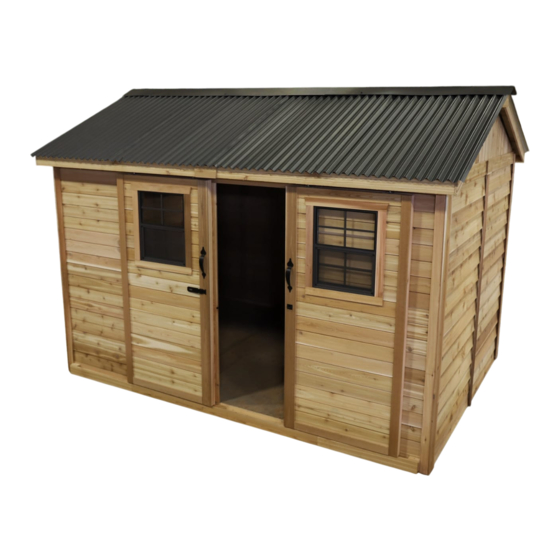
Thank you for purchasing a
12x8 Cabana. Please take
the time to identify all the
parts prior to assembly.
Important Information:
- It is the sole responsibility of the customer to check with your local municipal or county by-laws before
ordering this product to confirm it complies with building codes in your area.
- If the product is elevated, any structural and building code requirements are solely the customer's
responsibility, and should be abided by.
- Snow load ratings vary by geographical location. If heavy or wet snowfall occurs, it is advisable to sweep
snow off roof frequently.
- In areas with high or gusty wind conditions, it is advisable to install the structure securely to the ground.
- Have a regular maintenance plan to ensure screws, doors, windows and parts are tightly affixed.
- All structures purchased from Outdoor Living Today are covered for a period of one year for defects in
manufacturing and workmanship. Costs incurred for customer installations are not included.
- Failure to use supplied parts included in this kit could result in poor product performance and may void
your warranty. Please contact Outdoor Living Today's Customer Toll Free Line if you plan to deviate from
our written instructions.
Customer agrees to hold Outdoor Living Today and any Authorized Dealers free of any liability for improper
installation, maintenance and repair.
In the event of a missing or broken piece, simply call the Outdoor Living Today Customer Support Line
@ 1-888-658-1658 within 30 days of the delivery of your purchase. It is our commitment to you to courier
replacement parts, free of charge, within 10 business days of this notification. Replacement parts will not be
provided free of charge after the 30 day grace period.
Outdoor Living Today
12x8 CABANA SLIDER
WITH BEV SIDING & CEDAR
ROOF
www.outdoorlivingtoday.com
Page 1
sales@outdoorlivingtoday.com
Advertisement

Related Manuals for OLT CABANA CB128-SLIDER-CEDAR-BEV


Summary of Contents for OLT CABANA CB128-SLIDER-CEDAR-BEV
- Page 1 12x8 CABANA SLIDER WITH BEV SIDING & CEDAR ROOF Version #1.0 September 28, 2023 Stock Code: CB128-SLIDER-CEDAR-BEV Thank you for purchasing a 12x8 Cabana. Please take the time to identify all the parts prior to assembly. Important Information: - It is the sole responsibility of the customer to check with your local municipal or county by-laws before ordering this product to confirm it complies with building codes in your area.
- Page 2 What to do before my Shed arrives? • Become familiar with this assembly manual and determine if you can com plete the project yourself or will require a professional contractor. • One helper is recommended to assist in constructing your chalet. It generally takes two people more than two days to assemble a chalet.
- Page 3 Foundation Types for 8x12 Garden Shed 96” 96” 136 1/2” 136 1/2” Completed Foundation Concrete Foundation Floor Frame Concrete Slab Foundation: - Slab must be at least the same size as assembled floor frame (136 1/2” x 96”) or larger. - 6”...
- Page 4 Thank you for purchasing our 12x8 Cabana. Please take the time to identify all the parts prior to assembly. Parts List Steps D. Trim / Misc. Section Steps 48 - 52 Filler & Outer Trim A. Floor Section 7 - Bottom Skirting Side & Rear (Bevel) - 1/2”...
- Page 5 12x8 CABANA - CEDAR ROOF Hardware Kit (Provided) 18 pcs 3” 30 pcs 3/4” Black Headed Screw 2 1/2” 350 pcs 320 pcs 1 1/2” Finishing 2” 150 pcs 1 1/2” 60 Pcs 1 1/4” Shingle 1 pc 26 pcs 3/4” Square Drive Bit Silver Single...
- Page 6 Regular Maintenance & Tips to prolong the life of your shed. Before/During Assembly: 1.) Paint each face and edge of your plywood floor with a latex exterior paint. 2.) Caulk wall seams if gaps appear. 3.) Caulk around window framing. 4.) Caulk perimeter between floor plywood and bottom wall plate.
- Page 7 A. Floor Section Exploded view of all parts necessary to complete Floor Section. Identify all parts prior to starting. Note: Floor Footprint is 136 1/2” wide x 96” deep. Plywood Floor Plywood Floor Large (3) Small (3) Floor Joist Frames Small (3) Floor Runners (8) Floor Joist...
- Page 8 When correctly positioned, attach each Joist with 4 - 2 1/2” screws (2 per end). You can find the Square Drive Screw Bit in the Hardware Kit Bag. You can find the Square Drive Bit for the screws in with the Hardware Kit Bag. Attach each Large and Small Floor Joist Lay out Floor Joist Frames as illustrated.
- Page 9 Parts Attach Front Floor Runners to completed floor frame with notch Front Floor Runners aligned flush with corner of floor framing and edge overhanging front (1 1/2” x 5 1/2” x 68 3/16”) x 2 by 2”. The overhanging edge of the Front Floor Runners will be used Hardware later to support the sliding door track.
- Page 10 push plywood Important - Make sure floor is together at seams. level before moving on to wall section. Use a level to confirm, and shim floor joists as required. Position all Large and Small Plywood Floor pieces on top of completed Floor Joists. Plywood will sit flush with outside of Floor Joist Frame.
- Page 11 B. Wall Section Exploded view of all parts necessary to complete the Wall Section. Identify all parts prior to starting. Front/Rear Top Plates (4) Gable Walls (4) Side Top Plates (6) Door Headers (3) Solid Wall Panels (7) Front Wall Panel (2) Interior Door Header (1) Important: Pilot hole ALL 2x3 Wall...
- Page 12 Lay out all the Wall Panels and become familiar with their location. On Standard Kits, there are 7 Solid Wall Panels and 2 Front Wall Panels. Make sure to position panels right side up so water is directed away from and not into shed. Look at door opening and exposed wide Floor Runner to determine proper wall position to confirm.
- Page 13 Do Not Attach Walls To Floor Until Step 22 Hardware (Steps 15 -17) Position Side Solid Wall Panel into place on Plywood Floor. Butt both 2 1/2” Screws vertical wall studs of side and rear walls together and attach with 3 - 2 1/2” x 18 total Screws.
- Page 14 Pilot Hole first. Pilot Hole first. Pilot Hole first. Complete all Side and Rear Wall attachments as per Steps 15 - 16. The rear wall is made up of three Rear Solid Wall Panels. Outdoor Living Today www.outdoorlivingtoday.com sales@outdoorlivingtoday.com Page 14...
- Page 15 Pilot Hole first. Pilot Hole first. Parts Hardware Position and attach both Front Wall Panels Front Wall Panels 2 1/2” Screws as per Steps 15 - 17. (35” x 73”) x 2 x 6 total Step to front and top. Align flush outside with wall siding.
- Page 16 Aluminum strip on back of Long Door Header Attach Door Header - Short to other side. Position and attach Door Header - Long between Short Door Headers. The Long Door Header has an aluminum strip attached to the back for added support.
- Page 17 Advice: Prior to fastening walls and installing rafters, take time to confirm your walls are level, square and plumb. Measure diagonal at top and bottom of walls corner-to-corner. This should be approximately 159 7/8”. More importantly, if measurements are not within 1/4”, your walls are not square. Adjusting now will make it easier to install roof section Pilot Hole first.
- Page 18 Next, attach the Front Top Plates. The Front and Rear Top Plates are angle cut down the length. Once again, position Top Plates on wall frame so they are flush. Front and Rear Top Plates will fit between Side Top Plates. Attach with 4 - 2” Screws per plate. Complete all other Side & Rear Top Plate attachments the same.
- Page 19 Flashing overhangs wall on outside. Use a straight edge to check that angle of Gable lines up with Top Wall Plate angle. Adjust Gable for best fit. Place completed Gable section so framing sits flush with the inside of the Top Wall Plate. It should also be centered side-to-side on the Top Wall Plate.
- Page 20 C. Rafter & Roof Section Exploded view of all parts necessary to complete the Rafter and Roof Section. Identify all parts prior to starting. Filler Shingles (20) Middle Roof Panels (2) Outside Roof Panels (2) Outside Roof Panels (2) Metal Ridge Board Ridge Boards (4) Connectors (2) 52 1/2”...
- Page 21 Ridge Board 2 1/2” Screws into Doubled Important: up Rafters Pilot Hole Ridge Board to prevent splitting! Soffits Locate 9 - Rafters, 2 - Soffits & completed Ridge Board. Lay out on level ground as shown to the right. Double up Rafters as illustrated. Screw doubled up Rafters together with 3 - 2 1/2” Screws per piece.
- Page 22 Soffit Carefully lift 1 completed Rafter Section up (make sure Soffit is facing down) and place on gable framing. Soffit should sit approx. 1/8” away from wall panel. End Rafter will sit Gable Notch flush with end of wall. Slide Rafter Section up on gable framing until bottom of Ridge Board slips into gable notch. Soffit will sit approximately 1/8”...
- Page 23 Offset Metal Ridge Board Connectors Hardware At the peak, align Ridge Boards so they are flush together and secure 1 1/4” Screws them with 12 - 1 1/4” Screws. To completely secure Ridge Boards, place x 12 total 4 - 3/4” Screws into any of the remaining Metal Ridge Board Connector 3/4”...
- Page 24 91” across Parts Roof Gussets are positioned on middle Rafters. Prior to attaching, Roof Gussets make sure walls are properly aligned. Have two helpers push walls at the (3/4” x 3 1/2” x 72”) x 3 top from the outside of shed until inside to inside measurement between Hardware front and rear plates is 91”.
- Page 25 Roof Plywood recessed 1/8” from Rafter end. Angle Screw from Rafter into Plywood with 2 1/2” Screw. 2 1/2” Screw in Bottom Row of Shingles. Place Outside Roof Panel so it sits flush on 3rd Rafter from the outside (doubled up Rafter). Plywood on Roof should be flush with end of Rafter at bottom, and with seam of doubled up Rafters.
- Page 26 Shingles overhang Plywood on Outside Roof Panel. Lift up, position and attach 2nd Outside Roof Panel on Rafters as per Step 40. Outside Panel Position and attach remaining Roof Panels as per Steps 39 - 41. Roof Filler Shingles are included to cover Roof seams. Starting at the bottom, slide the first Long Shingle in until flush with other bottom Shingles.
- Page 27 Attach above the exposure line. Exposure Line Slide in another Filler Shingle and attach as per Step 44. On your last row of Shingles, attach smaller Filler Shingles with 2 - 1 1/2” Shingle Screw first Filler Shingle down to Rafters Nails near the top, to be covered by Ridge Caps using 2 - 2 1/2”...
- Page 28 D. Miscellaneous Section Exploded view of all parts necessary to complete the Skirting, Trim, Fascia and Miscellaneous Pieces. Identify all parts prior to starting. Expert Advice: When installing trim, sort pieces according to color and pieces that are most pleasing to the eye. Start with least visible side of shed and use the least desirable pieces first. Install trim to most visible side of shed as your skill installing trim improves.
- Page 29 Parts Attach Bottom Skirting pieces around the Bottom Skirting Side & Rear (Bevel) base of the shed. Skirting will hide floor framing. (1/2” x 4 1/2” x 45 1/4”) x 7 Gaps on side will be covered by Wide Trim pieces Bottom Skirting Front later.
- Page 30 Flush to bottom of wall siding. Parts Hardware Attach Filler Trim to each corner side Filler Trim 1 1/2” Finishing Nails wall. Align Filler Trim so it sits flush with the (3/4” x 2 1/2” x 75”) x 4 x 32 total bottom of the last piece of Wall siding.
- Page 31 Trim out Rear Solid Walls by attaching Top Wall Trim. Position with thick end of Bevel downward at top of wall, tight against Soffits. Attach with 4 - 1 1/2” Finishing Nails per piece. Parts Hardware Top Wall Trim (Bevel) 1 1/2”...
- Page 32 Twist Roller Cart onto bolt. After doors are hung, you may need to adjust this until doors hang straight up and down at equal height. Locate all four Roller Assemblies. Before attaching to top of doors, assemble the units as shown above.
- Page 33 1/4” Gap Lower Door Track 1 5/8” Locate Door Tracks and Door Stops. Middle Door Stop should be centered on shed and outer Door Stops should be 1 1/2” from edge of bottom skirting. Door Tracks rest on Long Floor Runners.
- Page 34 Door Stop and Track Cover are flush Locate Door Track Covers. Lineup so Track Covers are flush with Door Stops. This creates an enclosure so doors can not slide out of the track. Secure each piece of Track Cover with 4 - 2 1/2”...
- Page 35 Right Side Door Left Side Door Left Side Door Door Flange attaches to Left Side Door. Position Interior Door Flange on the rear of the left side door (when viewed from the front of the shed). Ensure Flange is flush with the inside of the door frame and attach with 5 - 1 1/4” Screws.
- Page 36 Fit Corner Trim tight underneath Soffit. Wide Corner Trim Align bottoms of both corner trim pieces flush. To trim out corners, start with a Corner Trim, align tight underneath Soffit and Rafter. Align Wide Corner Trim with bottom of Corner Trim. Corner Trim will cap the Wide Corner Trim. Do a dry run in each corner before attaching to confirm positioning.
- Page 37 Attach Rear Wall Narrow Trim where wall panels come together and leave a seam. Position trim equally on wall seam and tight underneath Soffit and Rafter. Use 8 - 1 1/2” Finishing Nails per piece to secure. Parts Hardware Rear Wall Narrow Trim 1 1/2”...
- Page 38 Attach Facia/Roof Nailing Strips (3/4” x 2 1/2” x 51”) to the underside edge of Roof Plywood with 4 - 1 1/4” Screws per piece. Nailing Strip will make it easier to attach Side Facia in Step 63. Complete attaching strips on left and right sides (2 per side, 4 pieces total). Parts Hardware Facia Nailing Strips...
- Page 39 Pentagon Facia Plate Attach Pentagon Facia Plate where End Facia meets at the peak. Use 4 - 1 1/2” finishing nails per piece to secure. Parts Hardware 1 1/2” Finishing Nails Pentagon Facia Plates x 8 total (1/2” x 3 1/2” x 8”) x 2 Facia Detail Plate Horizontal Gable Detail Plate Attach Facia Detail Plate to side facia where they meet in the middle.
- Page 40 Alternate Ride Cap seams (offsetting angle cut at peak) Thin End Important: Butt (thick) end of Ridge Cap will be facing towards the outside of shed. Place 1st Roof Ridge Cap on roof peak overhanging shingles by approximately 1”. Attach with 2 - 1 1/2”...
- Page 41 Trim dado sits in flange. Position Window Trim around window doing a dry run first and attach with 4 - 1 1/2” Finishing Nails per piece. Window trim has a small dado on reverse face. Outside flange of window will roughly sit in the dado to give a better fit. Complete both windows the same. Parts Hardware Window Trim Kit x 2...
- Page 42 Note: Our Sheds are shipped as an unfinished product. If exposed to the elements, the lumber will weather to a silvery-gray color. If you prefer to keep the lumber looking closer to the original color, we suggest that you treat the wood with a good oil base wood stain.
Need help?
Do you have a question about the CABANA CB128-SLIDER-CEDAR-BEV and is the answer not in the manual?
Questions and answers