Advertisement
Quick Links
Version #2.2
July 19, 2021
Stock Code #
CB128-FJ-METAL
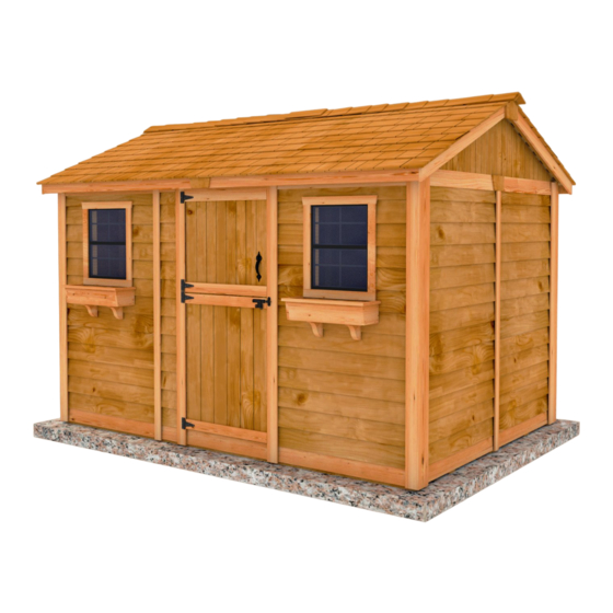
Thank you for purchasing
a 12x8 Cabana. Please take
the time to identify all the
parts prior to assembly.
Safety Points and Other Considerations
Our products are built for use based on
proper installation on level ground and
normal residential use. Please follow the
instruction manual when building your
shed and retain the manual for future
maintenance purposes.
Customers are responsible for ensuring
a solid, level, well-draining site for
construction.
Please check with your local municipal
or county by-laws before ordering this
product to confirm it complies with
building codes.
In the event of a missing or broken piece, call the Outdoor Living Today Customer Support Line @ 1-888-658-1658 with-
in 30 days of the delivery of your purchase. It is our commitment to you to courier replacement parts, free of charge,
within 10 business days of this notification. Replacement parts will not be provided free of charge after the 30 day
grace period.
All structures purchased from Outdoor Living Today are covered for a period of one year for defects in manufacturing
and workmanship. Costs incurred for customer installations are not included.
Failure to use supplied parts included in this kit could result in poor product performance and may void your warranty.
Please contact Outdoor Living Today's Customer Toll Free Line if you plan to deviate from our written instructions.
Toll Free 1-888-658-1658
12x8 Cabana Shed
FJ Bevel Model with Metal Roof
Assembly Manual
- Snow load ratings vary by geographical location. If heavy or wet snowfall occurs, it
is advisable to sweep snow off roof frequently.
- If the product is elevated, any structural and building code requirements are solely
the customer's responsibility, and should be abided by.
- In areas with high or gusty wind conditions, it is advisable to install the structure
securely to the ground.
- Have a regular maintenance plan to ensure screws, doors, windows and parts are
tightly affixed.
Customer agrees to hold Outdoor Living Today and any Authorized
Dealers free of any liability for improper installation, maintenance and
repair.
www.outdoorlivingtoday.com
Page 1
sales@outdoorlivingtoday.com
Advertisement

Subscribe to Our Youtube Channel
Related Manuals for OLT Cabana Shed CB128-FJ-METAL


Summary of Contents for OLT Cabana Shed CB128-FJ-METAL
- Page 1 12x8 Cabana Shed FJ Bevel Model with Metal Roof Assembly Manual Version #2.2 July 19, 2021 Stock Code # CB128-FJ-METAL Thank you for purchasing a 12x8 Cabana. Please take the time to identify all the parts prior to assembly. Safety Points and Other Considerations Our products are built for use based on proper installation on level ground and normal residential use.
- Page 2 What to do before my Shed arrives? • Become familiar with this assembly manual and determine if you can complete the project yourself or will require a professional contractor. • One helper is recommended to assist in constructing your shed. It generally takes two people over two days to assemble a shed.
- Page 3 Foundation Types for 8x12 Garden Shed 96” 96” 136 1/2” 136 1/2” Completed Foundation Concrete Foundation Floor Frame Concrete Slab Foundation: - Slab must be at least the same size as assembled floor frame (136 1/2” x 96”) or larger. - 6”...
- Page 4 Thank you for purchasing our 12x8 Cabana Garden Shed. Please take the time to identify all the parts prior to assembly. 1. Floor Section Parts List - Pages 2 and 3 Steps Floors 1-12 3 - 45 1/2” x 75” - Floor Joist Frames - Large 3 - 45 1/2”...
-
Page 5: Hardware Kit
Parts List - Pages 2 and 3 Steps Door Section 68-75 2 - 1/2” x 3 1/2” x 79” - Vertical Door Trim 1 - 1/2” x 2 1/2” x 79” - Front Wall Narrow Trim 1 - 1/2” x 1 1/4” x 32” - Horizontal Door Trim 1 - 1/2”... - Page 6 Regular Maintenance & Tips to prolong the life of your shed. Before/During Assembly: 1.) Paint each face and edge of your plywood floor with a latex exterior paint. 2.) Caulk wall seams if gaps appear. 3.) Caulk around window framing. 4.) Caulk perimeter between floor plywood and bottom wall plate.
-
Page 7: Floor Section
Exploded view of all parts necessary to complete A. Floor Section Floor Section. Identify all parts prior to starting. Note: Floor Footprint is 136 1/2” wide x 96” deep. Plywood Floor Large (3) Plywood Floor Small (3) Floor Joist Frames Small (3) Floor Runners (10) Floor Joist... - Page 8 When correctly positioned, attach each Joist with 4 - 2 1/2” screws (2 per end). You can find the Square Drive Screw Bit in the Hardware Kit Bag. find Square Drive Bit for the screws in with the Hardware Kit Bag. Attach each large and small floor joist Lay out Floor Joist Frames as illustrated.
- Page 9 Attach Floor Runners to completed floor frame. Make sure Runners are flush with There are 2 Floor Runners per 136 1/2” side and outside and front and rear floor framing 5 completed Runners in total. Use 6 - 2 1/2” Screws but not overhanging.
- Page 10 push plywood Important - Make sure floor is together at seams. level before moving on to wall section. Use a level to confirm, Hint: Use a chalk line and shim floor joists as required. to mark location of floor joists determine Position all Large &...
- Page 11 B. Wall Section Exploded view of all parts necessary to complete the Wall Section. Gable Walls (4) Identify all parts prior to starting. Front and Rear Top Plates (4) Side Top Plates (6) (Angle cut on edge) (4 Angle cut on one end and 2 square cut.) Window Wall Panel (2)
- Page 12 Important: Pilot hole ALL 2x3 Wall Studs with 1/8” drill bit prior Pilot Hole to screwing. This will make it first. much easier to attach together. Bottom Wall Plate Parts Hardware For each Solid Wall Panel, carefully lay panel Solid Wall Panels S1 - 2 1/2”...
- Page 13 Optional - Caulking seams will help prevent moisture from entering your shed. Caulking not included in kit. Do Not Attach Walls To Floor Until Step 23 Hardware (Steps 16 -18) Position side solid wall into place on plywood floor. Butt both vertical S1 - 2 1/2”...
- Page 14 Pilot Hole first. Pilot Hole first. Pilot Hole first. Complete all Side and Rear Wall attachments as per Steps 15 - 17. Toll Free 1-888-658-1658 www.outdoorlivingtoday.com sales@outdoorlivingtoday.com Page 14...
- Page 15 Pilot Hole first. Pilot Hole first. Parts Hardware Position and attach both Window Walls as Window Walls S1 - 2 1/2” Screws per Steps 15 - 18. (45 1/2” x 75”) x 2 x 6 total Pilot Hole first. Parts Hardware Position and attach Narrow Wall as per Narrow Wall...
- Page 16 Flush to tip of Bevel. Attach Vertical Door Jamb to Window Wall stud in door opening with 4 - 2 1/2” Screws. Position so Jamb is flush with tip of bevel siding on front Window Walls. Parts Hardware Flush with Window Vertical Door Jamb S1 - 2 1/2”...
- Page 17 Advice: Prior to fastening walls and installing rafters, take time to confirm your walls are level, square and plumb. Measure diagonal at top and bottom of walls corner-to-corner. This should be approximately 159 7/8”. More importantly, if measurements are not within 1/4”, your walls are not square. Adjusting now will make it easier to install roof section Pilot Hole first.
- Page 18 Next, attach the Front Top Plates. The Front and Rear Top Plates are angle cut down the length. Once again, position Top Plates on wall frame so they are flush. Front and Rear Top Plates will fit between Side Top Plates. Attach with 4 - 2” Screws per plate.
- Page 19 Flashing overhangs wall on outside. Use a straight edge to check that angle of Gable lines up with Top Wall Plate angle. Adjust Gable for best fit. Place completed Gable section so framing sits flush with the inside of the Top Wall Plate. It should also be centered side-to-side on the Top Wall Plate.
- Page 20 C. & D. Rafter and Roof Section Exploded view of all parts necessary to complete the Roof Section. Identify all parts prior to starting. Metal Ridge Metal Roof Caps (3) Foam Enclosures Panels (8) (Several Pcs) Batten Spacers (12) Roof Batten Ridge Boards Inside (8) (4) 2 - 84”...
- Page 21 Ridge Board Locate 9 - Rafters, 2 - Soffits & complet- 2 1/2” Screws ed Ridge Board. Lay out on level ground as into Doubled shown to the right. Double up Rafters as illus- up Rafters trated. Screw doubled up Rafters together with 3 - 2 1/2”...
- Page 22 Soffit Carefully lift 1 completed Rafter Section up (make sure Soffit is facing down) and place on gable framing. Soffit should sit approx. Gable Notch 1/8” away from wall panel. End Rafter will sit flush with end of wall. Slide Rafter Section up on gable framing until bottom of Ridge Board slips into gable notch. Soffit will sit approximately 1/8”...
- Page 23 Place second completed Rafter Section on Gable Walls as per Steps 32 - 33. Offset Metal Ridge Board Connectors Hardware (Step 35) At the peak, align Ridge Boards so they are flush together and secure S2 - 1 1/4” Screws them with 12 - 1 1/4”...
- Page 24 91” across Parts Roof Gussets are positioned on middle Rafters. Prior to attaching, make Roof Gussets sure walls are properly aligned. Have two helpers push walls at the top from the (3/4” x 3 1/2” x 72”) x 3 outside of shed until inside to inside measurement between front and rear plates Hardware is 91”.
- Page 25 Outside Inside Roof Outside Roof Batten Batten Roof Batten Flush to Ridge Board 3 3/4” Parts (Step 51 - 57) Locate 2 Outside Roof Battens and 1 Inside Roof Batten, Roof Battens Outside place on Roof Rafters. Place at top of Rafter section where Rafters (3/4”...
- Page 26 Locate 2 Outside Roof Battens and 1 Inside Roof Batten. Place outside Battens flush with Batten Spacers and overhanging outside Rafter by 3 3/4”. Secure row of Battens to Rafters with 9 - 1 1/4” screws (3 screws per Batten). Locate another pair of Batten Spacers and position flush with second row of Battens.
- Page 27 Repeat Steps 49 - 44 to complete Batten Section on opposite side of roof with remaining Battens and Batten Spacers. Parts (Step 46) Locate 4 Metal Roof Panels and 4 Metal Roof Hangars. To Metal Roof Panels temporarily hold the Metal Roof Panels in place, hook a Metal Roof (39”...
- Page 28 Approximatley 4” of overhang past Rafters. Overhang the Metal Roof Panels past the Battens on front and rear of shed by approxi- matley 1”. Adjust panels side-to-side to achieve desired width. Overall width past the Battens can vary from 1” - 3” depending on your preference. The overhang over the side of the shed will be set by the Metal Roof Hangars, but should be approximatley 4”...
- Page 29 Important: Remove Metal Roof Hangars Parts (Step 50) Before fully fastening Metal Roof Panels down, remove the Metal Foam Enclosures Roof Hangars and insert Foam Enclosures between Metal Roof (Several Pcs) Panels and Battens at the bottom of the roof. Enclosures will prevent moisture and unwanted bugs, etc from entering your shed through here.
- Page 30 Parts (Step 53) Locate remaining Foam Enclosures. Place Foam Enclosures at Foam Enclosures the top of roof panels. Foam Enclosures prevent moisture from coming (Several Pcs) in through the top of your shed. Parts (Step 54) Place 3 Metal Ridge Caps onto apex of roof. Evenly space from Metal Ridge Caps front to back of your shed, Metal Ridge Caps will overlap each other.
-
Page 31: Miscellaneous Section
D. Miscellaneous Section Important- Illustrations show shed with Cedar and Metal Roof Panels and assembly is interchangeable. Thicker at Butt Parts Attach Bottom Skirting - Bevel around the base of the shed. Bottom Skirting - Bevel Bevel is thicker at butt and thinner at top of board. Skirting will hide (1/2”... - Page 32 Flush to bottom of wall siding. Parts Hardware Attach Filler Trim to each corner side Filler Trim N1 - 1 1/2” Finishing Nails wall. Align Filler Trim so it sits flush with the (3/4” x 2 1/2” x 75”) x 4 x 32 total bottom of the last piece of Wall siding.
- Page 33 Fit Corner Trim tight underneath Soffit. Wide Corner Trim Corner Trim To trim out corners, start with a Corner Trim, align tight underneath Soffit and Rafter. Align Wide Corner Trim with bottom of Corner Trim. Corner Trim will cap the Wide Corner Trim. Do a dry run in each cor- ner before attaching to confirm positioning.
- Page 34 Trim out rear corners with remaining pieces of Corner Trim and Wide Corner Trim. Align and attach with 8 - 1 1/2” Finishing Nails per piece as per Step 58. Attach Horizontal Gable Trims to both sides of shed (2 per side). Position over gable and wall seam with thick end of Bevel downward.
- Page 35 Attach Rear Wall Narrow Trim where wall panels come together and leave a seam. Position trim equally on wall seam and tight underneath Soffit and Rafter. Use 8 - 1 1/2” Finishing Nails per piece to secure. Parts Rear Wall Narrow Trim (1/2”...
- Page 36 Facia/Roof Nailing Strips (4 @ 3/4” x 2 1/2” x 48” Parts Attach Facia/Roof Nailing Strips (3/4” x 2 1/2” x 51”) to Facia Nailing Strips the underside edge of roof battens with 4 - 1 1/4” Screws per (3/4” x 2 1/2” x 51”) x 4 piece.
- Page 37 Pentagon Facia Plate Parts Attach Pentagon Facia Plate where End Facia Pentagon Facia Plates meets at the peak. Use 4 - 1 1/2” finishing nails per (1/2” x 3 1/2” x 8”) x 2 piece to secure. Hardware N1 - 1 1/2” Finishing Nails x 8 total Facia Detail Plate Parts Attach Facia Detail Plate to side facia where they...
- Page 38 Vertical Door Trim flush with inside of Front Wall door opening. Narrow Trim Position Vertical Door Trim pieces flush with inside edge of Door opening and tight to Soffits on top. Position Front Wall Narrow Trim evenly on seam where Narrow Wall and Window Wall come together.
- Page 39 2“ Screws 3/4” screw Top and Bottom Hinges centered on door trim. Attach Door Hinges to Top and Bottom Dutch Door Middle Hinges sections. Top Door has trim overhanging door at bottom while bottom door has trim recessed slightly. Hinges should be centered on trims.
- Page 40 1/4” gap on inside. Slight gap.Top Trim overlaps bottom trim to prevent water from getting in. Place the Top Dutch Door Panel into place and gap top and bottom trims on the outside about 1/8” apart. On the inside, horizontal door frames should be about 1/4” apart. Use a shim once again to help you.
- Page 41 Temporarily position Interior Vertical Door Stop to help align Interior Barrel Bolt. Silver Barrel Bolt Hardware Attach Interior Silver Barrel Bolt to inside of door as illustrated Y5 - Silver Barrel Bolt above. Use 3/4” Silver Screws to secure. Refer to Step 75 to allow for x 1 total adequate clearance.
- Page 42 Window frame. Caulk gap. Screw insert into bottom (thick) part of siding. Parts To reduce possible water from penetrating Window Inserts x 2 into the window cavity, caulk gap on both sides of window opening prior to installing Window Hardware Insert.
- Page 43 Parts Assemble Flower Box with Assembly Instructions included on Page 44. Flower Box Kits x 2 Position completed Flower Box below bottom of window trim and secure with 2 - 2” Hardware Screws per box. Screw from inside of box into the center Window Wall stud. Attach S3 - 2”...
- Page 44 Outdoor Living Today Flower Box Assembly Instructions Exploded Side Trims (D) View Front Trim (C) End Caps (B) 1 1/4” Parts Lists: Nails (G) A - Base, Rear & Front Box Frames (3pcs) 3/4” x 5 1/2” x 23” B - End Cap Frames (2pcs) 3/4”...
- Page 45 Congratulations on assembling your 12x8 Cabana! Note: Our Sheds are shipped as unfinished products. If exposed to the elements, the western red cedar lumber will weather to a silvery-gray color. If you prefer to keep the cedar lumber looking closer to the original color, we suggest that you treat the wood with a good oil base wood stain. You may also wish to paint your new shed rather than stain it.
Need help?
Do you have a question about the Cabana Shed CB128-FJ-METAL and is the answer not in the manual?
Questions and answers