Advertisement
Quick Links
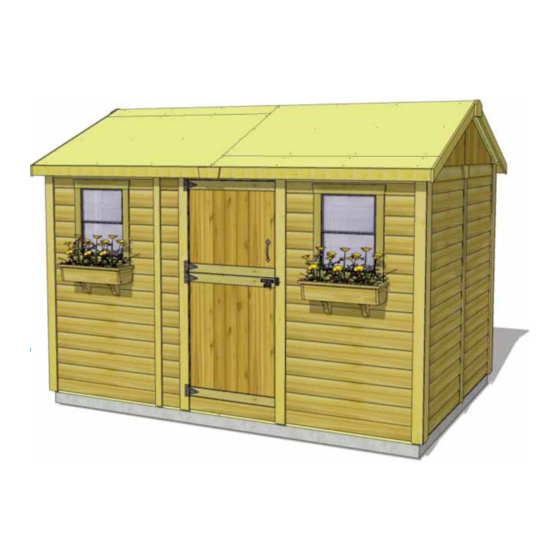
Thank you for purchasing
a 12x8 Cabana. Please take
the time to identify all the
parts prior to assembly.
Roof Area: 113 sqft
Safety Points and Other Considerations
Our products are built for use based on
proper installation on level ground and
normal residential use. Please follow the
instruction manual when building your
shed and retain the manual for future
maintenance purposes.
Customers are responsible for ensuring
a solid, level, well-draining site for
construction.
Please check with your local municipal
or county by-laws before ordering this
product to confirm it complies with
building codes.
In the event of a missing or broken piece, call the Outdoor Living Today Customer Support Line @ 1-888-658-1658 with-
in 30 days of the delivery of your purchase. It is our commitment to you to courier replacement parts, free of charge,
within 10 business days of this notification. Replacement parts will not be provided free of charge after the 30 day
grace period.
All structures purchased from Outdoor Living Today are covered for a period of one year for defects in manufacturing
and workmanship. Costs incurred for customer installations are not included.
Failure to use supplied parts included in this kit could result in poor product performance and may void your warranty.
Please contact Outdoor Living Today's Customer Toll Free Line if you plan to deviate from our written instructions.
1-888-658-1658
12x8 Cabana -
Plywood - Slider
Assembly Manual
- Snow load ratings vary by geographical location. If heavy or wet snowfall occurs, it
is advisable to sweep snow off roof frequently.
- If the product is elevated, any structural and building code requirements are solely
the customer's responsibility, and should be abided by.
- In areas with high or gusty wind conditions, it is advisable to install the structure
securely to the ground.
- Have a regular maintenance plan to ensure screws, doors, windows and parts are
tightly affixed.
Customer agrees to hold Outdoor Living Today and any Authorized
Dealers free of any liability for improper installation, maintenance and
repair.
www.outdoorlivingtoday.com
Page 1
Version #1.0
June 22, 2020
sales@outdoorlivingtoday.com
Advertisement

Related Manuals for OLT 12x8 Cabana


Summary of Contents for OLT 12x8 Cabana
- Page 1 Version #1.0 June 22, 2020 Plywood - Slider Assembly Manual Thank you for purchasing a 12x8 Cabana. Please take the time to identify all the parts prior to assembly. Roof Area: 113 sqft Safety Points and Other Considerations Our products are built for use based on proper installation on level ground and normal residential use.
- Page 2 Thank you for purchasing our 12x8 Cabana Garden Shed. Please take the time to identify all the parts prior to assembly. 1. Floor Section Parts List - Page 2 Steps Floors 3 - 45 1/2” x 75” - Floor Joist Frames - Large 1-13 3 - 45 1/2”...
- Page 3 12 x 8 CABANA HARDWARE SHEET Hardware Kit (Provided) S2 - 1 1/4” 325 Pcs 26 Pcs S4 - 3” SS2 - 3/4” 16 Pcs Silver S1 - 2 1/2” 280 Pcs 16 Pcs SB1 - 3/4” Black Headed N1 - 1 1/2” S3 - 2”...
- Page 4 What Can I Do Before My Shed Arrives? Before starting your project become familiar with this assembly manual and determine if you can complete the project yourself or will require a professional contractor. Please note that certain counties and municipalities require building permits prior to installation. We recommend to all consumers that they check with their local county/municipality for these specifics prior to purchasing any of our products since this is your sole responsibility.
- Page 5 Exploded view of all parts necessary to complete A. Floor Section Floor Section. Identify all parts prior to starting. Note: Floor Footprint is 136 1/2” wide x 96” deep. Plywood Floor Plywood Floor Center Floor Joists (unattached) Large (3) Small (3) Floor Joist Frames Small (3)
- Page 6 When correctly positioned, attach each Joist with 4 - 2 1/2” screws (2 per end). You can find the Square Drive Screw Bit in the Hardware Kit Bag. find Square Drive Bit for the screws in with the Hardware Kit Bag. Attach each large and small floor joist Lay out Floor Joist Frames as illustrated.
- Page 7 Attach Floor Runners to completed floor frame. Make sure Runners are flush with There are 2 Floor Runners per 136 1/2” side and outside and front and rear floor framing 5 completed Runners in total. Use 6 - 2 1/2” Screws but not overhanging.
- Page 8 With Floor Runners attached, carefully flip the floor over and place on your foundation. Concrete Slab Caution: you will need 2 people to assist you. Foundation Be careful when laying floor down not to bend or twist floor. When in place, level floor completely. push plywood Important - Make sure floor is together at seams.
- Page 9 B. Wall Section Exploded view of all parts necessary to complete the Wall Section. Identify all parts prior to starting. Gable Walls (4) Front and Rear Top Plates (4) (Angle cut on edge) Side Top Plates (6) (4 Angle cut on one end and 2 square cut.) Front Wall Panel (2)
- Page 10 Important: Pilot hole ALL 2x3 Wall Studs with 1/8” drill bit prior Pilot Hole to screwing. This will make it first. much easier to attach together. Bottom Wall Plate Parts Hardware For each Solid Wall Panel, carefully lay panel Solid Wall Panels S1 - 2 1/2”...
- Page 11 Optional - Caulking seams will help prevent moisture from entering your shed. Caulking not included in kit. Do Not Attach Walls To Floor Until Step 23 Hardware (Steps 17 -19) Position side solid wall into place on plywood floor. Butt both vertical S1 - 2 1/2”...
- Page 12 Pilot Hole first. Pilot Hole first. Pilot Hole first. Complete all Side and Rear Wall attachments as per Steps 16 - 18. 1-888-658-1658 www.outdoorlivingtoday.com sales@outdoorlivingtoday.com Page 12...
- Page 13 Pilot Hole first. Pilot Hole first. Parts Hardware Position and attach both Front Wall Panels Front Wall Panels S1 - 2 1/2” Screws as per Steps 16 - 19. (35”” x 73”) x 2 x 6 total Locate Door Header and Door Header Pilot Hole Short.
- Page 14 Advice: Prior to fastening walls and installing rafters, take time to confirm your walls are level, square and plumb. Measure diagonal at top and bottom of walls corner-to-corner. This should be approximately 159 7/8”. More importantly, if measurements are not within 1/4”, your walls are not square. Adjusting now will make it easier to install roof section Pilot Hole first.
- Page 15 Next, attach the Front Top Plates. The Front and Rear Top Plates are angle cut down the length. Once again, position Top Plates on wall frame so they are flush. Front and Rear Top Plates will fit between Side Top Plates. Attach with 4 - 2” Screws per plate.
- Page 16 Male / Female Gable Siding Overlap Locate Triangular Gable Half Walls for both sides of the shed. Align framing and wall siding lap together. Screw center wall framing of each piece together with 3 - 2 1/2” Screws. Note: Prior to attaching, try each combination of Gables for best fit.
- Page 17 C. Rafter and Roof Section Exploded view of all parts necessary to complete the Roof Section. Identify all parts prior to starting. Small Roof Large Roof Panels (4) Panels (4) Ridge Boards (4) Metal Ridge Board Connectors (2) 52 1/2” and 84”...
- Page 18 Locate 9 Rafters, 2 Soffits and a completed Ridge Board. Lay out on level ground as shown to the right. Double up Rafters as illustrated. Screw doubled up Rafters together Doubled up Rafters with 3 - 2 1/2” Screws per piece. - screw together with Parts (Steps 29 - 31) Hardware (Steps 29 - 31)
- Page 19 Flip Rafter Section over so Soffit is facing down. Starting with the rear Section, lift completed rafters up and place on gable framing. Rafter should rest on gable framing. Gable Notch Slide Rafter Section up on gable framing until bottom of Ridge Board slips into gable notch.
- Page 20 Place front completed Rafter Section on gable walls as per Steps 32 - 34. Gable Notch Offsetting Metal Ridge Board Connectors. At the peak, align Ridge Boards so they are flush together and secure them with 12 - 1 1/4” Screws. Important: If there is a gap between Ridge Boards, have a helper push the front and rear walls closer together from outside.
- Page 21 Important: On each Rafter Nailing Cleat pre-drill three pilot holes on the side of the cleat before attaching to center rafter to prevent splitting. Lineup Rafter Nailing Cleat approximatley 4 Lineup Rafter Nailing Cleat approximatley 4 1/4” from end of rafter near soffit. 1/4”...
- Page 22 Parts (Steps 39 - 40) Roof Gussets are positioned on mid rafters. Have two helpers push the Roof Gussets Front and Rear Walls at the top from the outside of shed until inside to inside (3/4” x 3 1/2” x 72”) x 3 measurement between the Top Plates is 91”.
- Page 23 Exploded view of upside down roof panels. Large Plywood Roof Panels (2/side) 5/8” x 48” x 72” Back approximatley 1/8” Small Plywood Roof Panels (2/side) 5/8” x 8 1/2” x 72” Parts (Steps 42 - 47) Hardware (Steps 42 - 47 Identify all Roof Panels.
- Page 24 Locate remaining Plywood Roof Panels to complete the side (3 pieces). Small Roof Panel (2), and Large Roof Panel (1). Attach first Small Roof Panel with 8 - 1 1/4” screws. Secure second Large Roof Panel to rafters with rafters with 12 - 1 1/4” screws as per Step 44. Then install second Small Roof Panel with 8 - 1 1/4”...
- Page 25 Inside the shed, position 2 - 90° Metal Brackets onto the roof plywood and outside rafter and secure with 4 - 1 1/4” Screws each. Complete for both Gables - there are 4 Brackets per Gable. Hardware Y2 - 90° Metal Bracket x 8 total S2 - 1 1/4”...
-
Page 26: Table Of Contents
D. Miscellaneous Section Exploded view of all parts necessary to complete the Miscellaneous Section. Identify all parts prior to starting. Note: Not shown: Interior Door Flange Important: Trim assembly is shown with a shingled roof. Trim assembly between shingled and ply- wood roofs are interchangeable. - Page 27 Thicker at Butt Parts Attach Bottom Skirting - Bevel & Bottom Skirting Door Bottom Skirting - Bevel Side around the base of the shed. Bevel is thicker at butt and thin- (3/4” x 4 1/2” x 45 1/4”) x 7 ner at top of board.
- Page 28 1/2” Gap between Track and Door Header. Extra piece of lap siding can be used as a spacer Parts Hardware Rafter Position Aluminum Door Tracks on bot- Aluminum Door Tracks 1 1/4” Screws tom of Front Soffits, spaced approximatley 1/2”from (65”...
-
Page 29: Door Stops
Note: If there is a gap between your doors at the top or bottom, remove the door and twist the Roller Assemblies to adjust the height until they hang parallel. Take Left Side Door and slide Rollers into the Aluminum Door Track. Repeat with Right Side Door and slide until doors meet in the middle. -
Page 30: Door Track
Door Stop and Track Cover are flush. Parts Hardware Locate Door Track Covers. Lineup so Track Door Track Covers 2 1/2” Screws Covers are flush with Door Stops. This creates an (3/4” x 4” x 41”) x 2 x 12 total enclosure so doors can not slide out of the track. -
Page 31: Top Wall
Parts Trim out Rear Walls by attaching Top Wall Trim. Top Wall Trim (Bevel) Position with thick end of Bevel downward at top of wall, (3/4” x 1 1/2” x 45 1/4”) x 3 tight against Soffits. Attach with 4 - 1 1/2” Finishing Hardware Nails per piece. -
Page 32: Rear Wall Narrow Trim
Trim out rear corners with remaining pieces of Corner Trim and Wide Corner Trim. Align and attach with 8 - 1 1/2” Finishing Nails per piece as per Step 60. Attach Horizontal Gable Trims to both sides of shed (2 per side). Position over gable and wall seam with thick end of Bevel downward. - Page 33 Align with bottom of Horizontal Gable Trim. Parts Attach both Side Wall Narrow Trims Side Wall Narrow Trim where wall seams come together on sides. (1/2” x 2 1/2” x 77 1/2”) x 2 Position trim equally on wall seam and flush Hardware with the bottom of the Horizontal Gable N1 - 1 1/2”...
- Page 34 Parts Attach Side Facia to end of roof panel plywood and Nailing Strip. Side Facia - Angle Cut Ends Line Facia up to form a peak and attach to Nailing Strip/plywood with (3/4” x 5 1/2” x 58”) x 4 6 - 1 1/2”...
- Page 35 Horizontal Gable Detail Plate Pentagon Facia Detail Plate Attach Pentagon Facia Plates where Side Facias meet at the peak. Secure with 4 - 1 1/2” Finishing Nails per piece. Attach Facia Detail Plates to cover seams where Front and Rear Facia pieces meet. Secure with 4 - 1 1/2” Finishing Nails per piece.
-
Page 36: Window
Window frame. Caulk gap. Screw insert into bottom (thick) part of siding. Parts To reduce possible water from penetrating Window Inserts x 2 into the window cavity, caulk gap on both sides of window opening prior to installing Window Hardware Insert. - Page 37 In both cases we recommend that you consult with a paint and stain dealer in your area for their recommendations. We hope your experience assembling your 12x8 Cabana Garden Shed has been both positive and rewarding.
Need help?
Do you have a question about the 12x8 Cabana and is the answer not in the manual?
Questions and answers