
Related Manuals for Pickering 40-738


Summary of Contents for Pickering 40-738
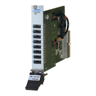
- Page 1 User Manual USB 2.0 Hub With Programmable Connect/Disconnect (Model No. 40-738) Issue 2.1 May 2017 pickeringtest.com pickering USB 2.0 HUB WITH CONNECT / DISCONNECT 40-738 Page (1)
- Page 2 © COPYRIGHT (2017) PICKERING INTERFACES. ALL RIGHTS RESERVED. No part of this publication may be reproduced, transmitted, transcribed, translated or stored in any form, or by any means without the written permission of Pickering Interfaces. Technical details contained within this publication are subject to change without notice.
- Page 3 Pickering Interfaces strives to fulfil all relevant environmental laws and regulations and reduce wastes and releases to the environment. Pickering Interfaces aims to design and operate products in a way that protects the environment and the health and safety of its employees, customers and the public. Pickering Interfaces endeavours to develop and manufacture products that can be produced, distributed, used and recycled, or disposed of, in a safe and environmentally friendly manner.
-
Page 4: Product Safety
If this product is heavy reference should be made to the safety instructions for provisions of lifting and moving. STATIC SENSITIVE To indicate that static sensitive devices are present and handling precautions should be followed. REED RELAY MODULE 40-110/115/120/125 USB 2.0 HUB WITH CONNECT / DISCONNECT 40-738 Page (IV) Page (IV) -
Page 5: Table Of Contents
Card Architecture ..............4.3 USB Switching ...............4.4 Example Code For Switching ..........4.6 Section 5 Connector Information ..............5.1 Section 6 Troubleshooting ................6.1 Over Current Protection............6.2 Section 7 Maintenance Information ............7.1 Switch Look-Up Table ............7.2 USB 2.0 HUB WITH CONNECT / DISCONNECT 40-738 Page (V) - Page 6 THIS PAGE INTENTIONALLY BLANK USB 2.0 HUB WITH CONNECT / DISCONNECT 40-738 Page (VI)
-
Page 7: Warnings And Cautions
Unused slots in the PXI/LXI chassis are populated with blanking plates to prevent access to user I/O signals that may be present. Blanking panels are available to order from Pickering in a variety of slot widths. If the product is not used in this manner for example by using an extender card then additional care must be taken to avoid contact with exposed signals. - Page 8 THIS PAGE INTENTIONALLY BLANK USB 2.0 HUB WITH CONNECT / DISCONNECT 40-738 Page (VIII)
- Page 9 ● USB Data Connection Via Vendor USB Driver ● 3 Year Warranty The 40-738 is a USB hub that allows data to be streamed to and from the USB devices by the system controller PCI system via the PXI backplane...
- Page 10 SECTION 1 - TECHNICAL SPECIFICATION pickering USB Test Devices Smart Phone Tablet Disk Drive Controller PC USB Test Equipment Power Sensor Data Acquisition Oscilloscope pickeringtest.com USB 2.0 HUB WITH CONNECT / DISCONNECT 40-738 Page 1.2...
- Page 11 Pickering Interfaces PXI drivers. Mechanical Characteristics: Single slot 3U PXI (CompactPCI card) Compatible with PXIe chassis hybrid slot Power Requirements +3.3V +12V -12V Up to 4.1A (0.5A on every Channel) pickeringtest.com USB 2.0 HUB WITH CONNECT / DISCONNECT 40-738 Page 1.3...
- Page 12 Systems such as LabVIEW RT. For other RTOS support Operating/Storage Conditions directives: Low-voltage safety EN61010-1:2001, contact Pickering. These drivers may be used with a variety of contact Pickering. These drivers may be used with a variety of Operating Conditions EMC Immunity EN61000-6-1:2001, Emissions EN55011:1998.
-
Page 13: Functional Description
PCB-PCB Interconnection J3-5 USB Host Controller Terminating Resistors R1-16 Control Logic Bridge U5-8 +3.3V Module PCI Bridge Configuration Configuration Mother Board Figure 2.1 - USB Hub 40-738: Functional Block Diagram USB 2.0 HUB WITH CONNECT / DISCONNECT 40-738 Page 2.1... - Page 14 SECTION 2 - TECHNICAL DESCRIPTION pickering THIS PAGE INTENTIONALLY BLANK USB 2.0 HUB WITH CONNECT / DISCONNECT 40-738 Page 2.2...
-
Page 15: Installation
Modular products require installation in a suitable PXI/LXI chassis. The module is designed for indoor use only. PREOPERATION CHECKS (UNPACKING) 1. Check the module for transport damage and report any damage immediately to Pickering Interfaces. Do not attempt to install the product if any damage is evident. -
Page 16: Hardware Installation
For a system comprising more than one chassis, turn ON the last chassis in the system followed by the penultimate, etc, and finally turn ON the external controller or chassis containing the system controller. 9. For Pickering Interfaces modular LXI installation there is no requirement to use any particular power up sequence. -
Page 17: Pickering Switch Driver Installation
Before any USB devices can be connected to the Hub and accessed, the switching part of the card must be controlled, to do this, first the Pickering standard switch driver must be installed. Select the driver required from the Pickering Switch Driver window and click “Next”: Note: Selecting the VISA Driver installs the Direct Driver at the same time. -
Page 18: Usb Driver Installation
USB Driver Installation No drivers are supplied by Pickering for the USB Hubs as they use standard Windows drivers, however separate Pickering drivers are required for the switching functions to be controlled. Insert PXI card allow Windows to install all USB components of the card standard windows drivers. A “Found New Hardware”... - Page 19 SECTION 3 - INSTALLATION pickering Expand out the appropriate PCI Standard PCI-to-PCI bridge tree structure as shown below: Make sure the components of the 40-738 module are installed, in particular: PCI standard PCI-to-PCI-Bridge 40-738-001 (switching functions on the module) Standard Enhanced PCI to USB Host Controller...
- Page 20 The Root Hub is a 5 port hub with two Generic USB Hubs connected. Three additional ports are shown but are unconnected for user operation. (refer to the functional diagram shown in Figure 4.1). USB 2.0 HUB WITH CONNECT / DISCONNECT 40-738 Page 3.6...
- Page 21 The Generic USB Hub should appear in the Properties window as shown below: There are two Generic USB Hubs each with four ports available for user connection via the front panel of the 40-738 module. These properties pages can be refreshed to show connected devices and expected power requirements.
- Page 22 However, this is not a problem for the operation of the module in Windows 7 as this is for legacy USB1 support and not required. The installed USB2 driver will operate the USB devices correctly. USB 2.0 HUB WITH CONNECT / DISCONNECT 40-738 Page 3.8...
-
Page 23: Testing Operation
Figure 3.2 - General Soft Front Panel Icon A selector panel will appear, listing all installed Pickering PCI, PXI or LXI switch cards and resistor cards. Click on the card you wish to control, and a graphical control panel is presented allowing operation of the card. - Page 24 SECTION 3 - INSTALLATION pickering THIS PAGE INTENTIONALLY BLANK USB 2.0 HUB WITH CONNECT / DISCONNECT 40-738 Page 3.10...
-
Page 25: Programming Guide
IVI Driver for Windows - pi40iv The pi40iv IVI (Interchangeable Virtual Instrument) driver supports all Pickering Interfaces PXI switch cards that are consistent with the Iviswtch class model - as are the great majority of cards in the System 40/45/50 ranges. It integrates well with LabWindows/CVI and LabVIEW, and is fully compatible with Switch Executive. - Page 26 With most drivers, before programming a Pickering card it is important to understand the basic architecture of Pickering cards. The switches on a Pickering card are organized into logical sub-units, each sub-unit containing a set of objects of similar type and use. These objects may be switches, digital outputs, digital inputs, resistors, power supplies etc, depending on the nature of the specific card.
-
Page 27: Card Architecture
Card Architecture The 40-738 Module contains two separate PCI devices; the USB Hub and the switching function. Both are controlled from the PXI backplane via an on-board PCI-PCI bridge. The USB Hub is controlled from the system’s PXI controller using standard Windows drivers, and the switching functions are controlled using standard Pickering switch drivers. -
Page 28: Usb Switching
SECTION 4 - PROGRAMMING GUIDE pickering USB Switching The switching function of the 40-738 USB Hub comprises a sub-unit for each USB channel, with a bit for each of the 4 signals. This is shown in the table below: SUB-UNIT... - Page 29 Figure 4.2 - Typical Switch Control Panel For The 40-738 Module It is recommended to switch all bits of a channel at the same time, switching the Data and Power lines independently...
-
Page 30: Example Code For Switching
ViString optionString = “Simulate=0,RangeCheck=1,QueryInstrStatus=1,Cache=1, DriverSetup=Model:40-738-001;”; Pi40iv_initWithOptions(“PXI2::15::INSTR”, 0, 0, optionString, &vi); // Set bit 2 in subunit 1 to logic 1 Pi40iv_Connect(“comA2”, “chA2”); Note: There are LabView versions of all driver functions. USB 2.0 HUB WITH CONNECT / DISCONNECT 40-738 Page 4.6... -
Page 31: Connector Information
SECTION 5 - CONNECTOR INFORMATION pickering SECTION 5 - CONNECTOR INFORMATION pickering Figure 5.1 - Front Panel Diagram For The 40-738-001 8-Channel USB Hub All Connectors Are Standard USB Type A USB 2.0 HUB WITH CONNECT / DISCONNECT 40-738 Page 5.1... - Page 32 SECTION 5 - CONNECTOR INFORMATION pickering THIS PAGE INTENTIONALLY BLANK USB 2.0 HUB WITH CONNECT / DISCONNECT 40-738 Page 5.2...
-
Page 33: Troubleshooting
PCI configuration, highlighting any potential configuration problems. Specific details of all installed Pickering switch cards are included. All the installed Pickering switch cards should be listed in the “Pilpxi information” section - if one or more cards is missing it may be possible to determine the reason by referring to the PCI configuration dump contained in the report, but interpretation of this information is far from straightforward, and the best course is to contact Pickering support: support@pickeringtest.com, if possible... -
Page 34: Over Current Protection
However, this will not disable power to the problem device so it is recommended you should disconnect such devices from the Hub. Figure 6.2 - Problem USB Device Automatically Disabled USB 2.0 HUB WITH CONNECT / DISCONNECT 40-738 Page 6.2... -
Page 35: Maintenance Information
For PXI modules which are supported in one of Pickering Interfaces’ Modular LXI Chassis (such as the 60-102B and 60-103B) no module software update is required. If the module was introduced after the LXI chassis was manufactured the module may not be recognized, in this case the chassis firmware may need upgrading. -
Page 36: Switch Look-Up Table
Channel 5 USB Power USB Ground USB Data Channel 6 USB Power USB Ground USB Data Channel 7 USB Power USB Ground USB Data Channel 8 USB Power USB Ground USB 2.0 HUB WITH CONNECT / DISCONNECT 40-738 Page 7.2... - Page 37 USB Port 4 USB Port 5 USB Port 6 USB Port 7 USB Port 8 Figure 7.1 - 40-738 USB Hub Daughter Board Component Layout Showing Positions of Switch Devices USB 2.0 HUB WITH CONNECT / DISCONNECT 40-738 Page 7.3...
- Page 38 SECTION 7 - MAINTENANCE INFORMATION pickering THIS PAGE INTENTIONALLY BLANK USB 2.0 HUB WITH CONNECT / DISCONNECT 40-738 Page 7.4...
Need help?
Do you have a question about the 40-738 and is the answer not in the manual?
Questions and answers