Table of Contents
Advertisement
I N S T A L L A T I O N ,
O P E R A T I O N
A N D
Touch Pilot Junior
M A I N T E N A N C E
I N S T R U C T I O N S
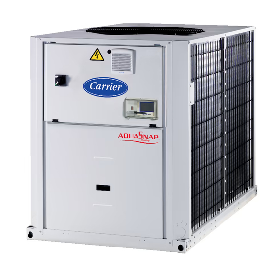
30RQSY
30RQS
For the operation of the control please refer to the
Touch Pilot Junior Control manual for the 30RB/30RQ 017-160 series
Reversible Air-to-Water Heat Pumps
30RQS/30RQSY 039-160 "A"
Nominal cooling capacity 40-160 kW
50 Hz
Original instructions
Advertisement
Table of Contents

Related Manuals for Carrier Aquasnap 30RQSY Series


Summarization of Contents
Introduction and Safety Precautions
30RQSY Units: Variable Available Pressure
Details on 30RQSY units for indoor installation with duct systems and variable fan speeds.
Equipment Inspection Upon Receipt
Instructions for verifying received units for damage, completeness, and nameplate data accuracy.
Installation Safety Considerations
Safety precautions and checks for unit reception and before startup, focusing on damage.
Equipment and Components Under Pressure
Information on pressure equipment, PED compliance, and operating environment considerations.
Maintenance Safety Guidelines
Guidelines for safe maintenance, logbook recommendations, and operating checks.
Repair Safety Considerations
Safety protocols for repair work, including refrigerant handling and electrical safety.
Unit Handling and Site Preparation
Moving the Unit Safely
Safety guidelines for moving the unit, emphasizing proper techniques and avoiding damage.
Siting the Unit Correctly
Recommendations for choosing a suitable installation location, ensuring accessibility and safety.
Pre-Start-Up Checks
Pre-start-up checks covering installation, refrigerant charge, electrical connections, and system diagrams.
30RQSY Unit Installation Specifics
General Installation Requirements
Each fan controlled by VSD requires separate duct systems for optimal operation.
Duct Connection Guidelines
Details on connecting ductwork to 30RQSY units for suction and discharge air.
Dimensions and Clearances for Installation
30RQS 039-078 Units Dimensions
Dimensional drawings and clearances for 30RQS 039-078 units.
30RQS 080-160 Units Dimensions
Dimensional drawings and clearances for 30RQS 080-160 units.
30RQSY 039-045 Units Dimensions
Dimensional drawings and clearances for 30RQSY 039-045 units without filter frame.
30RQSY 080-120 Units Dimensions
Dimensional drawings and clearances for 30RQSY 080-120 units.
30RQSY 140-160 Units Dimensions
Dimensional drawings and clearances for 30RQSY 140-160 units.
30RQS/RQSY 080-160 Buffer Tank Module Dimensions
Dimensional drawings and clearances for 30RQS/RQSY 080-160 units with buffer tank module.
Physical Data: 30RQS Units
Sound Levels for 30RQS
Sound power and pressure levels for standard 30RQS units and units with option 15LS.
Dimensions of 30RQS Units
Length, depth, and height dimensions for 30RQS units, with and without buffer tank module.
Electrical Data: 30RQS Units
30RQS Power Circuit Details
Nominal power supply, voltage range, and control circuit supply details for 30RQS units.
Physical Data: 30RQSY Units
Sound Levels for 30RQSY
Sound levels for 30RQSY units with 160 Pa external static pressure.
Dimensions of 30RQSY Units
Length, width, and height dimensions for 30RQSY units, including variations for option 23B.
Electrical Data: 30RQSY Units
30RQSY Power Circuit Details
Power supply, voltage range, and control circuit details for 30RQSY units.
30RQS & 30RQSY Electrical Data
Short-Circuit Stability Current (TN System)
Short-circuit stability current values for 30RQS/RQSY units with unspecified upstream protection.
Hydronic Module Electrical Data
Electrical data for single and dual low-pressure pumps used in hydronic modules.
Compressor Electrical Data
Compressor electrical data including nominal current, max current, LRA, and cosine phi.
Application Data and Operating Ranges
Cooling Mode Operating Range
Specifies operating ranges for cooling mode for standard 30RQS/RQSY units.
Heating Mode Operating Range
Specifies operating ranges for heating mode for standard 30RQS/RQSY units.
Water Heat Exchanger Flow Rate
Details water flow rates for 30RQS/RQSY units, including minimum, maximum, and dual pump rates.
Electrical Connections and Wiring
Power Supply Requirements
Guidelines for power supply specifications, voltage range, and warnings about improper supply.
Recommended Wire Sections
Table providing recommended wire sections for power entry cables based on unit size.
Field Control Wiring Precautions
Important precautions for field control wiring and connection of interface circuits.
Water Connections and Flow Control
Water Connection Precautions
General precautions for water circuit design, connections, and material compatibility.
Frost Protection for Water Circuits
Details on frost protection for heat exchangers and hydronic components, including winter position.
Protection Against Cavitation (Option 116)
Explains anti-cavitation protection for pumps and minimum entering pressure requirements.
Nominal System Water Flow Control
General Information: Units Without Hydronic Module
How to set nominal flow rate using a manual valve for units without hydronic modules.
Control Procedure: Pressure Differential Setpoint
How to adjust pressure differential setpoint to control flow rate for variable-speed pumps.
Variable-Speed Pump: Temperature Difference Control
Explains temperature difference control for units with variable-speed pumps.
Plate Heat Exchanger Pressure Drop
Graphs showing pressure drop for plate heat exchangers in units without hydronic modules.
Pump Pressure/Flow Rate Curves
Pump performance curves for low-pressure and high-pressure pumps in hydronic modules.
Unit Start-Up Procedures
Preliminary Checks Before Start-Up
Essential pre-start-up checks including reading instructions and verifying connected equipment.
Actual Unit Start-Up Process
Guidelines for supervised start-up, thermal load application, and control tests.
Master/Slave Operation of Two Units
How to configure and operate two units in a master/slave assembly.
Supplementary Electric Resistance Heaters
Information on installing and controlling supplementary electric heaters for capacity reduction.
Major System Components Overview
Compressors and Lubrication
Details on hermetic scroll compressors, lubrication, and compatibility warnings.
Air Heat Exchangers
Description of air heat exchangers, their construction, and frost protection heaters.
Electronic Expansion Valve (EXV)
Details on the EXV, its stepper motor, and control via the EXV board.
Water Evaporator/Condenser
Description of the plate heat exchanger, its water connections, and thermal insulation.
High-Pressure Safety Switch
Information on automatically resetting safety pressure switches on the high-pressure side.
Control Box Features
Description of the control box, including electric heaters for condensation prevention.
Specific Unit Features and Options
30RQSY: Fan Static Pressure Details
Selection based on pressure drop and correction factors for 30RQSY units.
Partial Heat Reclaim with Desuperheaters (Option 49)
Installation and operation of heat reclaim using desuperheaters.
Brine Option (5B & 6B): Frost Protection
Frost protection for brine circuits depends on antifreeze amount and controls.
Standard Maintenance Procedures
Level 1 Maintenance: User Tasks
Simple weekly maintenance tasks for users, including visual inspections and alarm checks.
Level 2 Maintenance: Skilled Tasks
Monthly/annual maintenance requiring specific skills, covering electrical, mechanical, and water circuits.
Level 3 Maintenance: Advanced Tasks
Advanced maintenance requiring manufacturer/authorised agent skills, including component replacement.
Air Heat Exchanger Cleaning
Recommendations for inspecting and cleaning air heat exchangers to ensure optimal operation.
Refrigerant Volume Check
How to check refrigerant charge correctness using subcooling in cooling mode.
Need help?
Do you have a question about the Aquasnap 30RQSY Series and is the answer not in the manual?
Questions and answers