Table of Contents
Advertisement
Quick Links
Advertisement
Table of Contents

Related Manuals for Carrier 30RQM 160


Summary of Contents for Carrier 30RQM 160
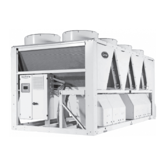
- Page 1 M A I N T E N A N C E I N S T R U C T I O N S Unit with low-noise option Unit with low-noise option Reversible air-to-water heat pump 30RQM 160-520 30RQP 160-520 Nominal heating capacity 170 - 540 kW Nominal cooling capacity 160 - 510 kW...
-
Page 2: Table Of Contents
3.5 - Distance to the wall ................................13 4 - PHYSICAL AND ELECTRICAL DATA FOR 30RQM AND 30RQP UNITS ............14 4.1 - Physical data 30RQM 160-520 ............................. 14 4.2 - Physical data 30RQP 160-520 ............................... 15 4.3 - Electrical data 30RQM 160-520 ............................16 4.4 - Electrical data 30RQP 160-520 ............................. - Page 3 11.9 - Characteristics of R-410A ..............................55 11.10 - Check of power factor correction capacitors ........................55 12 - UNIT START-UP CHECKLIST FOR INSTALLERS PRIOR TO CONTACTING CARRIER SERVICE ..56 This manual applies to the following units: 30RQM: Standard reversible heat pump.
-
Page 4: Introduction
1 - INTRODUCTION Safety can only be guaranteed if these instructions are carefully Prior to the initial start-up of the 30RQM/30RQP units, everyone followed. Failure to do so may result in damage to the equipment involved in the works should be thoroughly familiar with these instructions and with the characteristics of the installation site, and physical injury. - Page 5 The presence of oil at the outlet orifice is a useful indicator that refrigerant has leaked. Keep this orifice clean to ensure that any leaks Carrier recommends the following table as a guide to completing the are obvious. The calibration of a valve that has leaked is generally monitoring and maintenance register (logbook) required by EN lower than its original calibration.
- Page 6 Refrigerant type: R-410A Please contact Carrier Service for this type of test. The test Global Warming Potential (GWP): 2088 principle set out here by Carrier does not involve removal of the pressure switch: CAUTION: Verify and record the nominal values for activation of the...
-
Page 7: Installation Safety Considerations
by a short circuit in a motor or freezing of the BPHE), remove We recommend that standard EN 378-3 Annex 3 is applied. the complete charge using a recovery unit and store the Never apply an open flame or live steam to a refrigerant refrigerant in mobile containers. -
Page 8: Pressure Equipment And Components
2 - PRELIMINARY CHECKS 2.2 - Handing and positioning 2.2.1 - Handling 2.1 - Check equipment received See the section on “Installation safety considerations” . • Check that the unit has not been damaged during transport In some cases, uprights are added for transporting and handling and that no parts are missing. -
Page 9: Repair Safety Considerations
• Compare the complete system with the refrigeration system NOTE: If Carrier's recommendations (power and water and power circuit diagrams. connections and installation) are not observed, then no claims •... - Page 10 3 - DIMENSIONS AND CLEARANCES 3.1 - 30RQM/30RQP 160-230 WITHOUT HYDRAULIC MODULE 30RQP only Sizes 210-230 Power connection Key: All dimensions are in mm. Clearances required for maintenance and air flow Clearance recommended for coil removal Water inlet Water outlet Air outlet, do not obstruct Control box NOTE: Non-contractual drawings. When designing a system, refer to the certified WITH HYDRAULIC MODULE dimensional drawings provided with the unit or available on request.
- Page 11 WITH WATER BUFFER TANK MODULE Main hydraulic connection Electrical power connection Key: All dimensions are in mm. Clearances required for maintenance and air flow Clearance recommended for coil removal Water inlet Water outlet Air outlet, do not obstruct Control box NOTE: Non-contractual drawings. When designing a system, refer to the certified dimensional drawings provided with the unit or available on request.
-
Page 12: Commissioning
3.2 - 30RQM/30RQP 240-330 WITHOUT HYDRAULIC MODULE 30RQP only Size 330 Power connection Sizes 270-310-330 Key: All dimensions are in mm. Clearances required for maintenance and air flow Clearance recommended for coil removal Water inlet Water outlet Air outlet, do not obstruct Control box NOTE: Non-contractual drawings. When designing a system, refer to the certified dimensional drawings provided with the unit or available on request. -
Page 13: Dimensions And Clearances
WITH WATER BUFFER TANK MODULE Main hydraulic connection Electrical power connection Key: All dimensions are in mm. Clearances required for maintenance and air flow Clearance recommended for coil removal Water inlet Water outlet Air outlet, do not obstruct Control box NOTE: Non-contractual drawings. When designing a system, refer to the certified dimensional drawings provided with the unit or available on request. -
Page 14: 30Rqm/30Rqp 240-330 (With And Without Hydraulic Module)
3.3 - 30RQM/30RQP 380-520 WITHOUT HYDRAULIC MODULE 30RQP only Sizes 430-470-520 Power connection Key: All dimensions are in mm. Clearances required for maintenance and air flow Clearance recommended for coil removal Water inlet Water outlet Air outlet, do not obstruct Control box NOTE: Non-contractual drawings. When designing a system, refer to the certified dimensional drawings provided with the unit or available on request. -
Page 15: 30Rqm/30Rqp 380-520 (With And Without Hydraulic Module)
WITH WATER BUFFER TANK MODULE Main hydraulic connection Electrical power connection Key: All dimensions are in mm. Clearances required for maintenance and air flow Clearance recommended for coil removal Water inlet Water outlet Air outlet, do not obstruct Control box NOTE: Non-contractual drawings. When designing a system, refer to the certified dimensional drawings provided with the unit or available on request. -
Page 16: Installation Of Multiple Heat Pumps
It is recommended to install multiple heat pumps in a single row, arranged as shown in the example below, to avoid recycling of air from one unit to another. If the floor space does not allow this arrangement, contact your Carrier distributor to assess the various installation options. 3.5 - Distance to the wall To guarantee correct operation in most cases: If h <... -
Page 17: Physical And Electrical Data For 30Rqm And 30Rqp Units
4 - PHYSICAL AND ELECTRICAL DATA FOR 30RQM AND 30RQP UNITS 4.1 - Physical data 30RQM 160-520 30RQM Sound levels Standard unit Sound power dB(A) Sound pressure at 10 m dB(A) Standard unit + option 15 Sound power dB(A) Sound pressure at 10 m... -
Page 18: Physical Data 30Rqp 160-520
4.2 - Physical data 30RQP 160-520 30RQP Sound levels Standard unit Sound power dB(A) Sound pressure at 10 m dB(A) Standard unit + option 15 Sound power dB(A) Sound pressure at 10 m dB(A) Standard unit + option 15LS Sound power dB(A) Sound pressure at 10 m dB(A) -
Page 19: Electrical Data 30Rqm 160-520
4.3 - Electrical data 30RQM 160-520 30RQM Power circuit Nominal voltage V-ph-Hz 400 - 3 -50 Voltage range 360 - 440 Control circuit supply 24 V via internal transformer Nominal unit current draw Circuit A&B Maximum unit input power Circuit A&B... -
Page 20: Electrical Data Notes For The Hydraulic Module
Operating conditions for which the motor is specifically designed I - Altitudes above sea level < 1000 II - Ambient air temperature °C < 40 III - Maximum operating temperature °C Please refer to the operating conditions given in this manual or in the specific conditions in the Carrier selection programs. IV - Potentially explosive atmospheres Non ATEX environment (1) Additional electrical data required by regulation No. 640/2009 concerning the application of directive 2005/32/EC on the eco-design requirements for electric motors. (2) Item number imposed by regulation No. 640/2009, annex I2b. (3) Description given by regulation No. 640/2009, annex I2b. (4) Above 1000 m, a degradation of 3% for each 500 m should be taken into consideration. (5) To obtain the maximum input power for a unit with hydraulic module, add the maximum unit input power from the electrical data table to the pump power input. (6) To obtain the maximum unit operating current draw for a unit with hydraulic module add the maximum unit current draw from the electrical data table to the pump current draw. For the low pressure dual-pump motors for 30RQM/30RQP 160-520 units (option 116U) Description... - Page 21 Operating conditions for which the motor is specifically designed I - Altitudes above sea level < 1000 II - Ambient air temperature °C < 40 III - Maximum operating temperature °C Please refer to the operating conditions given in this manual or in the specific conditions in the Carrier selection programs. IV - Potentially explosive atmospheres Non ATEX environment (1) Additional electrical data required by regulation No. 640/2009 concerning the application of directive 2005/32/EC on the eco-design requirements for electric motors. (2) Item number imposed by regulation No. 640/2009, annex I2b. (3) Description given by regulation No. 640/2009, annex I2b. (4) Above 1000 m, a degradation of 3% for each 500 m should be taken into consideration. (5) To obtain the maximum input power for a unit with hydraulic module, add the maximum unit input power from the electrical data table to the pump power input. (6) To obtain the maximum unit operating current draw for a unit with hydraulic module add the maximum unit current draw from the electrical data table to the pump current draw. For the high pressure single- and dual-pump motors for 30RQM/30RQP 160-520 units (options 116S and 116W)
-
Page 22: Compressor Usage And Electrical Data
4.7 - Compressor usage and electrical data I Nom I Max I Max Cosinus Circuit 160 180 210 230 240 270 310 330 380 430 470 520 Un-10 % Phi Max 0.89 00PSG001961100A 00PSG001748000A 0.89 I Nom Nominal current draw (A) at standardised Eurovent equivalent conditions (see definition of conditions under nominal unit current draw) I Max Maximum operating current (A) Locked rotor current (A) Cos phi Max @I Max, 400 V, 50 Hz... -
Page 23: Electrical Connection
Calculate the maximum deviation from the 400 V average: which will invalidate the Carrier warranty. If the phase imbalance exceeds 2% for voltage, or 10% for current, contact (AB) = 406 - 400 = 6... -
Page 24: Recommended Wire Sections
The following is only to be used as a guideline, and does not (90°C) with copper core; routing in accordance with table 52C make Carrier in any way liable. After wire sizing has been of the standard. The maximum ambient temperature is 45°C. -
Page 25: Power Cable Access Routing
5.5 - Power cable access routing 5.6 - Field control wiring The power cables are routed into the electrics box on IMPORTANT: Field connection of interface circuits carries 30RQM/30RQP units from underneath. safety risks: any modifications to the electrical box must ensure that the equipment remains compliant with local regulations. -
Page 26: Application Data
Water inlet temperature at start-up °C Water outlet temperature during operation °C Air heat exchanger Outdoor ambient operating temperature °C (5)(6) Available static pressure Standard unit (for outdoor installation) (1) For an application requiring start-up at less than 8°C, contact Carrier to select a unit using the Carrier electronic catalogue. (2) The use of antifreeze protection is required if the water outlet temperature is below 5°C (3) For applications requiring operation above a water outlet temperature of 20°C, contact Carrier to select a unit using the Carrier electronic catalogue. (4) For operation at an ambient temperature of 0°C down to -20°C (cooling mode), the heat pump must be a 30RQM unit equipped with option 28 "Winter operation" or a 30RQP unit. (5) For operation at an ambient temperature of 0°C down to -10°C (heating mode), the heat pump must Outlet water temperature, °C be equipped with option 252 "Coil defrost heater"... -
Page 27: Maximum Water Flow (Units Without Hydraulic Module)
6.3 - Maximum water flow (units without hydraulic 6.6 - Maximum system water volume module) Units supplied with a hydraulic module may include an expansion tank which limits the volume in the water loop (option 293). The maximum water flow is shown in the table on the next page. If the system's flow exceeds the unit's maximum value, it can be The table below gives the maximum loop volume for pure water bypassed as shown in the diagram. -
Page 28: Pressure Drop Curves For The Exchanger And Standard Water Inlet/Outlet Piping
6.8 - Pressure drop curves for the exchanger and standard water inlet/outlet piping Data applicable for pure water at 20°C. 30RQM/30RQP 160-310 units Flow rate, l/s 1 30RQM/30RQP 160-180-210 2 30RQM/30RQP 230 3 30RQM/30RQP 240-270 4 30RQM/30RQP 310 30RQM/30RQP 330-520 units Flow rate, l/s 5 30RQM/30RQP 330-380-430 6 30RQM/30RQP 470 7 30RQM/30RQP 520... -
Page 29: Water Connections
Where additives • Install thermometers in both the water inlet and outlet or other fluids than those recommended by Carrier are used, pipes. ensure that these are not considered gases, and that they are •... -
Page 30: Hydraulic Connections
7.2 - Hydraulic connections The hydraulic module options are only compatible with closed heat transfer fluid loops. The use of the hydraulic kit on open loop systems is prohibited. Schematic diagram of the water circuit without the hydraulic module Schematic diagram of the water circuit with the hydraulic module Option Option 25 25... - Page 31 Figure 1: Water connections without hydraulic module Figure 2: Water connections with hydraulic module Example: Single-pump Example: Dual-pump Coupling for expansion Raccord pour vase Coupling for expansion vessel (option 293) Raccord pour vase d’expansion (option 293) vessel (option 293) d’expansion ( option 293) See legend on the previous page. Figure 3: Water connections with hydraulic module and with buffer tank module option...
-
Page 32: Water Flow Detection
(0.5 bar maximum). If the heat transfer each extension in order to protect the water pipes down to fluid does not meet Carrier's recommendations, a nitrogen outdoor temperatures of -20°C. The anti-freeze and heater blanket must be applied immediately. -
Page 33: Protection Against Cavitation (With Option 116)
7.6 - Operation of two units in Master/Slave mode (option 58) The customer must connect both units with a communication bus in 0.75 mm² twisted, shielded cable (contact Carrier Service for the installation). All the parameters required for the master/slave function must be configured using the Service configuration menu. -
Page 34: Auxiliary Electric Heaters
Example 3: operation in series - control on water Example of additional electric heaters outlet for a combination of units Operating range for which the heat pump output is less than the building Master unit thermal load Operating range for which the heat pump output is greater than the building Slave unit thermal load Electrical boxes for Master and Slave units Stage 1 Stage 2 Water inlet Stage 3 Stage 4 (safety) Water outlet Variation of the heat pump output with air temperature Water pumps for each unit (included in units with hydraulic module) -
Page 35: Rated Installation Water Flow Control
These data can be obtained either from the performance tables included in the technical documentation (for cases where the To reduce the system's hydraulic network pressure drop: DT is 5 K) or from the Carrier Electronic Catalogue selection program for all other applicable DT's. •... -
Page 36: Units With Hydraulic Module And Fixed Speed Pump
Contact Carrier Service to discuss the implementation of the NOTE: procedures set out below. If the network has an excessive pressure drop in relation to the 8.3.1 - Cleaning procedure for the water circuit... -
Page 37: Units With Hydraulic Module And Variable Speed Pump - Temperature Differential Control
If the value read is greater than the specified value, reduce the maximum and minimum pump supply frequency values. the pressure differential setpoint on the user interface to Contact Carrier Service to discuss the implementation of the reduce the flow value; procedures set out below. -
Page 38: Pump Pressure/Flow Rate Curves
8.6 - Pump pressure/flow rate curves Units with hydraulic module (fixed speed pump or variable speed pump at 50 Hz) Data applicable for: Fresh water at 20°C. Refer to the chapter "Exchanger water flow" for the maximum water flow values. In case of use of ethylene-glycol, the maximum flow rate is reduced. - Page 39 8.6.2 - 30RQM/30RQP low pressure pumps Single pumps Water flow rate, l/s 1 30RQM/30RQP 160-180 30RQM/30RQP 210-230 30RQM/30RQP 240-270-310 30RQM/30RQP 330-380-430 30RQM/30RQP 470-520 Dual pumps Water flow rate, l/s 1 30RQM/30RQP 160 2 30RQM/30RQP 180 3 30RQM/30RQP 210-230 4 30RQM/30RQP 240-270-310 5 30RQM/30RQP 330-380-430 6 30RQM/30RQP 470 7 30RQM/30RQP 520...
-
Page 40: Available Static System Pressure
8.7 - Available static system pressure Units with hydraulic module (fixed speed pump or variable speed pump at 50 Hz) Data applicable for: Fresh water at 20°C. Refer to the chapter "Water exchanger water flow" for the maximum water flow values. In case of use of ethylene-glycol, the maximum flow rate is reduced. - Page 41 8.7.2 - 30RQM/30RQP low pressure pumps Single pumps Sizes 160-270 Sizes 310-520 Water flow rate, l/s Water flow rate, l/s 30RQM/30RQP 160-180 30RQM/30RQP 310 30RQM/30RQP 210 30RQM/30RQP 330-380-430 30RQM/30RQP 230 30RQM/30RQP 470 30RQM/30RQP 240-270 30RQM/30RQP 520 Dual pumps Sizes 160-230 Sizes 240-520 Water flow rate, l/s Water flow rate, l/s 30RQM/30RQP 160 30RQM/30RQP 240-270 30RQM/30RQP 180 30RQM/30RQP 310 30RQM/30RQP 210 30RQM/30RQP 330-380-430 30RQM/30RQP 230 30RQM/30RQP 470 30RQM/30RQP 520...
-
Page 42: Main Components Of The Unit And Operating Characteristics
9 - MAIN COMPONENTS OF THE UNIT AND If this is not the case, there might be a leak or an oil trap in the OPERATING CHARACTERISTICS circuit. If there is an oil leak, find and repair it, then refill with refrigerant and oil. -
Page 43: Electronic Expansion Valve (Exv)
(Pulse Width Modulation). Fan start-up/shut-down and the working range frequency setpoint is controlled by the 9.7 - Refrigerant accumulator with built-in filter drier Carrier Controller through RS485 communication using the The refrigerant charge required in cooling mode is greater than LEN Protocol. -
Page 44: Medium And Low Temperature Brine Solution Option (Option 6B)
9.13 - Low temperature brine solution option (Option 6B) 9.13.2 - Required glycol concentration Ethylene and Propylene glycol freezing curve Brine solution production from 0°C to -8°C is only possible with the low-temperature brine solution option (6B). The unit is equipped with insulation on the suction tubes. The insulation is reinforced on the low-temperature brine solution option. -
Page 45: Fan Arrangement
• The screen menus can be adapted for different users (end client, maintenance personnel, Carrier engineer). In case of fan failure (e.g. motor disconnected) the variable drive • Unit setting and use are secure. Password protection prevents will detect this problem and an alert will be sent to the user unauthorised access to advanced parameters. -
Page 46: Options
The noise level into the ductwork and radiated around the unit is also related to the pressure drop. Please refer to the Carrier Electronic catalog to evaluate the impact of the estimated duct system on the 30RQP unit operating conditions. -
Page 47: Installation
10.4 - Installation 10.5 - Nominal and maximum air flows per circuit (A and B) for 30RQP sizes IMPORTANT: When the 30RQP units operate in heating mode, dehumidification of the room air and defrosting of the air heat 30RQP Circuit A Circuit B exchangers generate a large amount of condensate that must Nominal/maximum air flow (l/s) - Page 48 Principle of the installation of the ducts Solution 1 Solution 2 each fan has its own duct 2 fans can used the same duct 1 Fan motor access hatches (provide a 700 x 700 mm hatch) for each single and dual duct Rules for a correct ductwork At the outlet of each duct, provide an access hatch with a minimum size of 700 x 700 mm to allow motor replacement...
-
Page 49: Partial Heat Reclaim Using Desuperheaters (Option 49)
10.7 - Partial heat reclaim using desuperheaters (option 49) This option permits the production of free hot water using heat reclaim by desuperheating the compressor discharge gases. The option is available for the whole 30RQM/30RQP range. A plate heat exchanger is installed in series with the air heat exchanger coils on the compressor discharge line of each circuit. The control configuration for the desuperheater option is factory assembled (see chapter 10.7.8 "Control configuration"). - Page 50 10.7.2 - 30RQM/30RQP 160-230 (equipped with desuperheater option 49) 2'' Victaulic 2410 HT UNIT WITH HYDRAULIC MODULE 1500 Key: All dimensions are in mm. Clearances required for maintenance and air flow Clearance recommended for coil removal Water inlet Water outlet Control box NOTE: Non-contractual drawings. When designing a system, refer to the certified dimensional drawings provided with the unit or available on request.
- Page 51 10.7.3 - 30RQM/30RQP 240-330 (equipped with desuperheater option 49) 2'' Victaulic 3604 HT UNIT WITH HYDRAULIC MODULE 1500 1495 509 1500 Key: All dimensions are in mm. Clearances required for maintenance and air flow Clearance recommended for coil removal Water inlet Water outlet Control box NOTE: Non-contractual drawings. When designing a system, refer to the certified dimensional drawings provided with the unit or available on request.
- Page 52 10.7.4 - 30RQM/30RQP 380-520 (equipped with desuperheater option 49) 2'' Victaulic 4797 HT UNIT WITH HYDRAULIC MODULE 1500 2730 339 Key: All dimensions are in mm. Clearances required for maintenance and air flow Clearance recommended for coil removal Water inlet Water outlet Control box NOTE: Non-contractual drawings. When designing a system, refer to the certified dimensional drawings provided with the unit or available on request.
- Page 53 10.7.5 - Installation and operation of the heat reclaim with During the unit installation the heat reclaim plate heat exchangers must be insulated and frost protected, if required. desuperheater option The 30RQM/30RQP units with the desuperheater option (No. Please refer to the typical installation diagram below for the 49) are supplied with one heat exchanger per refrigerant circuit.
- Page 54 °C on each circuit. Air heat exchanger (evaporator) Entering air temperature °C Available static pressure Desuperheater Note: Do not exceed the maximum operating temperature. (plate heat exchanger pressure drop curves) For an application that requires operation below 6.8°C, contact Carrier. The entering water temperature at start-up must not be lower than 25°C. For installations with a lower temperature a three-way valve is necessary. *** For operation down to -20°C the unit must be equipped with option 28 (winter operation). In addition the unit must either be equipped with the frost protection option or the water loop must be protected by the installer by adding a frost protection solution. Maximum outside temperatures: During storage and transport of the 30RQM/30RQP units the minimum and maximum temperatures must not exceed -20°C and +48°C. It is recommended to observe these temperatures during transport by container. 10.7.8 - Control configuration with the desuperheater option...
-
Page 55: Other Options
Soft Starter Electronic starter on each compressor Reduced start-up current 30RQM/30RQP 160-520 Winter operation down to Fan speed control of lead fan for each circuit using a variable Stable unit operation for outside air temperature from 0°C down 30RQM 160-520 -20°C frequency drive to -20°C in cooling mode Water exchanger frost Electric heater on the water exchanger and the water piping Water exchanger module frost protection between 0°C and -20°C 30RQM/30RQP protection... -
Page 56: Standard Maintenance
A Carrier Service maintenance In these cases, the following maintenance operations are contract is the best way to ensure the maximum operating life for... -
Page 57: Level 3 (Or Higher) Maintenance
(e.g. nitrogen) for Specific Carrier-approved products for cleaning RTPF coils longer durations. with untreated fins are available from the Carrier spare parts network. The use of any other product is strictly prohibited. After the cleaning product is applied, rinsing with water is... -
Page 58: Water Heat Exchanger Maintenance
In case of any alarm or persistent problem related to the variable must be used when working on the refrigerant circuit (pressure frequency drive, contact Carrier Service. measurement, charge transfer, etc.). The variable drives fitted on 30RQM/30RQP units do not require 11.10 - Check of power factor correction capacitors... -
Page 59: Unit Start-Up Checklist For Installers Prior To Contacting Carrier Service
12 - UNIT START-UP CHECKLIST FOR INSTALLERS PRIOR TO CONTACTING CARRIER SERVICE (USE FOR MACHINE FILE) Preliminary information Job name: ....................................... Location: ........................................ Installing contractor: ..................................... Distributor: ......................................Start-up performed by: .............. Date: ....................Equipment Model 30RQM/30RQP: ............... Serial number ................ - Page 60 Unit start-up The chilled water pump contactor has been correctly cabled with the chiller The oil level is correct The unit has been checked for leaks (including couplings) Locate, repair, and report any refrigerant leaks ..............................................................................................................................Check voltage imbalance: AB....AC....
- Page 61 Carry out the QUICK TEST function (Consult Carrier Service): Check and log on to the user menu configuration Load sequence selection ..............................Capacity ramp loading selection ............................Start-up delay ..................................Pump control ..................................Setpoint shift mode................................Night mode capacity limitation ............................
- Page 62 Administrative number: 10018 , 02.2017 - supercedes no.: 10018 , 10.2016 Manufacturer: Carrier SCS, Montluel, France The manufacturer reserves the right to change any product specifications without notice. Printed in the European Union...
Need help?
Do you have a question about the 30RQM 160 and is the answer not in the manual?
Questions and answers