Table of Contents
Advertisement
Advertisement
Table of Contents

Subscribe to Our Youtube Channel
Related Manuals for Carrier AQUASNAP 30RA


Summary of Contents for Carrier AQUASNAP 30RA
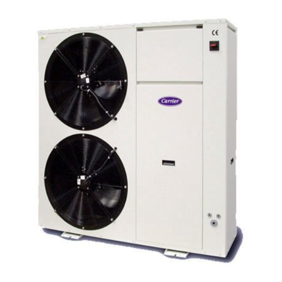
- Page 1 AQUASNAP 30RA / 30RH INSTALLATION, OPERATION AND MAINTENANCE INSTRUCTIONS...
-
Page 2: Table Of Contents
30RA/30RH Air-cooled liquid chillers and reversible air-to-water heat pumps with integrated hydronic module For the use of the control system, refer to the Pro-Dialog Plus control manual. Contents Physical data ... Electrical data ... Dimensions and location of hydraulic connections ... Clearance and electric cables ... -
Page 3: Physical Data
30RA Physical data and electrical data - Model RA Table I: Physical data - Model RA 30RA Net cooling capacity* Operating weight without hydronic module with hydronic module Refrigerant charge R-407C Compressor Evaporator Net water volume Water connections (MPT gas) Maximum water pressure (unit without hydronic module) Hydronic module... - Page 4 30RH Physical data and electrical data - Model RH Table I: Physical data - Model RH 30RH Net cooling capacity* Net heating capacity** Operating weight without hydronic module with hydronic module Refrigerant charge R-407C Compressor Control system Refrigerant-water heat exchanger Net water volume Water connections (MPT gas) Maximum water pressure...
-
Page 5: Dimensions And Location Of Hydraulic Connections
30RA/30RH Dimensions and location of hydraulic connections (mm) Mod. 30RA 017 - 021 Mod. 30RH 017 1328 175 105 1068 1. Water inlet Main switch Grommet: 1 Pg 29 and 2 Pg 16 for power supply and control cables entry GB - 4 12x20 2. -
Page 6: General Information And Hydronic Module
For other applications, please consult Carrier. • In the case of heat pump operation with an outdoor temperature of less than 0 C the unit must be installed at least 300 mm above ground level. -
Page 7: Water Connections
30RA/30RH Water connections Typical water circuit diagram for units without hydronic module Typical water circuit diagram for units with hydronic module NOTE: If the automatic fill kit option is used on the unit, fitting an extra charging valve is unnecessary. GB - 6 Legend for units without hydronic module:... - Page 8 30RA/30RH Water connections Ethylene glycol curve Make the plate heat exchanger hydraulic connections with the necessary components, using material which will guarantee that the screwed joints are leakproof. The typical hydraulic circuit diagram shows a typical water circuit installation in an air conditioning system. For an application with a water circuit, the following recommendations must be taken into account: 1.
-
Page 9: Water Connections
30RA/30RH Water connections Water pressure drop of the unit without hydronic module Outlet available static pressure of the unit with hydronic module GB - 8 Water flow rate, l/s Water flow rate, l/s A. 30RA-RH 017 B. 30RA-RH 021 C. 30RA-RH 026 D. -
Page 10: Electrical Connections
WARNING: Operation of the unit on improper line voltage constitutes abuse and is not covered by the Carrier warranty. IMPORTANT: To ensure the correct unit power supply (cable entry, conductor cross section, protection devices etc.), consult the... -
Page 11: Electronic Control
30RA/30RH Refrigerant charge and electronic control Undercharge If there is not enough refrigerant in the system, this is indicated by gas bubbles in the moisture sight glass. There are two possibilities: • Small undercharge (bubbles in the sight glass, no significant change in suction pressure). -
Page 12: Start-Up
30RA/30RH Start-up, compressor and pump replacement, unit protection devices Start-up Unit start-up is done by the electronic control described above, and must always be carried out under the supervision of a qualified air conditioning engineer. Necessary checks/precautions before start-up - Ensure that all electrical connections are properly tightened. - Ensure that the unit is level and well-supported. -
Page 13: Unit Protection Devices
Water entering temp. (at shut-down) Coil Air entering temperature Contact Carrier if an entering water temperature lower than 7.8 C is necessary. In case of operation with a leaving temperature of less than 5 C, it is necessary to add ethylene glycol to the water in circulation. -
Page 14: General Maintenance
Always wear the protective gloves and safety glasses. Pay attention to burns when brazing. - Use only Carrier Original Spare Parts when repair is required. Always make sure the spare parts are installed correctly. Always install the spare parts in the original position. -
Page 15: Troubleshooting
30RA/30RH Troubleshooting A list of possible faults, as well as the probable cause and suggested solutions is shown as follows. In the event of a unit malfunction it is recommended to disconnect the power supply and ascertain the cause. Symptoms Cause REMEDY Unit does not start:... - Page 16 L010126H27 - 0405 Via R. Sanzio, 9 - 20058 Villasanta (MI) Italy - Tel. 039/3636.1 The manufacturer reserves the right to change any product specifications without notice. Order No. 13024-74 April 2005. Supersedes Order No. 13024-74, June 2004. Printed in Italy...
Need help?
Do you have a question about the AQUASNAP 30RA and is the answer not in the manual?
Questions and answers