Table of Contents
Advertisement
Quick Links
Advertisement
Table of Contents

Related Manuals for Chauvet Professional Well Panel


Summary of Contents for Chauvet Professional Well Panel
- Page 1 User Manual Model ID: WELLPANEL...
- Page 2 Edition Notes The WELL Panel User Manual includes a description, safety precautions, installation, programming, operation and maintenance instructions for the WELL Panel as of the release date of this edition. Trademarks Chauvet, Chauvet Professional, the Chauvet logo, and WELL are registered trademarks or trademarks of Chauvet &...
-
Page 3: Table Of Contents
Static Mode ........................17 Red Shift ........................17 Dimmer Profiles......................17 White Balance ........................ 17 LED Frequency ......................17 Line Voltage Power Loss Mode ..................18 Run Time........................18 Back Light ........................18 System Information ......................18 WELL Panel User Manual Rev. 4... - Page 4 Table of Contents Factory Reset......................... 18 Master/Slave ........................18 5. Maintenance................Product Maintenance ..................6. Technical Specifications ............Contact Us ..................Warranty & Returns..................WELL Panel User Manual Rev. 4...
-
Page 5: Before You Begin
Useful information. Any reference to data or power connections in this manual assumes the use of Seetronic IP-rated cables. The term “DMX” used throughout this manual refers to the USITT DMX512-A digital data transmission protocol. WELL Panel User Manual Rev. 4... -
Page 6: Safety Notes
To eliminate unnecessary wear and improve its lifespan, during periods of non-use completely disconnect the product from power via breaker or by unplugging it. • In the event of a serious operating problem, stop using immediately. If a Chauvet product requires service, contact Chauvet Technical Support. WELL Panel User Manual Rev. 4... -
Page 7: Battery Charge Notes
Charge the battery in a closed container. • Charge for more than 24 hours. Storage Notes Follow the instructions below when storing the WELL Panel: • Store charged product(s) in a dry environment, away from direct sunlight. • Charge or discharge the battery to approximately 50% of capacity before storage. -
Page 8: Fcc Compliance
40,000 to 50,000 hours. If extending this lifespan is vital, lower the operating temperature by improving the ventilation around the product, thus reducing the ambient temperature. In addition, limiting the overall projection intensity may extend the LEDs’ lifespan. WELL Panel User Manual Rev. 4... -
Page 9: Introduction
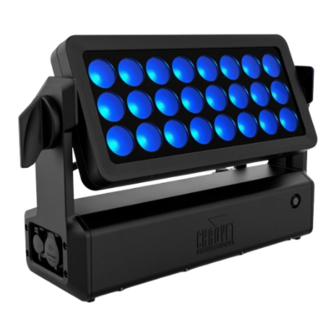
The WELL Panel is a completely wireless, IP65-rated, battery-powered RGBW LED fixture that can be controlled via W-DMX, DMX, or manually from the control panel. The WELL Panel comes with color- blending filter lens for an even diffused light and Omega brackets for easy mounting. Its 170° rotation of the panel from the base allows for easy control of direction of light. -
Page 10: Product Overview
Introduction Product Overview Name Display Menu buttons Power buttons Tilt adjustment knobs DMX out Power out Power in DMX in WELL Panel User Manual Rev. 4... -
Page 11: Product Dimensions
Introduction Product Dimensions 436 mm 17.17 in 159 mm 338 mm 6.26 in 13.3 in 260 mm 10.24 in 88 mm 3.46 in 135 mm 5.31 in WELL Panel User Manual Rev. 4... -
Page 12: Setup
3. Setup AC Power Each WELL Panel has an auto-ranging power supply, and it can work with an input voltage range of 100 to 240 VAC, 50/60 Hz. To determine the product’s power requirements (circuit breaker, power outlet, and wiring), use the current value listed on the label affixed to the product’s back panel, or refer to the product’s specifications chart. -
Page 13: Dmx Linking
If the WELL Panel has already been paired with the W-DMX TRX transmitter, the Signal Strength Indicator in the middle of the LCD screen will show the strength of the signal. In this case, the WELL Panel is ready to work in Wireless mode. -
Page 14: Master/Slave Connectivity
Setup Master/Slave Connectivity The Master/Slave mode allows a WELL Panel (the master) to control one or more WELL Panel products (the slaves) without a DMX controller. One WELL Panel becomes the master when running an auto program, or by being in Static mode. -
Page 15: Operation
<DOWN> Navigates downward through the menu list or decreases the numeric value when in a function Control Options Set the WELL Panel starting address in the 001–512 DMX range. This enables control of up to 21 products in the 21-channel personality. -
Page 16: Menu Map
Turns on or off Red Shift (amber LEDs imitate lamp Red Shift when dimming) Master DMX mode (Master) Master/Slave Slave Slave mode Linear dimmer Dimmer Mode Dimmer 1–3 Dimming curves Dimmer 1 (fast) to Dimmer 3 (slow) WELL Panel User Manual Rev. 4... - Page 17 Shows total hours the product has been powered on Hours Information Version <V_._> Shows current firmware version <_ _ _ _ _ _> Shows product UID Factory Reset Resets the product to factory default settings WELL Panel User Manual Rev. 4...
-
Page 18: Dmx Configuration
026 050 3200K 051 075 3500K 076 100 4000K 101 125 4500K 126 150 5000K 151 175 5600K 176 200 6000K 201 225 6500K 226 255 WELL Panel User Manual Rev. 4... -
Page 19: Dmx Values
Dark amber Amber Light amber Dark pink Pink Light pink No color pink No color blue Light blue Cornflower blue Light pale blue WELL Panel User Manual Rev. 4... - Page 20 Dimmer speed mode off – – – Dimmer speed mode Dimmer speed mode 1 (fastest) Dimmer speed mode 2 Dimmer speed mode 3 (slowest) No function – – Red shift WELL Panel User Manual Rev. 4...
-
Page 21: Standalone Configuration
3. Select from No (disables Red Shift function) or Yes (enables Red Shift function). Dimmer Profiles This setting determines how fast the output of the WELL Panel changes when you modify the output value. This setting provides four different options to simulate the dimming curve of an incandescent lighting product. -
Page 22: Line Voltage Power Loss Mode
8 hours) and 12 Hours (extends battery to the maximum run time of 12 hours) Back Light This setting allows for selection of the amount of time the back light on the WELL Panel’s display stays on after the last button is pressed on the control panel. -
Page 23: Maintenance
17.3592 1.44654 1.9614 Top Frame 17.3592 1.44654 1.9614 Vacuum Test Measurements Use the IP Tester from Chauvet Professional to ensure the product has been reassembled correctly by following the information below: Parameters Values Method Positive Test pressure 40 kPa Test duration... -
Page 24: Technical Specifications
Maximum External Temperature Cooling System 113 °F (45 °C) Convection I/O Connector Channel Range Wireless 4, 8, 12, 13, or 21 channels Ordering Product Name Item Name Item Code UPC Number WELL Panel WELLPANEL 03031717 781462220655 WELL Panel User Manual Rev. 4... -
Page 25: Contact Us
For warranty terms and conditions and return information, please visit our website. For customers in the United States and Mexico: www.chauvetlighting.com/warranty-registration. For customers in the United Kingdom, Republic of Ireland, Belgium, the Netherlands, Luxembourg, France, and Germany: www.chauvetlighting.eu/warranty-registration. WELL Panel User Manual Rev. 4...
Need help?
Do you have a question about the Well Panel and is the answer not in the manual?
Questions and answers