
Related Manuals for protech SE-8134


Summary of Contents for protech SE-8134
- Page 1 USER MANUAL SE-8134 Intel Atom x7/ Celeron ® ® Processor Slim and Fanless Embedded PC SE-8134 M2...
- Page 2 ® (SE-8134) Intel Atom ® Celeron Processor Slim and Fanless Embedded PC COPYRIGHT NOTICE & TRADEMARK All trademarks and registered trademarks mentioned herein are the property of their respective owners. This manual is copyrighted in Apr. 2023. You may not reproduce or transmit in any form or by any means, electronic, or mechanical, including photocopying and recording.
- Page 3 FCC NOTICE This equipment has been tested and found to comply with the limits for a Class A digital device, pursuant to part 15 of the FCC Rules. These limits are designed to provide reasonable protection against harmful interference when the equipment is operated in a commercial environment.
-
Page 4: Table Of Contents
Contents Revision History ..................... v Introduction ..................1-1 About This Manual ..............1-2 Getting Started ..................2-1 Package List ................2-2 System Overview ..............2-3 2.2.1 Front View ................. 2-3 2.2.2 Rear View ................2-3 2.2.3 Top View ................2-3 2.2.4 Side View ................ - Page 5 3.4.4 Power Button Connector ..........3-11 3.4.5 LAN1, LAN2 Ports ............3-12 3.4.6 Dual USB 3.0 Connectors ..........3-14 3.4.7 USB 3.0 Connectors ............3-15 3.4.8 Digital Input/Output Connector ........3-16 3.4.9 I2C Wafer ................. 3-17 3.4.10 I2C PIN2 Voltage Selection ..........3-18 3.4.11 DVI Port ................
- Page 6 4.3.1 Introduction ................ 4-4 4.3.2 Installation Instructions for Windows 10 ......4-4 ® Intel Patch Driver installation ........... 4-5 4.4.1 Introduction ................ 4-5 4.4.2 Installation Instructions for Windows 10 ......4-5 Installing Graphics Driver Utility ..........4-6 Installing LAN Driver Utility ............4-7 Installing Sound Driver Utility ............
- Page 7 Boot ..................5-39 Save & Exit ................5-41 Appendix A System Diagrams ............1 SE-8134 Bottom Cover Exploded Diagram ............2 Heat Sink Exploded Diagram ................3 Front & Rear I/O Panel Installation Exploded Diagram ........4 Mother Board Exploded Diagram ............... 5 HDD Module Exploded Diagram ................
-
Page 8: Revision History
Revision History The revision history of SE-8134 User Manual is described below: Version No. Revision History Page No. Date Revised the picture of System Main Board. 2023/04/07 Corrected DIO1 connector pictures. 3-16 Initial Release 2017/07... -
Page 9: Introduction
Introduction This chapter provides the introduction for the SE-8134 system as well as the framework of the user manual. The following topic is included: • About This Manual SE-8134 SERIES USER MANUAL Page: 1-1... -
Page 10: About This Manual
Chapter 1 Introduction About This Manual Thank you for purchasing our SE-8134 system. The SE-8134 is an updated system designed to be comparable with the highest performance of IBM AT personal computers. The SE-8134 provides faster processing speed, greater expandability and can handle more tasks than before. -
Page 11: Getting Started
Getting Started This chapter provides the information for the SE-8134 system. It describes how to set up the system quickly and outlines the system specifications. The following topics are included: • Package List • System Overview • System Specification • Safety Precautions Experienced users can go to Chapter 3 System Configuration on page 3-1 for a quick start. -
Page 12: Package List
Chapter 2 Getting Started Package List If you discover any of the items listed below are damaged or lost, please contact your local distributor immediately. Item Part No. Q’ty SE-8134 Manual Driver DVD SE-8134 SERIES USER MANUAL Page: 2-2... -
Page 13: System Overview
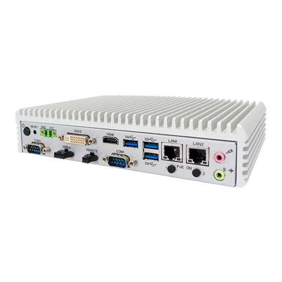
Chapter 2 Getting Started System Overview Unit: mm 2.2.1 Front View 2.2.2 Rear View 2.2.3 Top View SE-8134 SERIES USER MANUAL Page: 2-3... -
Page 14: Side View
Chapter 2 Getting Started 2.2.4 Side View 2.2.5 Quarter View SE-8134 SERIES USER MANUAL Page: 2-4... -
Page 15: System Specifications
COM1/2 for RS232/422/485 selectable by BIOS, Serial Port RI/5V/12V selectable by jumper 2 x LANs with PoE (IEEE 802.3af) as option, Wake-On-LAN, PXE ® ® LAN 1: Intel I210IT / LAN 2 : Intel I210IT SE-8134 SERIES USER MANUAL Page: 2-5... - Page 16 (with airflow) Wide Range Temp. : 0°C ~ 50°C (w/ N3350) Wide Range Temp. : -20°C ~ 50°C (w/ E3950) -40°C ~ 80°C (-40°F ~ 176°F) Storage Temperature 20%~ 90% Humidity SE-8134 SERIES USER MANUAL Page: 2-6...
-
Page 17: Safety Precautions
Avoid direct sunlight exposure for a long period of time (for example, in a closed car in summer time. Also avoid the system from any heating device.). Or do not use SE-8134 when it has been left outdoors in a cold winter day. •... -
Page 18: System Configuration
& connector settings, and component locations for the main board. The following topics are included: • Connector & Jumper Quick Reference Table • System Main Board Component Locations • How to Set Jumpers • Setting Main Board Connectors and Jumpers SE-8134 SERIES USER MANUAL Page: 3-1... -
Page 19: Jumper & Connector Quick Reference Table
Mini PCI Express Slot M_PCIE1 Mini-Serial ATA (SATA) Slot mSATA1 SATA 3.0 Connectors SATA1 HDD Power Connector SATA_PWR1 I2C Wafer JI2C1, JI2C2 Low Pin Count (LPC) Connector JLPC1 Power over Ethernet (PoE) Connector JPOE1 SE-8134 SERIES USER MANUAL Page: 3-2... -
Page 20: Component Locations Of System Main Board
Make sure both the system and peripheral devices are turned OFF as sudden surge of power could damage sensitive components. Make sure SE-8134 is properly grounded. SE-8134 SERIES USER MANUAL Page: 3-3... - Page 21 CAUTION: Always touch the motherboard components by the edges. Never touch components such as a processor by its pins. Take special cares while you are holding electronic circuit boards by the edges only. Do not touch the mainboard components. SE-8134 SERIES USER MANUAL Page: 3-4...
-
Page 22: Bottom View Of System Main Board
Chapter 3 Hardware Configuration 3.2.2 Bottom View of System Main Board Figure 3-2 Main Board Component Location (Rear View) SE-8134 SERIES USER MANUAL Page: 3-5... -
Page 23: How To Set Jumpers
2 to create one setting and shorting. You can also select to connect pins 2 and 3 to create another setting. The format of the jumper picture will be illustrated throughout this manual. The figure below shows different types of jumpers and jumper settings. SE-8134 SERIES USER MANUAL Page: 3-6... - Page 24 Chapter 3 Hardware Configuration Jumper diagrams Jumper settings SE-8134 SERIES USER MANUAL Page: 3-7...
-
Page 25: Setting Main Board Connectors And Jumpers
COM1 and COM2 pin 9 are selectable for RI, +5V or +12V by jumper setting. Default setting is RI, please see “COM1 and COM2 PIN9 Definition Selection Guide” for selection details COM1,COM2 is selectable as RS232, RS422, RS485 by BIOS. SE-8134 SERIES USER MANUAL Page: 3-8... - Page 26 Chapter 3 Hardware Configuration COM3(RS232) Connector Pin Assignment: ASSIGNMENT ASSIGNMENT COM3_DCD COM3_DSR COM3_RX COM3_RTS COM3_TX COM3_CTS COM3_DTR COM3_RI_ COM3/ COM4 COM4(RS232) Connector Pin Assignment: ASSIGNMENT ASSIGNMENT COM4_DCD COM4_DSR COM4_RX COM4_RTS COM4_TX COM4_CTS COM4_DTR COM4_RI_ SE-8134 SERIES USER MANUAL Page: 3-9...
-
Page 27: Com1 And Com2 Pin9 Definition Selection Guide
COM1 and COM2 PIN9 Definition Selection Guide Jumper Name: JP_COM1, JP_COM2 Description: COM1 (JP_COM1) and COM2 pin9 (JP_COM2) RI/5V/12V Selection SELECTION JUMPER SETTING JUMPER ILLUSTRATION (Default Setting) JP_COM1 JP_COM2 +12V JP_COM1 JP_COM2 JP_COM1 JP_COM2 SE-8134 SERIES USER MANUAL Page: 3-10... -
Page 28: Power Input Connector
Chapter 3 Hardware Configuration 3.4.3 Power Input Connector Connector Location: CN_POWER1 Description: Power Input Connector ASSIGNMENT WIDE_POWERIN CN_POWER1 3.4.4 Power Button Connector Connector Location: J_PBTN1 Description: Power Button Connector ASSIGNMENT PWRBTNJ J_PBTN1 SE-8134 SERIES USER MANUAL Page: 3-11... -
Page 29: Lan1, Lan2 Ports
Description: LAN1, LAN2 Port, LAN RJ-45 Port (Rear I/O) LAN1 Pin Assignment: ASSIGNMENT LAN1_MDIP0 LAN1_MDIN0 LAN1_MDIP1 LAN1_MDIP2 LAN1_MDIN2 LAN1_MDIN1 LAN1_MDIP3 LAN1_MDIN3 LAN1 / LAN2 LAN2 Pin Assignment: ASSIGNMENT LAN2_MDIP0 LAN2_MDIN0 LAN2_MDIP1 LAN2_MDIP2 LAN2_MDIN2 LAN2_MDIN1 LAN2_MDIP3 LAN2_MDIN3 SE-8134 SERIES USER MANUAL Page: 3-12... - Page 30 Left Side LED Green Color On7 10/100Mbps LAN Speed Indicator Orange Color On8 Giga LAN Speed Indicator No LAN Switch/HUB connect Right Side LED Yellow Color Blinking LAN Message Active No LAN Message Active SE-8134 SERIES USER MANUAL Page: 3-13...
-
Page 31: Dual Usb 3.0 Connectors
Chapter 3 Hardware Configuration 3.4.6 Dual USB 3.0 Connectors Connector Location: USB1 Description: Dual USB 3.0 Connectors USB 3.0 signals: ASSIGNMENT ASSIGNMENT VCC5_USB1 USB3_RXN1 USB2_P1_DN USB3_RXP1 USB2_P1_DP USB3_TXN1 USB3_TXP1 VCC5_USB1 USB3_RXN2 USB2_P2_DN USB3_RXP2 USB2_P2_DP USB1 USB3_TXN2 USB3_TXP2 SE-8134 SERIES USER MANUAL Page: 3-14... -
Page 32: Usb 3.0 Connectors
Connector Location: USB2, USB3 Description: USB 3.0 Connectors USB 3.0 (USB2) signals: ASSIGNMENT ASSIGNMENT VCC5_USB2 USB3_RXN3 USB2_P3_DN USB3_RXP3 USB2_P3_DP USB3_TXN3 USB3_TXP3 USB2/ USB3 USB 3.0 (USB3) signals: ASSIGNMENT ASSIGNMENT VCC5_USB3 USB3_RXN4 USB2_P4_DN USB3_RXP4 USB2_P4_DP USB3_TXN4 USB3_TXP4 SE-8134 SERIES USER MANUAL Page: 3-15... -
Page 33: Digital Input/Output Connector
Description: Digital Input/Output Connector ASSIGNMENT ASSIGNMENT VCC5 DIN0 DOUT0 DIN1 DOUT1 DIN2 DOUT2 DIN3 DOUT3 JDIO1 System 15 pins DIO Port Pin Assignment: ASSIGNMENT DIN0 DIN1 DIO1 DIN2 VCC_DIO DIN3 DOUT0 DOUT1 DOUT2 DOUT3 SE-8134 SERIES USER MANUAL Page: 3-16... -
Page 34: I2C Wafer
Chapter 3 Hardware Configuration 3.4.9 I2C Wafer Connector Location: JI2C1, JI2C2 Description: I2C Wafer JI2C1 Pin Assignment: ASSIGNMENT V3P3S/VCC5 I2C4_SCL_33 I2C4_SDA_33 JI2C2 Pin Assignment: ASSIGNMENT V3P3S/VCC5 I2C5_SCL_33 JI2C1/ I2C5_SDA_33 JI2C2 SE-8134 SERIES USER MANUAL Page: 3-17... -
Page 35: I2C Pin2 Voltage Selection
JI2C2 pin2: 5V JP_I2C1 Note 1: Users can change the voltage setting according to the connected I2C device. Note 2: Please refer to I2C WAFER for more details about pin definition of JI2C1 and JI2C2. SE-8134 SERIES USER MANUAL Page: 3-18... -
Page 36: Dvi Port
Chapter 3 Hardware Configuration 3.4.11 DVI Port Connector Location: DVI1 Description: DVI (Digital Visual Interface) Connector DVI1 ASSIGNMENT ASSIGNMENT DP0_DVI_N2 DP0_DVI_P2 VCC5_DVI CRT_CLK DP0_DVI_HPD_IN DP0_DVI_N0 DP0_DVI_SCL DP0_DVI_P0 DP0_DVI_SDA DP0_DVI_N1 DP0_DVI_P1 DP0_DVI_CLKP DP0_DVI_CLKN SE-8134 SERIES USER MANUAL Page: 3-19... -
Page 37: Hdmi Port Connector
HDMI Connector (HDMI1) signals: ASSIGNMENT ASSIGNMENT DP1_HDMI_P2 DP1_HDMI_N2 DP1_HDMI_P1 DP1_HDMI_N1 DP1_HDMI_P0- DP1_HDMI_N0 DP1_HDMI_CLKP DP1_HDMI_CLKN DP1_HDMI_SCL DP1_HDMI_SDA VCC5_HDMI DP1_HDMI_HPD_IN HDMI Connector (HDMI2) signals: ASSIGNMENT ASSIGNMENT HDMI_P2 HDMI_N2 HDMI_P1 HDMI_N1 HDMI_P0 HDMI_N0 HDMI_CLKP HDMI_CLKN HDMI_SCL HDMI_SDA V5_HDMI HDMI_HPD SE-8134 SERIES USER MANUAL Page: 3-20... -
Page 38: Hdmi Audio Connector
Chapter 3 Hardware Configuration 3.4.13 HDMI Audio Connector Connector Location: AUDIO1 Description: HD Audio Connector for Line_out/Mic_in ASSIGNMENT HD_MIC1-L HD_GND HD_GND MIC1-JD HD_MIC1-R LINE-OUT-L HD_GND FRONT-JD LINE-OUT-R AUDIO1 SE-8134 SERIES USER MANUAL Page: 3-21... -
Page 39: Low Pin Count (Lpc) Connector
LPC_AD3 LPC_AD2 V3P3A LPC_AD1 JLPC1 Power over Ethernet (PoE) Connector 3.4.15 Connector Location: JPOE1 Description: Power over Ethernet (PoE) Connector ASSIGNMENT ASSIGNMENT OUT2 POE_DATA OUT1 VOUT_54 POE_CLK VOUT_54 PoE_POWERIN VOUT_54 PoE_POWERIN PoE_POWERIN PoE_POWERIN JPOE1 SE-8134 SERIES USER MANUAL Page: 3-22... -
Page 40: Hdmi2 Selection
HDMI2 SELECTION Connector Location: JP_EDP1, JP8 Description: Jumper for selecting JP_EDP1, JP8 of HDMI2 JP_EDP1 signals: SELECTION JUMPER SETTING JUMPER ILLUSTRATION HDMI (Default Setting) JP_EDP1 JP8 signals: SELECTION JUMPER SETTING JUMPER ILLUSTRATION HDMI (Default Setting) SE-8134 SERIES USER MANUAL Page: 3-23... -
Page 41: Mini Pci Express Slot
Mini PCI Express is the successor of the Mini PCI card and provides an increased data throughput. The cards have a detached network interface and are equipped with one lane. They are used in particular in embedded designs or compact box PCs. SE-8134 SERIES USER MANUAL Page: 3-24... -
Page 42: Mini- Serial Ata (Sata) Slot
Mini- Serial ATA (SATA) SLOT Connector Location: mSATA1 Description: Mini-Serial ATA (SATA) Slot ASSIGNMENT ASSIGNMENT V3P3S_MSATA SIM2_PWR SIM2_DATA SIM2_CLK SIM2_RESET SIM2_VPP SIM2_SW2 SIM2_SW1 SATA_RXP1 V3P3S_MSATA SATA_RXN1 mSATA1 SATA_TXN1 SATA_TXP1 USB2_P0_DN USB2_P0_DP V3P3S_MSATA V3P3S_MSATA V3P3S_MSATA SE-8134 SERIES USER MANUAL Page: 3-25... -
Page 43: Serial Ata (Sata) 3.0 Connector
Serial ATA (SATA) 3.0 Connector 3.4.19 Connector Location: SATA1 Description: Serial ATA (SATA) 3.0 Connector ASSIGNMENT SATA_TXP0 SATA_TXN0 SATA_RXN0 SATA1 SATA_RXP0 HDD Power Connector 3.4.20 Connector Location: SATA_PWR1 Description: HDD Power Connector ASSIGNMENT VCC5 SATA_PWR1 SE-8134 SERIES USER MANUAL Page: 3-26... -
Page 44: At / Atx Mode Selection
Description: AT / ATX Mode Selection SELECTION JUMPER SETTING JUMPER ILLUSTRATION Open (Default Setting) JP_ATX1 JP_ATX1 TPM Module Selection 3.4.22 Connector Location: JP_TPM1 Description: TPM Module Selection SELECTION JUMPER SETTING JUMPER ILLUSTRATION Normal (Default Setting) JP_TPM1 Enable JP_TPM1 SE-8134 SERIES USER MANUAL Page: 3-27... -
Page 45: Clear Cmos Data Selection
Step4. Power on the PC and the PC will then auto-reboot for once in order to set SoC’s register. Step5. Done! SELECTION JUMPER SETTING JUMPER ILLUSTRATION Open Normal (Default Setting) Clear CMOS* Note: Please make sure the main power is off before clearing CMOS. SE-8134 SERIES USER MANUAL Page: 3-28... -
Page 46: Software Utilities
Trusted Execution Engine Driver installation • Installing Intel ® Patch Driver installation • Installing Graphics Driver Utility • Installing LAN Driver Utility • Installing Sound Driver Utility • Installing Intel ® Serial I/O Driver Utility SE-8134 SERIES USER MANUAL Page: 4-1... -
Page 47: Introduction
Chapter 4 Software Utilities Introduction Enclosed with the SE-8134 Series package is our driver utilities contained in a DVD-ROM disk. Refer to the following table for driver locations: Filename Purpose (Assume that DVD-ROM drive is D:) ® D:\Driver\Platform\Win10 Intel Chipset Software Installation... -
Page 48: Installing Intel Chipset Software Installation Utility
10 series, and it should be installed immediately after the OS installation is finished. Please follow the steps below: Connect the USB DVD-ROM device to SE-8134 and insert the driver disk. Enter the Main Chip folder where the Chipset driver is located (e.g.: \ Chipset_10.1.1.38\ SetupChipset.exe). -
Page 49: Intel ® Trusted Execution Engine Driver
Installation Instructions for Windows 10 1. Insert the driver disk into a DVD ROM device. 2. Under Windows system, go to the directory where the driver is located. 3. Run the application with administrative privileges. Page: 4-4 SE-8134 SERIES USER MANUAL... -
Page 50: Intel ® Patch Driver Installation
To install the utility, simply follow the following steps: 1. Insert the driver disk into a DVD ROM device. 2. Under Windows system, go to the directory where the driver is located. 3. Run the application with administrative privileges. SE-8134 SERIES USER MANUAL Page: 4-5... -
Page 51: Installing Graphics Driver Utility
Chapter 4 Software Utilities Installing Graphics Driver Utility The GRAPHICS interface embedded in SE-8134 can support a wide range of display types. You can have dual displays via LVDS interfaces and make the system work simultaneously. To install the Graphics driver utility, follow the steps below: Connect the USB DVD-ROM device to SE-8134 and insert the driver disk. -
Page 52: Installing Lan Driver Utility
Installing LAN Driver Utility Enhanced with LAN function, SE-8134 supports various network adapters. To install the LAN Driver, follow the steps below: Connect the USB DVD-ROM device to SE-8134 and insert the driver disk. Enter the LAN folder where the driver is located (depending on your OS platform). -
Page 53: Installing Sound Driver Utility
® Windows 10 series. To install the Sound Driver, follow the steps below: Connect the USB DVD-ROM device to SE-8134 and insert the driver disk. Open the Sound folder where the driver is located (depending on your OS platform). Click the Audio_0008-64bit_Win7_Win8_Win81_Win10_R281.exe file... -
Page 54: Installing Intel Serial I/O Driver Utility
Installing Intel Serial I/O Driver Utility To install the Serial I/O Driver, follow the steps below: Connect the USB DVD-ROM device to SE-8134 and insert the driver disk. Open the Serial I/O folder where the driver is located. Select Windows 10 (64-bit) for your OS platform. -
Page 55: Bios Setup
The BIOS Setup Utilities consist of the following menu items: • Accessing Setup Utilities • Main Menu • Advanced Menu • Chipset Menu • Security Menu • Boot Menu • Save & Exit Menu SE-8134 SERIES USER MANUAL Page: 5-1... -
Page 56: Introduction
Chapter 5 BIOS Setup Introduction The SE-8134 System uses an AMI (American Megatrends Incorporated) Aptio BIOS that is stored in the Serial Peripheral Interface Flash Memory (SPI Flash) and can be updated. The SPI Flash contains the built-in BIOS setup program, Power-On Self-Test (POST), PCI auto-configuration utility, LAN EEPROM information, and Plug and Play support. - Page 57 BIOS setup menu by pressing <Del> or <Esc> immediately while the POST message is running before the operating system is loading. All the menu settings are described in details in this chapter. SE-8134 SERIES USER MANUAL Page: 5-3...
-
Page 58: Accessing Setup Utility
Self-Test (POST) routines and the POST message will be displayed: Figure 5-2. POST Screen with AMI Logo Press <Del> or <Esc> to access the Setup Utility program and the Main menu of the Aptio Setup Utility will appear on the screen as below: SE-8134 SERIES USER MANUAL Page: 5-4... - Page 59 US English. You may use <↑> or <↓> key to select among the items and press <Enter> to confirm and enter the sub-menu. The following table provides the list of the navigation keys that you can use while operating the BIOS setup menu. SE-8134 SERIES USER MANUAL Page: 5-5...
- Page 60 The CMOS battery The battery may be losing power and users is bad or has been should replace the battery immediately. Also, recently replaced. this message is displayed once the new battery is replaced. SE-8134 SERIES USER MANUAL Page: 5-6...
-
Page 61: Main
No changeable options Displays the date that the current BIOS Time version is built. BXT SOC No changeable options Displays the SoC stepping. Displays the current TXE firmware TXE FW No changeable options version. SE-8134 SERIES USER MANUAL Page: 5-7... - Page 62 The “Day” is automatically changed. Sets the system time. The format is [Hour: Minute: Second]. Users can directly enter System Time hour, minute, second values or use <+> or <-> arrow keys to increase/decrease it. SE-8134 SERIES USER MANUAL Page: 5-8...
-
Page 63: Advanced
Sub-Menu CPU Configuration Parameters. F81946 Super IO Sub-Menu F81946 Super IO Chip Parameters. Configuration Network Stack Sub-Menu Network Stack Settings Configuration USB Configuration Sub-Menu USB Configuration Parameters. Platform Trust Sub-Menu Platform Trust Technology Technology SE-8134 SERIES USER MANUAL Page: 5-9... -
Page 64: Advanced - Acpi Settings
SUSPEND button is - Suspend Disabled pressed. If S3 (Suspend to RAM) is ACPI Sleep State - S3 (Suspend to RAM) selected, the system shuts down with the exception of a refresh current to the memory. SE-8134 SERIES USER MANUAL Page: 5-10... -
Page 65: Advanced - Hardware Monitor
No changeable options Detects and displays 3V voltage. VSB3V No changeable options Detects and displays VSB3V voltage. No changeable options Detects and displays VSB5V voltage. VSB5V Detects and displays the battery VBAT No changeable options voltage. SE-8134 SERIES USER MANUAL Page: 5-11... -
Page 66: Advanced - F81946 Watchdog Configuration
Selects 1s (second) or 60s (minute) as Watchdog Timer Unit - 60s the time unit of Watchdog timer. Watchdog Timer Numeric Sets the timeout for Watchdog timer. Count (from 1 to 255) (Max. value: 255 seconds or minutes) SE-8134 SERIES USER MANUAL Page: 5-12... -
Page 67: Advanced - Cpu Configuration
Intel Virtualization - Disabled provided by Vanderpool Technology. Technology - Enabled Previously codenamed "Vanderpool", VT-x represents Intel’s technology for virtualization on the x86 platform. VT-d - Disabled settings. Enable or Disable VT-d - Enabled SE-8134 SERIES USER MANUAL Page: 5-13... - Page 68 Hyper Threading is Intel’s term for its simultaneous Reports if Intel VT-x Technology is supported by processor. Previously Intel VT-x Technology No changeable options codenamed "Vanderpool", VT-x represents Intel’s technology for virtualization on the x86 platform. SE-8134 SERIES USER MANUAL Page: 5-14...
- Page 69 Displays L1 Data Cache Size L1 Code Cache No changeable options Displays L1 Code Cache Size L2 Cache No changeable options Displays L2 Cache Size L3 Cache No changeable options Displays L3 Cache Size SE-8134 SERIES USER MANUAL Page: 5-15...
- Page 70 Advanced - CPU Configuration - CPU Power Management Menu Path Advanced > CPU Configuration> CPU Power Management CPU Power Management Screen BIOS Setting Options Description/Purpose - Disabled EIST Enable or Disable Intel SpeedStep. - Enabled SE-8134 SERIES USER MANUAL Page: 5-16...
-
Page 71: Advanced - F81946 Super Io Configuration
Sets the parameters of Serial Port 2 Serial Port 2 Configuration Sub-menu (COMB). Sets the parameters of Serial Port 3 Serial Port 3 Configuration Sub-menu (COMC). Sets the parameters of Serial Port 4 Serial Port 4 Configuration Sub-menu (COMD). SE-8134 SERIES USER MANUAL Page: 5-17... - Page 72 Allows you to select specific - IO=3F8h; IRQ=3,4,5,6,7,10,11; Change Settings IO address and IRQ for Serial - IO=2F8h; IRQ=3,4,5,6,7,10,11; Port 1. - IO=3E8h; IRQ=3,4,5,6,7,10,11; - IO=2E8h; IRQ=3,4,5,6,7,10,11; - RS-232 Mode - RS-422 Selects COM mode. - RS-485 SE-8134 SERIES USER MANUAL Page: 5-18...
- Page 73 Allows you to select specific - IO=3F8h; IRQ=3,4,5,6,7,10,11; Change Settings IO address and IRQ for Serial - IO=2F8h; IRQ=3,4,5,6,7,10,11; Port 2. - IO=3E8h; IRQ=3,4,5,6,7,10,11; - IO=2E8h; IRQ=3,4,5,6,7,10,11; - RS-232 Mode - RS-422 Selects COM mode. - RS-485 SE-8134 SERIES USER MANUAL Page: 5-19...
- Page 74 Serial Port 3. - Auto - IO=3E8h; IRQ=7; Allows you to select specific - IO=3E8h; IRQ=3,4,5,6,7,10,11; Change Settings IO address and IRQ for Serial - IO=2E8h; IRQ=3,4,5,6,7,10,11; Port 3. - IO=2F0h; IRQ=3,4,5,6,7,10,11; - IO=2E0h; IRQ=3,4,5,6,7,10,11; SE-8134 SERIES USER MANUAL Page: 5-20...
- Page 75 Serial Port 4. - Auto - IO=2E8h; IRQ=10; Allows you to select specific - IO=3E8h; IRQ=3,4,5,6,7,10,11; Change Settings IO address and IRQ for Serial - IO=2E8h; IRQ=3,4,5,6,7,10,11; Port 4. - IO=2F0h; IRQ=3,4,5,6,7,10,11; - IO=2E0h; IRQ=3,4,5,6,7,10,11; SE-8134 SERIES USER MANUAL Page: 5-21...
-
Page 76: Advanced - Network Stack Configuration
Number of seconds to wait for PXE boot to PXE boot wait time (from 0 to 5) abort after the Esc key is pressed. Numeric Number of times that the media presence Media detect count (from 1 to 50) will be checked. SE-8134 SERIES USER MANUAL Page: 5-22... -
Page 77: Advanced - Usb Configuration
The USB Configuration allows users to configure advanced USB settings such as USB mass storage driver support. USB Configuration Screen BIOS Setting Options Description/Purpose USB Mass Storage - Disabled Enables or Disables USB Mass Storage Driver Support - Enabled Driver Support. SE-8134 SERIES USER MANUAL Page: 5-23... -
Page 78: Advanced - Platform Trust Technology
The Platform Trust Technology allows users to configure advanced TPM settings such as fTPM. Platform Trust Technology Screen BIOS Setting Options Description/Purpose Enables or Disables fTPM. - Disabled fTPM It must be disabled when discrete TPM is - Enabled used. SE-8134 SERIES USER MANUAL Page: 5-24... -
Page 79: Chipset
This menu allows users to configure advanced Chipset settings such as North Bridge and South Bridge configuration parameters.. Chipset Screen BIOS Setting Options Description/Purpose North Bridge Sub-menu North Bridge Parameters. South Bridge Sub-menu South Bridge Parameters. SE-8134 SERIES USER MANUAL Page: 5-25... -
Page 80: Chipset -North Bridge
Displays the current amount and type of Total Memory No changeable options memory on the system, e.g. "2048 MB". Displays the current size of SO-DIMM#1 SO-DIMM#1 No changeable options on the system, e.g. "2048 MB". SE-8134 SERIES USER MANUAL Page: 5-26... -
Page 81: Chipset -South Bridge
Description/Purpose HD-Audio Configuration Sub-menu HD-Audio Configuration Settings LPSS Configuration Sub-menu LPSS Configuration Settings. PCI Express Configuration Sub-menu PCI Express Configuration Settings. SATA Drives Sub-menu SATA Device Configuration Settings. Miscellaneous Configurations Sub-menu Miscellaneous Configurations Settings. SE-8134 SERIES USER MANUAL Page: 5-27... -
Page 82: Chipset -South Bridge- Hd-Audio Configuration
Chapter 5 BIOS Setup Chipset –South Bridge- HD-Audio Configuration 5.5.2.1 Menu Path Chipset > South Bridge > HD-Audio Configuration HD-Audio Configuration Screen BIOS Setting Options Description/Purpose - Disabled Enables or Disables HD-Audio HD-Audio Configuration - Enabled support. SE-8134 SERIES USER MANUAL Page: 5-28... -
Page 83: Chipset -South Bridge- Lpss Configuration
- High Speed Mode - Disabled I2C2 Support Enables or Disables I2C2 Support. - Enabled - Standard Mode - Fast Mode Set I2C2 Speed Selects I2C2 Speed. - Fast Plus Mode - High Speed Mode SE-8134 SERIES USER MANUAL Page: 5-29... -
Page 84: Chipset -South Bridge- Pci Express Configuration
PCI Express Root Port 0 (LAN 1) Sub-menu (LAN 1) parameters.. PCI Express Root Port 1 PCI Express Root Port 1 (LAN 2) Sub-menu (LAN 2) parameters. Mini PCI Express Port 1 Sub-menu Mini PCI Express Port 1 parameters. SE-8134 SERIES USER MANUAL Page: 5-30... - Page 85 Port automatically for saving PCI Express Root Port 0 - Enabled the most optimum power. (LAN 1) -Auto (default) Enable: Enable PCI Express Root Port 0 (LAN 1). Disable: Disable PCI Express Root Port 0 (LAN 1). SE-8134 SERIES USER MANUAL Page: 5-31...
- Page 86 PCI Express Root Port 1 - Enabled the most optimum power. (LAN 2) - Auto (default) Enable: Enable PCI Express Root Port 1 (LAN 2). Disable: Disable PCI Express Root Port 1 (LAN 2). SE-8134 SERIES USER MANUAL Page: 5-32...
- Page 87 - Disabled - L0s PCI Express Active State Power ASPM - L1 Management settings. - L0sL1 - Auto - Disabled - L1.1 L1 Substates PCI Express L1 Substates settings. - L1.2 - L1.1 & L1.2 SE-8134 SERIES USER MANUAL Page: 5-33...
- Page 88 Chapter 5 BIOS Setup - Disabled Enables or Disables PCI Express Hot Hot Plug - Enabled Plug. - Auto PCIe Speed - Gen1 Selects PCI Express Port Speed. - Gen2 SE-8134 SERIES USER MANUAL Page: 5-34...
-
Page 89: Chipset -South Bridge- Sata Drives
Enables or Disables SATA Port 1 - Enabled Display mSATA drive branding mSATA Port 1 No changeable options information if device exists on mSATA Port 1 - Disabled Port 1 Enables or Disables mSATA Port 1 - Enabled SE-8134 SERIES USER MANUAL Page: 5-35... -
Page 90: Chipset -South Bridge- Miscellaneous Configuration
- S5 State as soon as power applied. • S5 State: System keeps in power-off state until power button is pressed. - Disabled Enables or Disables the Wake on Lan Wake On Lan - Enabled (WOL). SE-8134 SERIES USER MANUAL Page: 5-36... -
Page 91: Security
Setup utility. Security Screen BIOS Setting Options Description/Purpose Setup Administrator Password can be 3-20 Specifies the administrator password. Password alphanumeric characters. Password can be 3-20 User Password Specifies the user password. alphanumeric characters. SE-8134 SERIES USER MANUAL Page: 5-37... - Page 92 Security menu and press <Enter>, and the password dialog entry box appears. 2. Select the configured Administrator Password or User Password that you want to delete. Leave the dialog box blank and press <Enter>. 3. Press <Enter> again when the password confirmation box appears. SE-8134 SERIES USER MANUAL Page: 5-38...
-
Page 93: Boot
• On: Enables the NumLock function Bootup - On automatically after the system is NumLock State - Off powered on. • Off: Disables the NumLock function after the system is powered on. SE-8134 SERIES USER MANUAL Page: 5-39... - Page 94 Allows users to change the boot order from the available device(s). Boot Option - [Drive(s)] Note that in the menu displayed, you will #1~#n - Disabled only see the device with the highest priority for a specific boot device type. SE-8134 SERIES USER MANUAL Page: 5-40...
-
Page 95: Save & Exit
Discard Changes and Reset to discard any changes you have made and restore the factory BIOS defaults. Load User Defaults You may simply press F3 at any time to load the Optimized Values which resets all BIOS settings to the factory defaults. Save & Exit Screen SE-8134 SERIES USER MANUAL Page: 5-41... - Page 96 Saves the changes done so far as User No changeable options Defaults Defaults. Restore User Restores the User Defaults to all the BIOS No changeable options Defaults settings. Forces to boot the system from selected Boot Override - [Drive(s)] [drive(s)]. SE-8134 SERIES USER MANUAL Page: 5-42...
-
Page 97: Appendix A System Diagrams
This appendix includes the exploded diagrams of the system and the parts list as well as the part numbers of the SE-8134 system. • SE-8134 Bottom Cover Exploded Diagram • Heat Sink Exploded Diagram • Front & Rear I/O Panel Installation Exploded Diagram •... -
Page 98: Se-8134 Bottom Cover Exploded Diagram
Appendix A System Diagrams SE-8134 Bottom Cover Exploded Diagram Q’ty Component Name Part No. Silver 20-004-03062401 Bottom Cover (w/Paint) Blue 20-004-03061401 Rubber Foot (Φ 11.1x3.96mm)(Black) 90-004-01400000 Flat Head Screw-M4 x0.7Px6mm(Black) 22-215-40006011 Flat Head Screw#2/M3x0.5Px5mm 22-215-30005011 SE-8134 SERIES USER MANUAL Page: A-2... -
Page 99: Heat Sink Exploded Diagram
Choke Thermal Pad (15x15x1.0mm) 81-006-81515007 CPU Thermal Pad (13x13x1mm) 81-006-81313003 22-215-30004011 Flat Head Screw M3x0.5Px4mm(Black) LAN Thermal Pad (10x10x4.0mm) 81-006-81010005 Audio Thermal Pad (7x7x3.5mm) 81-006-80707001 PCH Thermal Pad (15x15x3.0mm) 81-006-81515006 Fillister Head Screw#2/M3x0.5Px5mm 22-272-30049015 SE-8134 SERIES USER MANUAL Page: A-3... -
Page 100: Front & Rear I/O Panel Installation Exploded Diagram
PoE LED Cable L=75mm (GREEN) 27-018-40102071 Hole Plug (Φ 6.6mm) (Black) 90-067-01100000 HEX CU Boss UNC No.4-40, L=4.8, H=7mm 22-692-40048051 HEX Boss(NI) M3x0.5Px4.5L, H=28.5mm 22-252-30029901 Flat Head Screw M3x0.5Px4mm (Black) 22-215-30004011 30-001-28100099 Switch Expanding Cover SE-8134 SERIES USER MANUAL Page: A-4... -
Page 101: Mother Board Exploded Diagram
Appendix A System Diagrams Mother Board Exploded Diagram Q’ty Component Name Part No. Black Heat Sink Assembly Silver SB-8134 M/B PoE Board SR-8134RB-D0N HEX Boss(NI) M3x0.5Px6L,H=24.7mm 22-252-30025901 Fillister Head Screw #1/M2x0.4Px4mm 22-272-20004011 Flat Head Screw #2/M3x0.5Px5mm 22-215-30005001 SE-8134 SERIES USER MANUAL Page: A-5... -
Page 102: Hdd Module Exploded Diagram
HDD Cable Holder Asm 20-029-03001401 HDD Support Bracket 20-006-03001401 HDD Cable Flat Head Screw #2/M3x0.5Px5mm 22-215-30005011 Fillister Head Screw #2/M3x0.5Px5mm 22-272-30049015 Fillister Head Screw M3x0.5Px4.8mm 82-272-30005013 Rubber Washer 23-680-39580963 (OD=φ 9.62mm,ID=φ 3.9mmx5.8T) EMI Shielding Gasket (10x3x17mm) 30-050-31700000 SE-8134 SERIES USER MANUAL Page: A-6... -
Page 103: Packing Exploded Diagram
Silica Gel 1gm 34-005-00010007 Outer Carton (280x146x267mm) 94-001-01301205 Outer Carton (310x290x290mm) 34-001-01401205 Accessories Box 234X155X45mm for PS8830X with Compact Stand (1): Q’ty Component Name Part No. Mini Jumper 2.0mm 10-611-00200023 CD Driver Quick Manual SE-8134 SERIES USER MANUAL Page: A-7... -
Page 104: Appendix B Technical Summary
This appendix will give you a brief introduction of the allocation maps for the system resources. The following topics are included: • System Block Diagram • Interrupt Map • I/O Map • Memory Map • Configuring WatchDog Timer • Flash BIOS Update Page: B-1 SE-8134 SERIES USER MANUAL... - Page 105 Appendix B Technical Summary System Block Diagram SE-8134 SERIES USER MANUAL Page: B-2...
-
Page 106: Interrupt Map
IRQ 63 Microsoft ACPI-Compliant System IRQ 64 Microsoft ACPI-Compliant System IRQ 65 Microsoft ACPI-Compliant System IRQ 66 Microsoft ACPI-Compliant System IRQ 67 Microsoft ACPI-Compliant System IRQ 68 Microsoft ACPI-Compliant System IRQ 69 Microsoft ACPI-Compliant System SE-8134 SERIES USER MANUAL Page: B-3... - Page 107 IRQ 93 Microsoft ACPI-Compliant System IRQ 94 Microsoft ACPI-Compliant System IRQ 95 Microsoft ACPI-Compliant System IRQ 96 Microsoft ACPI-Compliant System IRQ 97 Microsoft ACPI-Compliant System IRQ 98 Microsoft ACPI-Compliant System IRQ 99 Microsoft ACPI-Compliant System SE-8134 SERIES USER MANUAL Page: B-4...
- Page 108 IRQ 123 Microsoft ACPI-Compliant System IRQ 124 Microsoft ACPI-Compliant System IRQ 125 Microsoft ACPI-Compliant System IRQ 126 Microsoft ACPI-Compliant System IRQ 127 Microsoft ACPI-Compliant System IRQ 128 Microsoft ACPI-Compliant System IRQ 129 Microsoft ACPI-Compliant System SE-8134 SERIES USER MANUAL Page: B-5...
- Page 109 IRQ 153 Microsoft ACPI-Compliant System IRQ 154 Microsoft ACPI-Compliant System IRQ 155 Microsoft ACPI-Compliant System IRQ 156 Microsoft ACPI-Compliant System IRQ 157 Microsoft ACPI-Compliant System IRQ 158 Microsoft ACPI-Compliant System IRQ 159 Microsoft ACPI-Compliant System SE-8134 SERIES USER MANUAL Page: B-6...
- Page 110 IRQ 183 Microsoft ACPI-Compliant System IRQ 184 Microsoft ACPI-Compliant System IRQ 185 Microsoft ACPI-Compliant System IRQ 186 Microsoft ACPI-Compliant System IRQ 187 Microsoft ACPI-Compliant System IRQ 188 Microsoft ACPI-Compliant System IRQ 189 Microsoft ACPI-Compliant System SE-8134 SERIES USER MANUAL Page: B-7...
- Page 111 IRQ 264 Microsoft ACPI-Compliant System IRQ 265 Microsoft ACPI-Compliant System IRQ 266 Microsoft ACPI-Compliant System IRQ 267 Microsoft ACPI-Compliant System IRQ 268 Microsoft ACPI-Compliant System IRQ 269 Microsoft ACPI-Compliant System IRQ 270 Microsoft ACPI-Compliant System SE-8134 SERIES USER MANUAL Page: B-8...
- Page 112 IRQ 294 Microsoft ACPI-Compliant System IRQ 295 Microsoft ACPI-Compliant System IRQ 296 Microsoft ACPI-Compliant System IRQ 297 Microsoft ACPI-Compliant System IRQ 298 Microsoft ACPI-Compliant System IRQ 299 Microsoft ACPI-Compliant System IRQ 300 Microsoft ACPI-Compliant System SE-8134 SERIES USER MANUAL Page: B-9...
- Page 113 IRQ 324 Microsoft ACPI-Compliant System IRQ 325 Microsoft ACPI-Compliant System IRQ 326 Microsoft ACPI-Compliant System IRQ 327 Microsoft ACPI-Compliant System IRQ 328 Microsoft ACPI-Compliant System IRQ 329 Microsoft ACPI-Compliant System IRQ 330 Microsoft ACPI-Compliant System SE-8134 SERIES USER MANUAL Page: B-10...
- Page 114 IRQ 354 Microsoft ACPI-Compliant System IRQ 355 Microsoft ACPI-Compliant System IRQ 356 Microsoft ACPI-Compliant System IRQ 357 Microsoft ACPI-Compliant System IRQ 358 Microsoft ACPI-Compliant System IRQ 359 Microsoft ACPI-Compliant System IRQ 360 Microsoft ACPI-Compliant System SE-8134 SERIES USER MANUAL Page: B-11...
- Page 115 IRQ 384 Microsoft ACPI-Compliant System IRQ 385 Microsoft ACPI-Compliant System IRQ 386 Microsoft ACPI-Compliant System IRQ 387 Microsoft ACPI-Compliant System IRQ 388 Microsoft ACPI-Compliant System IRQ 389 Microsoft ACPI-Compliant System IRQ 390 Microsoft ACPI-Compliant System SE-8134 SERIES USER MANUAL Page: B-12...
- Page 116 IRQ 414 Microsoft ACPI-Compliant System IRQ 415 Microsoft ACPI-Compliant System IRQ 416 Microsoft ACPI-Compliant System IRQ 417 Microsoft ACPI-Compliant System IRQ 418 Microsoft ACPI-Compliant System IRQ 419 Microsoft ACPI-Compliant System IRQ 420 Microsoft ACPI-Compliant System SE-8134 SERIES USER MANUAL Page: B-13...
- Page 117 IRQ 444 Microsoft ACPI-Compliant System IRQ 445 Microsoft ACPI-Compliant System IRQ 446 Microsoft ACPI-Compliant System IRQ 447 Microsoft ACPI-Compliant System IRQ 448 Microsoft ACPI-Compliant System IRQ 449 Microsoft ACPI-Compliant System IRQ 450 Microsoft ACPI-Compliant System SE-8134 SERIES USER MANUAL Page: B-14...
- Page 118 IRQ 474 Microsoft ACPI-Compliant System IRQ 475 Microsoft ACPI-Compliant System IRQ 476 Microsoft ACPI-Compliant System IRQ 477 Microsoft ACPI-Compliant System IRQ 478 Microsoft ACPI-Compliant System IRQ 479 Microsoft ACPI-Compliant System IRQ 480 Microsoft ACPI-Compliant System SE-8134 SERIES USER MANUAL Page: B-15...
- Page 119 IRQ 504 Microsoft ACPI-Compliant System IRQ 505 Microsoft ACPI-Compliant System IRQ 506 Microsoft ACPI-Compliant System IRQ 507 Microsoft ACPI-Compliant System IRQ 508 Microsoft ACPI-Compliant System IRQ 509 Microsoft ACPI-Compliant System IRQ 510 Microsoft ACPI-Compliant System SE-8134 SERIES USER MANUAL Page: B-16...
- Page 120 IRQ 4294967291 Intel(R) Trusted Execution Engine Interface IRQ 4294967292 Standard SATA AHCI Controller Intel(R) Celeron(R)/Pentium(R) Processor PCI IRQ 4294967293 Express Root Port - 5AD9 Intel(R) Celeron(R)/Pentium(R) Processor PCI IRQ 4294967294 Express Root Port - 5AD8 SE-8134 SERIES USER MANUAL Page: B-17...
-
Page 121: I/O Map
Motherboard resources Intel(R) Celeron(R)/Pentium(R) 0x0000F040-0x0000F05F Processor SMBUS - 5AD4 Intel(R) Celeron(R)/Pentium(R) 0x0000D000-0x0000DFFF Processor PCI Express Root Port - 5AD9 0x000003F8-0x000003FF Communications Port (COM1) 0x000002F8-0x000002FF Communications Port (COM2) 0x000003E8-0x000003EF Communications Port (COM3) 0x000002E8-0x000002EF Communications Port (COM4) SE-8134 SERIES USER MANUAL Page: B-18... - Page 122 Programmable interrupt controller 0x000000B8-0x000000B9 Programmable interrupt controller 0x000000BC-0x000000BD Programmable interrupt controller 0x000004D0-0x000004D1 Programmable interrupt controller 0x0000F090-0x0000F097 Standard SATA AHCI Controller 0x0000F080-0x0000F083 Standard SATA AHCI Controller 0x0000F060-0x0000F07F Standard SATA AHCI Controller 0x00000040-0x00000043 System timer 0x00000050-0x00000053 System timer SE-8134 SERIES USER MANUAL Page: B-19...
-
Page 123: Memory Map
5AD9 Intel(R) Serial IO I2C Host 0x9131C000-0x9131CFFF Controller - 5AB4 Intel(R) Serial IO I2C Host 0x9131B000-0x9131BFFF Controller - 5AB4 0xFED00000-0xFED003FF High precision event timer Intel(R) USB 3.0 eXtensible Host 0x91300000-0x9130FFFF Controller - 1.0 (Microsoft) SE-8134 SERIES USER MANUAL Page: B-20... - Page 124 0xCFFFE000-0xCFFFEFFF Intel SD Host Controller 0x91314000-0x91315FFF Standard SATA AHCI Controller 0x9131E000-0x9131E0FF Standard SATA AHCI Controller 0x9131D000-0x9131D7FF Standard SATA AHCI Controller Intel(R) I210 Gigabit Network 0x91280000-0x912FFFFF Connection #2 Intel(R) I210 Gigabit Network 0x9127C000-0x9127FFFF Connection #2 SE-8134 SERIES USER MANUAL Page: B-21...
-
Page 125: Configuring Watchdog Timer
To exit the Extended Function Mode, writing 0xAA to the EFER is required. Once the chip exits the Extended Function Mode, it is in the normal running mode and is ready to enter the configuration mode. SE-8134 SERIES USER MANUAL Page: B-22... - Page 126 Enable watchdog timer and set timeout interval to 30 seconds. ; --------------------Enter to extended function mode------------------------- ; -----------------Select Logical Device 7 of watchdog timer---------------- ;-------------------------Enable Watch dog feature----------------------------- 030h ;------------------------------Enable Watch PME-------------------------------- 0FAh ; -------------------------Set timeout interval to 30----------------------------- 0F6h SE-8134 SERIES USER MANUAL Page: B-23...
- Page 127 Appendix B Technical Summary ;--------------Set second as counting unit and start counting --------------- 0F5h ;----------------------Exit the extended function mode--------------------- 0AAh SE-8134 SERIES USER MANUAL Page: B-24...
-
Page 128: Flash Bios Update
(3) The system will go into the BIOS setup menu. (4) Select [Boot] menu. (5) Select [UEFI: Built-in EFI Shell] as the 1 boot device. (6) Press F4 to save the configuration and exit the BIOS setup menu. SE-8134 SERIES USER MANUAL Page: B-25... - Page 129 BIOS ROM may be crashed and the system will be unable to boot up next time. After the BIOS update procedure is completed, the following messages will be shown: SE-8134 SERIES USER MANUAL Page: B-26...
- Page 130 5. Restart the system and boot up with the new BIOS configurations. 6. The BIOS Update is completed after the system is restarted. 7. Reboot the system and verify if the BIOS version shown on the initialization screen has been updated. SE-8134 SERIES USER MANUAL Page: B-27...
Need help?
Do you have a question about the SE-8134 and is the answer not in the manual?
Questions and answers