
Subscribe to Our Youtube Channel
Related Manuals for protech EB-471


Summary of Contents for protech EB-471
- Page 1 USER’S MANUAL EB-471 ULV Celeron ® 3.5” Embedded Card With VGA/ SOUND/ LAN EB-471 M3...
- Page 2 Copyright Notice EB-471 Celeron® M 3.5” Embedded Card With VGA /Sound/LAN OPERATION MANUAL COPYRIGHT NOTICE This operation manual is meant to assist both Embedded Computer manufacturers and end users in installing and setting up the system. The information contained in this document is subject to change without any notice.
- Page 3 Copyright Notice FCC NOTICE This equipment has been tested and found to comply with the limits for a Class A digital device, pursuant to part 15 of the FCC Rules. These limits are designed to provide reasonable protection against harmful interference when the equipment is operated in a commercial environment.
-
Page 4: Table Of Contents
Contents TABLE OF CONTENTS CHAPTER 1 INTRODUCTION About This Manual ............System Specification ............Safety Precautions ............CHAPTER 2 HARDWARE CONFIGURATION Jumper & Connector Quick Reference Table ....Component Locations ............ How to Set the Jumpers ..........COM Port Connector ……..…………………………... RS232/422/485(COM2) Selection ........ - Page 5 Contents CHAPTER 3 SOFTWARE UTILITIES Introduction …………..........…..VGA Driver Utility ……………………………….…… Flash BIOS Update ..........…..LAN Driver Utility …...........…..Sound Driver Utility …………………………………… Intel Chipset Software Installation Utility …..……..….. USB2.0 Software Installation Utility ………………….. Watchdog Timer Configuration ……………………….. 3-10 CHAPTER 4 AWARD BIOS SETUP Introduction ..............
-
Page 6: Chapter 1 Introduction
CHAPTER INTRODUCTION This chapter gives you the information for EB-471. It also outlines the System specification. Section includes: About This Manual System Specifications Safety precautions Experienced users can skip to chapter 2 on page 2-1 for Quick Start. Page:1-1... -
Page 7: About This Manual
Chapter 1 Introduction 1-1. ABOUT THIS MANUAL Thank you for purchasing our EB-471 Celeron® M3.5” Embedded Card enhanced with VGA /Sound/ LAN, which is fully PC / AT compatible. EB- 471 provides faster processing speed, greater expandability and can handle more task than before. -
Page 8: System Specification
PS/2 keyboard with mini DIN connector or one external Y cable. UNIVERSAL SERIAL BUS : Universal Serial Bus Connector on board Supports up to two USB 2.0 ports. BUS SUPPORT : PC/104+ Connector. ′ Page: 1-3 EB-471 USER S MANUAL... - Page 9 One 5-pin Infrared connector Supports IrDA v1.0 SIR protocol. LED INDICATOR : HDD LED, Power LED. DMA CONTROLLER : 82C37 x 2 DMA CHANNELS : INTERRUPT CONTROLLERS : 82C59 x 2 INTERRUPT LEVELS : ′ Page: 1-4 EB-471 USER S MANUAL...
-
Page 10: Safety Precautions
3. Disconnect power when you change any hardware devices. For instance, when you connect a jumper or install any cards, a surge of power may damage the electronic components or the whole system. ′ Page: 1-5 EB-471 USER S MANUAL... -
Page 11: Chapter 2 Hardware Configuration
CHAPTER HARDWARE CONFIGURATION ** QUICK START ** Helpful information describes the jumper & connector settings, and component locations. Section includes: Jumper & Connector Quick Reference Table Component Locations Configuration and Jumper settings Connector’s Pin Assignments Page 2-1... -
Page 12: Jumper & Connector Quick Reference Table
Power Requirement Selection ………………………… AT Power Connector …………….…………………… Inverter Connector ………………………………….… Reset/NMI/Watchdog Selection .…………..………….. LVDS1 LVDS Connector ……………………………………… Panel Voltage Selection …………………………….… Sound Connector ………………………………………. JTV1 TV-Out Connector ………………………………….… LED1 LAN LED ………………………………………………. ′ Page: 2-2 EB-471 USER S MANUAL... -
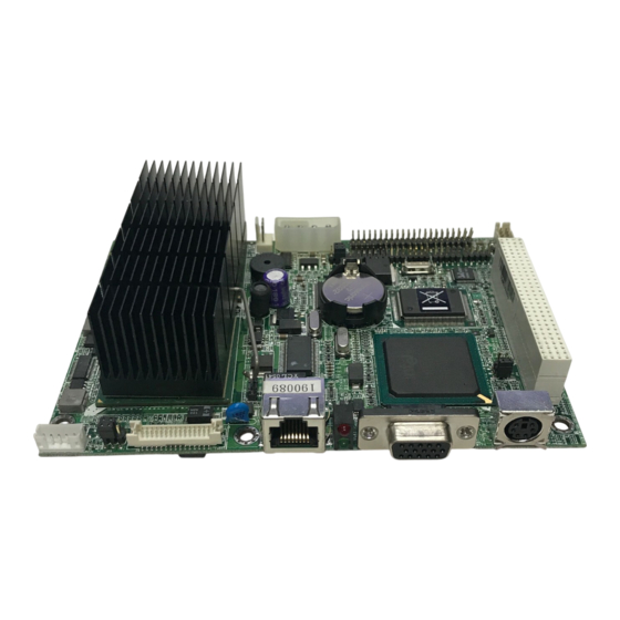
Page 13: Component Locations
Chapter 2 Hardware Configuration 2-2. COMPONENT LOCATIONS VGA1 LVDS1 DIN1 LED1 LAN1 INTEL AC97 JPANEL1 COM1 COM2 Celeron-M JTV1 JSFAN1 IDE1 USB1 EB-471 Connector, Jumper and Component locations ′ Page: 2-3 EB-471 USER S MANUAL... -
Page 14: How To Set The Jumpers
You can connect PIN1 & PIN2 to create one setting and shorting. You can either connect PIN2 & PIN3 to create another setting. The same jumper diagrams are applied all through this manual. The figure below shows what the manual diagrams look and what they represent. ′ Page: 2-4 EB-471 USER S MANUAL... - Page 15 Jumper Block looks like this JUMPER SETTINGS 2 pin Jumper close(enabled) Looks like this 3 pin Jumper 2-3 pin close(enabled) Looks like this Jumper Block 1-2 pin close(enabled) Looks like this ′ Page: 2-5 EB-471 USER S MANUAL...
-
Page 16: Com Port Connector
DSR1 RTS1 CTS1 COM2 : COM2 Connector The COM2 is selectable as RS-232/422/485. The pin assignment is as follows : ASSIGNMENT RS-232 RS-422 RS-485 DCD2 DTR2 DSR2 RTS- RTS2 RTS+ CTS2 CTS+ CTS- ′ Page: 2-6 EB-471 USER S MANUAL... -
Page 17: Rs232/422/485(Com2) Selection
This connector is used to set the COM2 function. The jumper settings are as follows : COM 2 Jumper Settings Jumper Function (pin closed) Illustrations RS-232 Open RS-422 1-2, 3-4, 9-10 RS-485 1-2, 5-6, 7-8 *** Manufactory default --- RS-232. ′ Page: 2-7 EB-471 USER S MANUAL... -
Page 18: Keyboard/Mouse Connector
The pin assignment is as follows : ASSIGNMENT RST_SW 2-8. HARD DISK DRIVE LED CONNECTOR JPANEL (2, 4) : Hard Disk Drive LED Connector The pin assignment is as follows : ASSIGNMENT VCC3_3_R HD_LED ′ Page: 2-8 EB-471 USER S MANUAL... -
Page 19: External Speaker Connector
2-10. POWER LED CONNECTOR JPANEL1 (1, 3) : Power LED Connector The pin assignment is as follows: ASSIGNMENT VCC_R 2-11. IRDA CONNECTOR JIRDA1: IrDA (Infrared) Connector The pin assignments are as follows: ASSIGNMENT IRRX IRTX ′ Page: 2-9 EB-471 USER S MANUAL... -
Page 20: System Fan Connector
JSFAN1 : System Fan connector The pin assignment is as follows: ASSIGNMENT +12V FAN0 2-13. VGA CONNECTOR VGA1 : VGA CRT Connector The pin assignments are as follows: ASSIGNMENT GREEN BLUE VGA_P5V VGA_5VDDCDA VGA_HSYNC_5V VGA_VSYNC_5V VGA_5VDDCLK ′ Page: 2-10 EB-471 USER S MANUAL... -
Page 21: Hard Disk Drive Connector
IDERSTJ PDD7 PDD8 PDD6 PDD9 PDD5 PDD10 PDD4 PDD11 PDD3 PDD12 PDD2 PDD13 PDD1 PDD14 PDD0 PDD15 PDREQ PDIOWJ PDIORJ PIORDY PULL LOW PDDACKJ IRQ14 PDA1 P66 DET PDA0 PDA2 PDCSJ1 PDCSJ3 IDEACTPJ ′ Page: 2-11 EB-471 USER S MANUAL... -
Page 22: Universal Serial Bus Connector
USB1: Universal Serial Bus Connector The pin assignments are as follows: ASSIGNMENT VCCUSB0 USBP0N USBP0P VCCUSB0 USBP1N USBP1P 2-16. LAN CONNECTOR LAN1: LAN Connector The pin assignments are as follows: ASSIGNMENT ISOLATED_GND ISOLATED_GND ISOLATED_GND ISOLATED_GND ′ Page: 2-12 EB-471 USER S MANUAL... -
Page 23: Clear Cmos Data Selection
Note: To clear CMOS data, user must power-off the computer and set the jumper to “Clear CMOS” as illustrated above. After five to six seconds, set the jumper back to “Normal” and power-on the computer. ′ Page: 2-13 EB-471 USER S MANUAL... -
Page 24: Power Requirement Selection
JP2 : Power Requirement Selection The selections are as follows: JUMPER JUMPER Power Selection SETTINGS ILLUSTRATION (pin closed) +5V & +12V 1-3, 2-4 +5V Only 3-5, 4-6 ** Manufacturing default: +5V & +12V ** ′ Page: 2-14 EB-471 USER S MANUAL... -
Page 25: At Power Connector
Chapter 2 Hardware Configuration 2-19. AT POWER CONNECTOR PW1 : AT Power Connector The pin assignments are as follows: ASSIGNMENT VCC12EX 2-20. INVERTER CONNECTOR J2 : Inverter Connector The pin assignment is as follows: ASSIGNMENT LVDS_BKLTEN ′ Page: 2-15 EB-471 USER S MANUAL... -
Page 26: Reset/Nmi Watchdog Selection
User may select to use the Reset or NMI watchdog. NMI, also known as Non-Maskable Interrupt, is used for serious conditions that demand the processor’s immediate attention, it cannot be ignored by the system unless it is shut off specifically. ′ Page: 2-16 EB-471 USER S MANUAL... -
Page 27: Lvds Connector
Chapter 2 Hardware Configuration 2-22. LVDS CONNECTOR LVDS1 : LVDS Connector. The pin assignments are as follows: ASSIGNMENT ASSIGNMENT LVDS_VCC LVDS_VCC LVDS_VCC ′ Page: 2-17 EB-471 USER S MANUAL... -
Page 28: Panel Voltage Selection
Chapter 2 Hardware Configuration 2-23. PANEL VOLTAGE SELECTION JP5 : Panel Voltage Selection. The selections are as follows: JUMPER SETTING JUMPER SELECTION ILLUSTRATION LVDS_VCC3 1-3, 2-4 LVDS_VCC5 3-5, 4-6 ′ Page: 2-18 EB-471 USER S MANUAL... -
Page 29: Sound Connector
J1 : Sound Connector. The pin assignments are as follows: ASSIGNMENT MIC-IN LINE-L LINE-R SPK-L SPK-R 2-25. TV-OUT CONNECTOR JTV1 : TV-Out Connector. The pin assignments are as follows: ASSIGNMENT TVYFCC2 TVCVB TVCFCC2 ′ Page: 2-19 EB-471 USER S MANUAL... -
Page 30: Lan Led
Chapter 2 Hardware Configuration 2-26. LAN LED LED1 : LAN LED The pin assignments are as follows: ASSIGNMENT ACTLEDJ LILEDJ RJ45VCCA SPLEDJ ′ Page: 2-20 EB-471 USER S MANUAL... - Page 31 CHAPTER SOFTWARE UTILITIES This chapter comprises the detailed information of VGA driver, LAN driver, and Flash BIOS update. It also describes how to install the watchdog timer configuration. Section includes: VGA Driver Utility Flash BIOS Update LAN Driver Utility Sound Driver Utility Intel®...
- Page 32 Chapter 3 Software Configuration 3-1. INTRODUCTION Enclosed with our EB-471 package is our driver utility, which may comes in a form of a CD ROM disc or floppy diskettes. For CD ROM disc user, you will only need some of the files contained in the CD ROM disc, please kindly...
- Page 33 Under the Windows 98 system, after rebut computer, there will have two error messages appear, “Can’t find ikch8xx.cat and isb8xx.cat”, just skip the messages, they will not cause any effects. ′ Page:3-3 EB-471 USER S MANUAL...
- Page 34 Utility Disk for system BIOS and VGA BIOS update. 3-3-2. To update VGA BIOS for LCD Flat Panel Display: As EB-471 user, you have to update the VGA BIOS for your specific LCD flat panel you are going to use. For doing this, you need two files.
- Page 35 File Name to Program: H20bxxxx.bin Checksum: XXXXX Reset System or Power off to accomplish update process! F1: Reset F10: Exit Please reset or power off the system, and then the Flash BIOS is fully implemented. ′ Page:3-5 EB-471 USER S MANUAL...
- Page 36 Chapter 3 Software Configuration 3-4. LAN DRIVER UTILITY 3-4-1. Introduction EB-471 is enhanced with LAN function that can support various network adapters. Installation programs for LAN drivers are listed as follows: Win 98/2000/XP program Linux program For more details on Installation procedure, please refer to Readme.txt file found on LAN DRIVER UTILITY.
- Page 37 “D:\Sound\pathname” refers to the full path to the source files. 3. Click on the OK button or press the ENTER key. 4. Click on the “Next” and OK prompts as they appear. 5. Reboot the system to complete the driver installation. ′ Page:3-7 EB-471 USER S MANUAL...
- Page 38 3. Click Setup.exe file for utility installation. 4. Follow the instructions on the screen to complete the installation. 5. Once installation is completed, shut down the system and restart in order for the changes to take effect. ′ Page:3-8 EB-471 USER S MANUAL...
- Page 39 5. Double Click “USB Root Hub”. 6. Select “Driver”. 7. Click “Install” to install the driver. 8. Follow the instructions on the screen to complete the installation. 9. Click “Finish” after the driver installation is complete. ′ Page:3-9 EB-471 USER S MANUAL...
- Page 40 Example Program 1. Enable watchdog timer and set 30 sec. as timeout interval ;----------------------------------------------------------- Mov dx, 2eh ; Enter to extended function mode Mov al, 87h Out dx, al Out dx, al ;----------------------------------------------------------- ′ Page:3-10 EB-471 USER S MANUAL...
- Page 41 Dec dx ; Set timeout interval as 30seconds and start counting Mov al, 0f6h Out dx,al Inc dx Mov al, 30 Out dx,al ;----------------------------------------------------------- Dec dx ; Exit the extended function mode Mov al, 0aah Out dx,al ′ Page:3-11 EB-471 USER S MANUAL...
- Page 42 CHAPTER AWARD BIOS SETUP This chapter shows how to set up the Award BIOS. Section includes: Introduction Entering Setup The Standard CMOS Features The Advanced BIOS Features The Advanced Chipset Features Integrated Peripherals Power Management Setup PNP/PCI Configuration PC Health Status Frequency Control Load Fail-Safe Defaults Load Optimized Defaults...
- Page 43 4-1. INTRODUCTION This chapter will show you the function of the BIOS in managing the features of your system. The EB-471 M Embedded CPU Card is equipped with the BIOS for system chipset from Award Software Inc. This page briefly explains the function of the BIOS in managing the special features of your system.
- Page 44 You may use the cursor the up/down keys to highlight the individual menu items. As you highlight each item, a brief description of the highlighted selection will appear at the bottom of the screen. ′ Page: 4-3 EB-471 USER S MANUAL...
- Page 45 < Hour >, < Minute >, and < Second >. Use 24 hour clock format, i.e., for PM numbers, add 12 to the hour. For example: 4: 30 P.M. You should enter the time as 16:30:00. ′ Page: 4-4 EB-471 USER S MANUAL...
- Page 46 Auto: The BIOS automatically determines the optimal mode. Normal: Maximum number of cylinders, heads, sectors supported are 1024, 16 and 63. Large: For drives that do not support LBA and have more than 1024 cylinders. ′ Page: 4-5 EB-471 USER S MANUAL...
- Page 47 BASE MEMORY: Displays the amount of conventional memory detected during boot up. EXTENDED MEMORY: Displays the amount of extended memory detected during boot up. TOTAL MEMORY: Displays the total memory available in the system. ′ Page: 4-6 EB-471 USER S MANUAL...
- Page 48 1024 65535 1023 1024 65535 1023 1024 65535 1023 1024 65535 1023 1024 65535 1023 65535 1023 65535 1024 65535 1023 1024 65535 1023 65535 65535 65335 AUTO Award Hard Disk Type Table ′ Page: 4-7 EB-471 USER S MANUAL...
- Page 49 QUICK POWER ON SELF-TEST: This item allows you to speed up Power On Self Test (POST) after power-up the computer. When enabled, the BIOS will shorten or skip some check items during POST. ′ Page: 4-8 EB-471 USER S MANUAL...
- Page 50 Setup freely. OS SELECT FOR DRAM >64MB : Select the operating system that is running with greater than 64MB or RAM on the system. You may choose OS2 or Non-OS2. ′ Page: 4-9 EB-471 USER S MANUAL...
- Page 51 The default settings have been chosen because they provide the best opera- ting conditions for the system. The only time you might consider making any changes would be if you discovered that data was being lost while using your system. ′ Page: 4-10 EB-471 USER S MANUAL...
- Page 52 VIDEO BIOS CACHEABLE: Select Enabled allows caching of the video BIOS, resulting in better system performance. However, if any program writes to this memory area, a system error may result. ′ Page: 4-11 EB-471 USER S MANUAL...
- Page 53 PANEL TYPE: (depend on chipset) This field allows user to decide the LVDS panel resolution. The available choices are: 640x480 18bits, 800x600 18bits, 1024x768 18bits, 1280x1024 36bits, 1400x1050 36bits, 1600x1200 36bits, and 1024x768 24bits. ′ Page: 4-12 EB-471 USER S MANUAL...
- Page 54 If bios setup menu item supports USB device boot, it will cause Win9x detects the same storages twice when the system is rebooted, and USB HDD will fail. Note: this cause just happen under Win9x, the phenomenon is a limitation. ′ Page: 4-13 EB-471 USER S MANUAL...
- Page 55 Ultra DMA/33 implementation is possible only if your IDE hard drive supports it and the operating environment includes a DMA driver (Windows 95 OSR2 or a third-party IDE bus master driver). If you ′ Page: 4-14 EB-471 USER S MANUAL...
- Page 56 USB keyboard. 3. USB Mouse Support Select Enabled if your system contains a Universal Serial Bus (USB) controller and you have a USB Mouse. 4. Init Display First ′ Page: 4-15 EB-471 USER S MANUAL...
- Page 57 This item allows you to select the IR half/full duplex function. 7. Use IR Pins This item allows you to select IR transmission routes, one is RxD2m, TxD2 (COM Port) and the other is IR-Rx2Tx2 ′ Page: 4-16 EB-471 USER S MANUAL...
- Page 58 Enabled, even when the system is in a power down mode. (1) Primary IDE 0 (2) Primary IDE 1 (3) Secondary IDE 0 (4) Secondary IDE 1 (5) FDD, COM, LPT Port ′ Page: 4-17 EB-471 USER S MANUAL...
- Page 59 Normally, you leave this field Disabled. Select Enabled to reset Extended System Configuration Data (ESCD) when you exit Setup if you have installed a new add-on and the system configuration has caused such a serious conflict that the operating system cannot boot. ′ Page: 4-18 EB-471 USER S MANUAL...
- Page 60 F6:Fail-Safe Defaults F7:Optimized Defaults Descriptions on each item above are as follows: 1. IRQ-n Assigned to: You may assign each system interrupt a type, depending on the type of device using the interrupt. ′ Page: 4-19 EB-471 USER S MANUAL...
- Page 61 CURRENT SYSTEM FAN SPEED: This item shows you the current System FAN speed. VCORE: This item shows you the current system voltage. 3.3V / +5V / +12V / VBAT/5VSB: Show you the voltage of 3.3V/+5V/+12V/VBAT/5VSB. ′ Page: 4-20 EB-471 USER S MANUAL...
- Page 62 Enabling pulse spectrum spread modulation changes the extreme values from spikes to flat curves, thus reducing EMI. This benefit may in some cases be outweighed by problems with timing- critical devices such as a clock-sensitive SCSI device. ′ Page: 4-21 EB-471 USER S MANUAL...
- Page 63 When you press <Enter> on this category, you get a confirmation dialog box with a message similar to the following: Load Optimized Defaults ( Y/N ) ? N Pressing "Y" loads the default values that are factory setting for optimal performance system operations. ′ Page: 4-22 EB-471 USER S MANUAL...
- Page 64 PASSWORD DISABLED!!! Press any key to continue... Press the < Enter > key again and the password will be disabled. Once the password is disabled, you can enter Setup freely. ′ Page: 4-23 EB-471 USER S MANUAL...
- Page 65 You may always call up the setup program at any time to adjust any of the individual items by pressing the <Del> key during boot up. ′ Page: 4-24 EB-471 USER S MANUAL...
- Page 66 ►Integrated Peripherals ►Power Management word Quit Without Saving (Y/N)? N ►PnP/PCI Configura etup ►PC Health Status Saving Esc : Quit ↑↓→← : Select Item F10 : Save & Exit Setup Abandon all Datas ′ Page: 4-25 EB-471 USER S MANUAL...
- Page 67 EXPANSION APPENDIX This appendix indicates the pin assignments. Section includes: PC/104 Plus BUS Connector Pin Assignment Page: A-1...
- Page 68 IDSEL2 AD24 C/BE3# V/I/O IDSEL3 AD26 AD25 AD29 AD28 AD27 AD30 AD31 REQ0# REQ1# V/I/O REQ2# GNT0# GNT1# V/I/O GNT2# CLK0 CLK1 CLK2 CLK3 INTD# RST# +12V INTA# INTB# INTC# -12V Reserved Reserved ′ Page: A-2 EB-471 USER S MANUAL...
- Page 69 APPENDIX TECHNICAL SUMMARY This section introduce you the maps concisely. Section includes: Block Diagram Interrupt Map RTC & CMOS RAM Map Timer & DMA Channels Map I / O & Memory Map Page: B-1...
- Page 70 Appendix B Technical Summary BLOCK DIAGRAM ′ Page: B-2 EB-471 USER S MANUAL...
- Page 71 Appendix B Technical Summary INTERRUPT MAP ASSIGNMENT System TIMER Keyboard Cascade Serial port 2 Serial port 1 Available Floppy Parallel port 1 RTC clock Available Available Available PS/2 Mouse Math coprocessor IDE1 IDE2 ′ Page: B-3 EB-471 USER S MANUAL...
- Page 72 Extension memory low byte Extension memory high byte Reserved for extension memory low byte Reserved for extension memory high byte Date Century byte Information Flag 34-3F Reserve 40-7f Reserved for Chipset Setting Data ′ Page: B-4 EB-471 USER S MANUAL...
- Page 73 TIMER & DMA CHANNELS MAP Timer Channel Map : Timer Channel Assignment System timer interrupt DRAM Refresh request Speaker tone generator DMA Channel Map : DMA Channel Assignment Available Available Floppy Available Cascade Available Available Available ′ Page: B-5 EB-471 USER S MANUAL...
- Page 74 Parallel port-2 2B0-2DF Graphics adapter controller 2F8-2FF Serial port-2 360-36F Net work ports 378-37F Parallel port-1 3B0-3BF Monochrome & Printer adapter 3C0-3CF EGA adapter 3D0-3DF CGA adapter 3F0-3F7 Floppy disk controller 3F8-3FF Serial port-1 ′ Page: B-6 EB-471 USER S MANUAL...
Need help?
Do you have a question about the EB-471 and is the answer not in the manual?
Questions and answers