
Related Manuals for Storz MASTERPULS MP200


Summary of Contents for Storz MASTERPULS MP200
- Page 1 MASTERPULS MP200 ® BS.#### Part No. 23220.xxxx Published: May 2016 Original language: German Publisher: STORZ MEDICAL AG Lohstampfestr. 8 CH-8274 Tägerwilen Switzerland 25294...
-
Page 2: Table Of Contents
Table of Contents General Safety Information Instructions for safe use 1.1.1 Designated use and operational safety. 1.1.2 Safety during treatment of the patient. Warning against damage to equipment and the device Principles Physical principles 2.1.1 Indications . 2.1.2 Contraindications . . - Page 3 Operation of the handpiece Operation of the Touch Screen of the Tablet PC 4.4.1 Module selection . . 23 4.4.2 Parameter selection and counter display . . 24 4.4.3 Contact intensity and Skin Touch display . . 26 4.4.4 Treatment menu bar . .
- Page 4 4.10 Treatment with R-SW or V-ACTOR handpiece 4.10.1 Setting parameters . 55 4.10.2 Coupling the handpiece . . 55 4.10.3 Triggering shocks . . 56 4.10.4 Functions overview of the handpiece R-SW . . 56 4.11 Treatment with VACU-ACTOR 4.11.1 Using the foot switch .
- Page 5 Preface Warning notes This manual contains warnings, safety instructions and specific operating instructions in accordance with liability regulations. DANGER refers to a situation of acute danger which, if not avoided, could lead to serious or fatal injury. DANGER! The source of the danger is stated here. These are the possible consequences! •...
-
Page 6: General Safety Information
The device is only allowed to be used for the applications described in C 2.1.1 hapter ndiCatiOns • Only perform treatments approved by STORZ MEDICAL AG! Furthermore, the device is only allowed to be operated by trained personnel who comply with the p in C 2.2. -
Page 7: Safety During Treatment Of The Patient
• Disconnect the connected handpieces from the device before carrying out cleaning and maintenance work. Do not reconnect them until they have been completely reassembled! • The optional KARL STORZ foot switch must not be used in potentially explosive atmospheres according to classification AP as per IEC 60601. Protection against noise The noise level during administration of shock waves is within the safe area. - Page 8 The use of accessories or cables that are not authorised by the manufacturer can result in increased interference emissions or reduced resistance to interference emissions by the device. The MASTERPULS MP200 is not allowed to be positioned immediately next to ®...
-
Page 9: Principles
Principles Physical principles The MASTERPULS MP200 is a compressed air–operated ballistic shock wave genera- ® tor. The shock waves in the MASTERPULS MP200 are generated with a precision ® ballistic mechanism in the handpiece. A projectile is accelerated by compressed air. The motion and weight of the projectile produce kinetic energy. -
Page 10: Contraindications
2.1.2 Contraindications CAUTION! No claims are made regarding the completeness or unlimited validity of this list of contraindications. Treatment with the STORZ MEDICAL MASTERPULS MP200 is not permitted in the ® following cases: – Coagulation disorders (haemophilia) – Use of anticoagulants, especially Marcumar –... -
Page 11: Preconditions For Operation
An introduction to the principles of operation will be provided by your STORZ MEDICAL dealer with reference to this operating manual and will be documented in the system logbook. -
Page 12: System Description
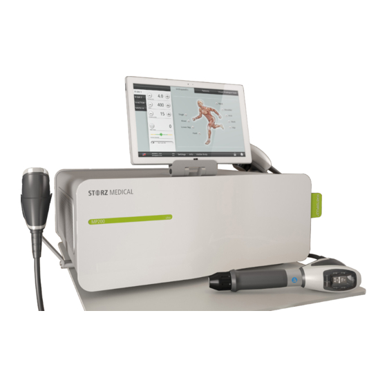
System Description Control and functional elements The MASTERPULS ® MP200 is exclusively controlled using the operating and display elements on the handpiece. 1 Handpiece connector V-ACTOR 2 Handpiece connector R-SW 3 Handpiece connector R-SW 4 Connector VACU-ACTOR Fig. 3-1 Front and right side of MASTERPULS ®... -
Page 13: Scope Of Supply
1 Opening for the nebulizer 2 Openings for handpiece holder Fig. 3-3 Bottom side MASTERPULS MP200 ® Scope of supply The standard scope of supply of the MASTERPULS ® MP200 includes the following items: – MASTERPULS MP200 control device ® –... -
Page 14: Transport
Transport It requires two persons to transport the device after unpacking riskless and safe to the treatment place. NOTE Make sure that your hands are dry and free of grease. • Dismount the handpiece holder before transporting the device. • Grip on the front and on the rear side with both hands on the bottom of the de- vice as shown in in Fig. -
Page 15: Suction Cup Holder
The mounting of the handpiece holder is equal for both types. • Push the holder into the provided openings at the Masterpuls MP200. ® 3.5.1.2 Suction cup holder 1 Openings for insertion of the handpiece and suction cup holder Fig. 3-6 Mounting the suction cup holder •... -
Page 16: Connecting The Potential Equalisation
3.5.3 Connecting the potential equalisation At the rear side of the device a connection of a potential equalisation (Fig. 3-7/2) is available if due to national regulations or room class a connection is required. • Connect the cable for the potential equalisation to the PE connector of the MAS- TERPULS MP200 (Fig. -
Page 17: Connecting Vacu-Actor
1 USB connector for connecting Tablet PC 2 Footswitch connector Fig. 3-10 Connection of tablet and footswitch - MP200 rear side • Connect the USB connector of the tablet into the USB connector on the rear side of the MP200. 3.5.6 Connecting VACU-ACTOR 1 Connection coupling for the... -
Page 18: Connecting The Foot Switch
Treatment with the VACU-ACTOR can be activated and deactivated with the aid of the foot switch. Fig. 3-13 Optional Karl Storz foot switch Compatibility The STORZ MEDICAL Masterpuls MP200 is allowed to be operated with the following handpieces: – handpiece R-SW part.no. 21700_xxxx –... -
Page 19: Symbols
Symbols You must read the operating manual Application unit of type B Potential equalisation Connector R-SW handpiece Connector V-ACTOR handpiece Connector VACU-ACTOR USB-connector CE mark (in accordance with the Medical Device Directive (MDD) 93/42/EEC) CSA test mark WEEE label wearing ear protection 19 600 02 0516... -
Page 20: Operation
Operation Switching on and off • Switch on the device using the main switch on the rear side of the device. 1 main switch Fig. 4-1 Main switch Operation The following options for operating the MP200 are available: – MP200 with R-SW handpiece –... - Page 21 Operation of the handpiece This device can be controlled directly using the handpiece. Corresponding setting buttons can be used for selecting the treatment parameters. The indicator window shows which setting has been selected. 1 decrease energy 2 increase energy 3 decrease frequency 4 increase frequency 5 Trigger button 6 Display energy...
- Page 22 Operation of the Touch Screen of the Tablet PC When using the handpiece R-SW handpiece or V-ACTOR handpiece as well as the VACU-ACTOR the MP200 can also be controlled by a colour TFT monitor with touch screen function. This allows individual adjustment of the parameters for the V-ACTOR handpiece as well as the VACU-ACTOR.
- Page 23 4.4.1 Module selection The field at the top left is used for displaying the operating modes that can be se- lected. Once a handpiece or the VACU-ACTOR is connected, it is possible to activate the corresponding operating mode in the mode selection area. The active module button is highlighted.
- Page 24 4.4.2 Parameter selection and counter display The PARAMETER SELECTION field is used for displaying and setting the treatment parameters. Operating mode R-SW Here you define the energy level as well as the number and frequency of the pulses before each treatment. Fig.
- Page 25 Operating mode VACU-ACTOR Fig. 4-6 Setting parameters- operating mode VACU-ACTOR Symbols Meaning Set intensity: decrease / reduce It can be selected from 1 to 5. Set time limit: decrease / reduce The set time limit is displayed. Set nominal frequency: decrease / reduce The set frequency is displayed.
- Page 26 Explanation of terms Mode VI The suction cup creates an interaction of vacuum and positive pressure with the adju- sted frequency. Mode VC The suction cup creates a negative pressure. It pulsates between vacuum and ventila- tion by different frequency settings. Sizes of suction cups Size XS Size S...
- Page 27 For this purpose consider the following notes: CAUTION! Danger of injury from inadvertent shock triggering Trigger shocks only when the handpiece is in contact with the in- tended treatment zone. Avoid accidental contact between the patient and the handpiece when the Skin Touch function is activated. •...
- Page 28 4.4.4 Treatment menu bar Use the TREATMENT menu bar to call up stored treatment parameters and treatment reports as indications. Fig. 4-8 Treatment menu bar Buttons Meaning Markers for various The ANATOMY view appears automatically when the treatment zones device is started. Press the corresponding markers to call up factory-set or user-defined indications for the various treatment zones.
- Page 29 4.4.5 Device info and settings menu bar The bottom navigation bar contains control buttons used for navigating through the menus: – Software update – Options – Service VERSIONS – Serial number and indices of the individual components OPERATING DATA – Total pulse count and device operating hours (depending on operating mode selected) –...
- Page 30 Touch screen operation 4.5.1 Configuration and reset When starting the tablet the first time the touchscreen displays the content shown in Fig. 4-9. While the first connection of the tablet to the device the tablet will be confi- gured automatically for this device. Fig.
- Page 31 Fig. 4-11 Reset system configuration • Confirm „Reset system configuration?“ by pressing – The tablet will now be resetted and all stored patient and treatment data will be deleted. • Now start the tablet anew. 4.5.2 Password protection It is possible to protect your SMAG tablet with a password. If starting the tablet anew or if it is in screen saver mode so the display is locked and can only be unlocked by entering the password.
- Page 32 Fig. 4-13 Password entry • Confirm with h Your password is activated. Deactivate password protection • Press several seconds on date and time field • Press to deactivate password entry (the check mark needs to be can- celled after that). •...
- Page 33 4.5.3 Setting brightness and volume • Select • Select in the open top menu bar. Fig. 4-15 Options • Tap on the scale at the desired position in order to adjust the brightness of the screen or the volume. • Press to save the settings.
- Page 34 The operating mode is exited if you – select another mode – load an indication which requires working in another mode – operate another handpiece 4.5.5 Selecting treatment parameters You can set the treatment parameters manually or load a predefined indication. For manual selection •...
- Page 35 To load only the indications for a particular treatment zone • Press the marker for the treatment zone. Fig. 4-18 Selectable treatment zones – The alphabetically sorted list of indications for this treatment zone is opened. Navigating in the list Use the navigation bar on the right edge of the display to move within the list.
- Page 36 Fig. 4-20 Overview - information about stored indications Calling up detailed views: For increased clarity, you can call up magnified views of the treatment photos as well as the recommended shock transmitters and stand-off devices. • Press the corresponding treatment photo. –...
- Page 37 Fig. 4-22 D20 detailed view Use the buttons to switch to the display of the previous or next element. • Press to switch to the treatment step overview. Loading treatment steps • Load the first treatment step using the button in front of it. –...
- Page 38 Loading a patient dataset You can now call up a patient record directly from the loaded indication. • Press – The list of stored patient data is opened. • Load the required dataset by pressing – The name of the patient is displayed in the status bar with the loaded indication.
- Page 39 • Use the onscreen keypad to enter an indication name and treatment region. • Save your entry by pressing • Create a treatment .step (see C 4.5.10.3). hapter • Save your entry by pressing NOTE An empty indication without any entryof a treatment step will not be saved. h Your indication is now created in the system.
- Page 40 4.5.9 Deleting an indication • Press – The list of indications is displayed. • Select the indication that you want to delete by pressing the button in front of – The indication is opened. DELETE INDICATION. • Press • Confirm your input by pressing NOTE This only applies to your own indications.
- Page 41 4.5.10.1 Storing treatment notes • To add remarks to the indication, press in the line. Using the onscreen keypad, you can now enter your remarks and notes in the text box. • Save your text by pressing h The text appears in the overview window of the indication. 4.5.10.2 Loading images and/or videos Not only images but also videos can be loaded in WMV format.
- Page 42 Deleting pictures and/or videos • To remove a picture or a video from the picture line, press on the symbol in the picture and confirm your entry with h The picture or video is deleted from the indication. 4.5.10.3 Creating, deleting or editing treatment steps •...
- Page 43 4.5.11 Patient treatment report Each treatment of a patient can be recorded in a treatment report and stored. 4.5.11.1 Loading patient data • Press in the top menu bar. – The alphabetically sorted list of patient data is opened. Fig. 4-31 List of stored patient data Navigating in the list Use the navigation bar on the right edge of the display to move within the list.
- Page 44 Fig. 4-32 Patient data • In the TREATMENTS line, press the button to call up details. – You can now see which parameters have been used for the patient’s treat- ment. Fig. 4-33 Treatment parameters used 19 600 02 0516...
- Page 45 4.5.11.2 Editing patient data You can add additional notes or treatment pictures by setting the dataset to editing mode. • Press the button to do this. The buttons with the pencil icon indicate the areas that can be edited. You can now: –...
- Page 46 4.5.12 Creating new patient data • Press in the top menu bar. – The alphabetically sorted list of patients is opened. • Press – A window with a keypad and text boxes for the patient data is opened. Fig. 4-35 Creating a new patient •...
- Page 47 4.5.13 Exporting treatment data This function can be used to export treatment data to a USB memory stick as Excel-readable files. • Ensure that your USB stick supports the USB V1.1 protocol. You can order a validated USB stick from your dealer. •...
- Page 48 4.5.16 Software updates 4.5.16.1 Software Update Tablet PC • Before performing software update download the update. • Extract the files. • Load the extracted files onto an USB stick. • Connect the USB stick to the USB connector of the tablet PC. •...
- Page 49 4.5.17 Changing software settings This function enables you to activate or deactivate indication groups. • Press • In the open menu list, select the function. Fig. 4-37 Options: Orthopaedics active You see the list of possible indication groups. symbol before an indication group indicates that it is activated. •...
- Page 50 4.5.18.1 Starting Visible Body • To start Anatomy Atlas, press Fig. 4-38 Visible Body - Main menu Fig. 4-39 Visible Body - Selection of the muscle region 19 600 02 0516...
- Page 51 4.5.18.2 Marking treatment regions • To load the marking pencil, press Fig. 4-40 Visible Body - Marking the treatment region • Now draw your markings of the region on the control panel. Fig. 4-41 Visible Body - Marked region • Press the symbol to create a screenshot.
- Page 52 4.5.18.3 Exiting Visible Body • To exit the program, press on a module selection field (R-SW) or the empty area located below on the left that is outside the Visible Body screen. Fig. 4-42 Exit Visible Body Setting treatment parameters •...
- Page 53 Start-up • Set the energy of the shocks to an initial value of 2 bar. The maximum pressure is limited to 5.0 bar. The minimum pressure that can be set is 1.0 bar. The R-SW handpiece can be operated in single shock mode and in continuous shock mode.
- Page 54 Standard settings • Before each treatment, make sure that the shock wave counter is set to zero. NOTE Set the nominal value counter to the required value. R-SW • Start the R-SW treatment at a pressure of 2 bar and a frequency of 5 Hz. V-ACTOR •...
- Page 55 CAUTION! Malfunction of the device or its components Various injuries are possible! • Immediately comply with all status and error messages which appear during the treatment (see Operating Manual of the handpiece). CAUTION! Over extended periods, the noise of the shocks can be per- ceived as unpleasant! •...
- Page 56 4.10.3 Triggering shocks Once all necessary preparations have been taken, it is possible to start the treatment. • Make sure that the shock wave counter is at zero and a low energy level has been set. • Press the trigger button on the handpiece. –...
- Page 57 4.11.1 Using the foot switch When using the foot switch to activate the VACU-ACTOR the treatment is carried out with intensity 3. The treatment will always be carried out with mode VI in which alternately an under- pressure and overpressure will be produced. •...
- Page 58 Cleaning, Maintenance, Overhaul Cleaning Regular cleaning of the system ensures perfect hygiene and operation of the Masterpuls ® MP200. CAUTION! Electrical hazard! Disconnect the device and the accessories from the mains before starting any cleaning and overhauling work! Overall external cleaning depends on the frequency of use and application of the device.
- Page 59 5.1.2.1 Preparation of cleaning Choose a clean, dust-free workplace, to perform the cleaning and disinfection. Material required Make sure that the following objects and tools for cleaning and disinfection are available: – clean, soft and and lint-free cleaning tissues – cleaning agent suitable for polycarbonate –...
- Page 60 ATTENTION ! Avoid damaging the suction cup ! Sharp tools, abrasive or strongly alkaline detergents, solvents, leaded benzine and carbon tetrachloride should not be used. All mechanical cleaning systems for example brushes are not allowed. Corrosive cleaning agents and sharp devices are not allowed. ATTENTION ! The suction cup consists of polycarbonate.
- Page 61 Maintenance services can be ordered from our regional representatives in your area or directly from STORZ MEDICAL AG. Independently of the national accident prevention regulations and test and inspection intervals prescribed for medical devices, we recommend that functional checks (see 4.8 f...
- Page 62 Repair work on defective devices must only be carried out by personnel suitably authorised by STORZ MEDICAL. Only original STORZ MEDICAL spare parts may be used for this purpose. The personnel suitably authorised can be from STORZ MEDICAL or be representatives of STORZ MEDICAL agencies and dealers.
- Page 63 Accessories Mains cable CEE 4 m long 13455 Mains cable CH 3 m long 13448 R-SW »Falcon« handpiece set 21700.1001 R-SW »Falcon« overhaul kit 26894 A6 shock transmitter 17675 T10 shock transmitter set 13457 R15 shock transmitter 17638 C15 shock transmitter 19222 F15 shock transmitter 21356...
- Page 64 Technical Specifications Technical Specifications MASTERPULS MP200 ® single shock, continuous shock R-SW operating mode HP 21700.0001: 1-21 Hz / 1-5 bar in steps of 0.1 bar HP 21700.1001: 1-21 Hz / 0.3-5 bar operating mode V-ACTOR: - standard 31 Hz / 2,4 bar - when using an 1 - 35 Hz / 1 - 5 bar external display...
- Page 65 Equipment safety (“essential performance“) according to IEC 60601-1, 3rd edition: Applied acoustic energy does not exceed the specified limit of 6.5 bar with a tolerance of 10%. The applied underpressure with the suction cup is limited to -500 mbar. NOTE When the medical product is distributed to third parties, the following must be observed: –...
- Page 66 Conformity with standards No. 601.1, This device complies with the applicable standards EN 60601-1, CAN / CSA-C22.2 UL Std. No. 60601-1. Acc. to EN 60601-1 - Type of protection against electric shocks: Protection class 1 - Application unit of type B 7.4.1 EMC guidelines and manufacturer’s declaration Guidelines and manufacturer's declaration –...
- Page 67 Guidelines and manufacturer's declaration – Resistance to emitted electromagnetic interference ® The MASTERPULS MP200 model is intended for operation in the electromagnetic environment specified ® below. The customer or the user of the MASTERPULS MP200 should ensure that it is used in such an environment.
- Page 68 Guidelines and manufacturer's declaration – Resistance to emitted electromagnetic interference ® The MASTERPULS MP200 model is intended for operation in the electromagnetic environment specified ® below. The customer or the user of the MASTERPULS MP200 should ensure that it is used in such an environment.
- Page 69 Recommended safety distances between portable and mobile HF communications equipment and the MASTERPULS MP200 ® ® The MASTERPULS MP200 is intended for use in an electromagnetic environment in which radiated HF ® disturbances are controlled. The customer or the user of the MASTERPULS MP200 can help prevent electromagnetic interference by maintaining a minimum distance between portable and mobile HF ®...
- Page 70 Certificates Fig. 7-2 Declaration of conformity 19 600 02 0516...
- Page 71 Symbols and labels The following symbols and labels are attached to the Masterpuls ® MP200: Label Name Type plate 220 - 230 VAC Type plate 115 VAC You must read the operating manual WEEE symbol Tabelle 7 -7 Labelling 19 600 02 0516...
- Page 72 Transport costs and the risk of loss during the shipping of returned products shall be borne by the customer. Please complete the attached warranty card and return it as soon as possible to the address below: STORZ MEDICAL AG Lohstampfestrasse 8 CH-8274 Tägerwilen Warranty for the handpiece The warranty conditions for the handpiece can be found in the operating manual for the corresponding handpiece.
Need help?
Do you have a question about the MASTERPULS MP200 and is the answer not in the manual?
Questions and answers