Table of Contents
Advertisement
Quick Links
CHRONOMITE HIGH CAPACITY INSTANT-TEMP WATER HEATERS
INSTALLATION AND OPERATION INSTRUCTIONS (277V Models)
(Before installation, compare electrical requirements needed for the model of heater selected)
2 Module Heaters (60-80 amp)
Model
Wattage
ER-60x/277_16600
16,600
ER-80x/277_22200
22,200
3 Module Heaters (90-120 amp)
Model
Wattage
ER-90x/277_24900
24,900
ER-120x/277_33300
33,300
x = (L)-Low Activation
(S)-Standard Activation
(H)-High Activation
HCH Instant-Temp Specifications:
Dimensions: 15-1/4" x 17-1/2" x 6-1/4"
Weight: 24 LBS (2 module) / 26 LBS (3 module)
Materials:
•
Rugged steel housing and cover
•
Celcon plastic element assembly with nichrome
coils
Minimum Operating Pressure: 25 PSI
Maximum Operating Pressure: 80 PSI
Maximum Pressure: 150 PSI
No pressure relief valve needed, unless required by local
code.
Maximum Operating Temperature: 140°F
Listings: UL, UPC, CE, ETL-c
TABLE 1 – Electrical Specifications
Total
1Φ Voltage
Circuits
Amps
60
277
2
80
277
2
Total
1Φ Voltage
Circuits
Amps
90
277
120
277
Single Pole Circuit Breakers
Intermittent Duty
Qty 2 x 30 amp
Qty 2 x 40 amp
Single Pole Circuit Breakers
Intermittent Duty
3
Qty 3 x 30 amp
3
Qty 3 x 40 amp
Continuous Duty
Qty 2 x 40 amp
Qty 2 x 50 amp
Continuous Duty
Qty 3 x 40 amp
Qty 3 x 50 amp
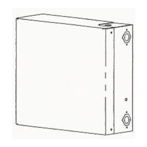
Mounted Unit
1 |
P a g e
Advertisement
Table of Contents

Related Manuals for Chronomite ER-60/277 16600 Series


Summary of Contents for Chronomite ER-60/277 16600 Series
- Page 1 CHRONOMITE HIGH CAPACITY INSTANT-TEMP WATER HEATERS INSTALLATION AND OPERATION INSTRUCTIONS (277V Models) (Before installation, compare electrical requirements needed for the model of heater selected) TABLE 1 – Electrical Specifications 2 Module Heaters (60-80 amp) Model Wattage Total 1Φ Voltage Circuits...
- Page 2 TABLE 2 – Flow Switch Activation Flow Switch Activation 2 Module Heaters 3 Module Heaters Low Activation (L) 0.35 GPM 0.35 GPM Standard Activation (S) 0.80 GPM 1.20 GPM High Activation (H) 1.80 GPM 2.80 GPM THE MANUFACTURER OF THIS WATER HEATER WILL NOT BE LIABLE FOR ANY DAMAGES CAUSED BY THE FAILURE TO FOLLOW THESE INSTALLATION AND OPERATION INSTRUCTIONS.
- Page 3 Top and Bottom FIGURE 1 - Heater Installation Items Needed for Installation: Item Part No. Title Description Chronomite Instant-Temp HCH See Figure 1 Electrical Conduit Length as required Enter via Top or Bottom 3a/b Inlet / Outlet Valve – ¾” NPT...
- Page 4 ELECTRICAL INSTALLATION: 1. Connect power supply wires appropriately sized and protected by single pole circuit breakers to the input terminals on the heater (hard wired) as shown in the Figure 2 wiring diagrams below. Refer to Table 1 above on Page 1 for the voltage, amp and phase ratings of the supply power. Use 2 X 2 wire plus ground supply wires for the 2 module heaters, and 3 X 2 wire plus ground for the 3 module heaters.
- Page 5 IMPORTANT NOTES: Air in the heater may cause the elements to burn out. If the water lines are serviced or drained upstream of heater, be sure to use the following start up procedure: 1. Turn off electrical supply at circuit breakers. 2.
- Page 6 Temperature Adjustment Potentiometer - (L) and (S) Activation Models The potentiometer allows the factory preset temperature of the heater to be changed in the field. The potentiometer will adjust water temperature between 70°F and 125°F provided the wattage of the heater selected is capable of producing the temperature increase at the requested flow rate.
- Page 7 Chronomite Laboratories, Inc.’s Installation Instructions provided. Chronomite Laboratories, Inc. will repair or exchange parts at the factory at no cost. This warranty is limited to repairing or replacing said products which prove to be defective upon factory inspection FOB City of Industry, CA...
- Page 8 2. Manufacturer is not liable for any water damage or other damages arising directly or indirectly from/and defect in the Chronomite tankless water heater component part(s) or from its use. 3. Manufacturer is not liable under this warranty if the water heater has not been continuously supplied with potable water or the water inlet temperature is above manufacturer recommended maximum temperature.
Need help?
Do you have a question about the ER-60/277 16600 Series and is the answer not in the manual?
Questions and answers