Advertisement
Quick Links
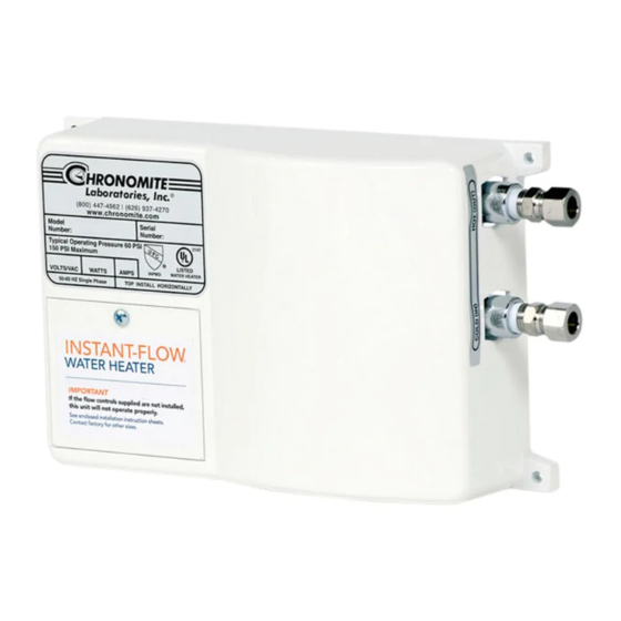
CHRONOMITE INSTANT-FLOW
INSTALLATION AND OPERATION INSTRUCTIONS - (LOW FLOW MODELS)
Instant-Flow
• Dimensions:
• Weight:
• Materials:
• Color:
• Pipe Fittings:
• Pressure Requirements:
• Maximum Operating Temp:
• Flow Switch Activation:
• Flow Switch De-Activation:
• Listings:
THE MANUFACTURER OF THIS WATER HEATER WILL NOT BE LIABLE FOR ANY DAMAGES
DUE TO THE FAILURE TO FOLLOW THESE INSTALLATION AND OPERATION INSTRUCTIONS.
CAUTION:
BEFORE BEGINNING THE INSTALLATION:
A)
B)
1. Remove electrical access cover. Attach conduit to the conduit access hole. Then feed wires. Do not attach wiring.
2. Mount unit horizontally against the wall so the silver label reads correctly (See Fig. 1). Mount with four screws
through the flanges located on each corner using molly anchors or fasteners.
CAUTION: Heating elements may burn out if unit is not mounted horizontally.
3. Connect plumbing. Use
compression fittings supplied for ease of installation. Do not apply heat to these fittings.
4. Run water through the unit to expel all air bubbles. Check for leaks at all fitting joints.
5. Connect wiring. Attach ground wire to center terminal and hot wires to outer terminals (See Fig. 3)
6. Replace electrical access cover. Turn on the circuit breaker. The unit is now ready for use.
7. Local plumbing and electrical codes must be followed in the installation of this water heater and it's accessories.
8. Failure to comply with code requirements voids the warranty.
9. Failure to install faucet flow control as shown on Fig. 2 will cause unsatisfactory operation of the heater.
(Before installation, compare electrical needed for the model of heater selected)
Model No.
SR-15L
SR-15L
SR-20L
SR-20L
SR-20L
SR-20L
SR-30L
6¼" x 9
x 2 ¾
5/8"
5 lbs.
Rugged cast aluminum alloy casing, Celcon waterways, nichrome parts
White (unless stainless steel housing)
Female
NPT standard pipe thread
¼"
25 PSI Minimum, 150 PSI Maximum (300 PSI tested) No pressure relief valve needed
unless required by local codes.
140°F
.4 GPM
.35 GPM
UL, HUD, IAPMO
Turn off the circuit breaker to avoid dangerous electrical shocks.
Turn off the water supply.
tapered national pipe thread at cold water inlet and hot water outlet (See Fig. 1). Use
¼"
TABLE 1
Wattage
Voltage
Breaker
1800
110/120
4150
277
2400
110/120
4160
208
4800
220/240
5540
277
3600
110/120
"
WATER HEATER
Size
15A
15A
20A
20A
20A
20A
30A
Specifications:
Advertisement

Related Manuals for Chronomite SR-15L


Summary of Contents for Chronomite SR-15L
- Page 1 CHRONOMITE INSTANT-FLOW WATER HEATER INSTALLATION AND OPERATION INSTRUCTIONS - (LOW FLOW MODELS) (Before installation, compare electrical needed for the model of heater selected) TABLE 1 Model No. Wattage Voltage Breaker Size SR-15L 1800 110/120 SR-15L 4150 SR-20L 2400 110/120 SR-20L...
-
Page 2: Important Notes
Faucet flow controls must be attached to the faucet to allow the water heating system to operate more effectively (See Fig. 2, pg. 3 for installation). Item Part No. Names Description SR-_ _L Chronomite Instant-Flow SR Heater Models shown in Table 1 Electrical junction box Electrical conduit ½” conduit, length as required Electrical wire... - Page 3 SR-15L, SR-20L, SR-30L Note: MP=Male Pipe FP= female Pipe Comp=Compression Fittings (page 2) OPERATION INSTRUCTIONS Turn the hot water fixture to activate the flow switch. The flow switch activates at .4 gallons per minute (GPM) and deactivates at .35 gallons per minute (GPM).
-
Page 4: Troubleshooting Guide
(1) year from the date of purchase. The above warranty applies to original purchaser if unit is installed per Chronomite Laboratories, Inc.’s Installation Instructions. Chronomite Laboratories, Inc. will repair or exchange parts at the factory at no cost. This warranty is limited... - Page 5 F.O.B. City of Industry, California. Chronomite Laboratories Inc. 17451 Hurley Street City of Industry, CA 91744 Toll Free Technical Hotline (800) 447-4962 Telephone (626) 937-4270 #929 rev. 9 5/06/2010...
Need help?
Do you have a question about the SR-15L and is the answer not in the manual?
Questions and answers