Table of Contents
Advertisement
Available languages
Available languages
Quick Links
INSTALLATION INSTRUCTIONS
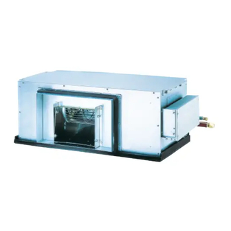
Air Conditioner
This air conditioner uses the refrigerant R410A.
Model No.
Indoor Unit
Type
Indoor Unit Type
H1
Fresh Air Intake Duct
ENGLISH
Read through the Installation Instructions before you proceed with the installation.
In particular, you will need to read under the "IMPORTANT!" section at the top of the page.
B.INDONESIA
Bacalah seluruh Petunjuk Pemasangan sebelum Anda melakukan pemasangan.
Secara khusus, Anda perlu membaca bagian " PENTING! " di bagian atas halaman.
CV6233311357
85464369764022
Rated Capacity
140
S-140MH1H5
S-224MH1H5
224
280
S-280MH1H5
ACXF60-21161
Advertisement
Table of Contents

Related Manuals for Panasonic S-140MH1H5


Summary of Contents for Panasonic S-140MH1H5
- Page 1 Indoor Unit Rated Capacity Type Indoor Unit Type Fresh Air Intake Duct S-140MH1H5 S-224MH1H5 S-280MH1H5 ENGLISH Read through the Installation Instructions before you proceed with the installation. In particular, you will need to read under the “IMPORTANT!” section at the top of the page.
-
Page 2: Important
IMPORTANT! • Provide a power outlet to be used exclusively for each unit. Please Read Before Starting • Provide a power outlet exclusively for This air conditioner must be installed by the sales dealer each unit, and full disconnection means or installer. - Page 3 CAUTION • Keep the fire alarm and …In a Snowy Area (for Heat Pump- WARNING the air outlet at least 1.5 m type Systems) away from the unit. Install the outdoor unit on a raised • In the area where the platform that is higher than drifting snow.
- Page 4 When Servicing Others CAUTION • Do not sit or step on • Turn the power OFF at the main WARNING the unit, you may fall power box (mains) before opening the down accidentally. unit to check or repair electrical parts and wiring.
-
Page 5: Table Of Contents
CONTENTS Page Page IMPORTANT! ........2 6. -
Page 6: General
1. GENERAL 1-3. Type of Copper Tube and Insulation Material If you wish to purchase these materials separately from a local This booklet briefly outlines where and how to install the source, you will need: air conditioning system. Please read over the entire set of Deoxidized annealed copper tube for refrigerant tubing. -
Page 7: Selecting The Installation Site
2. SELECTING THE INSTALLATION SITE 2-1. Indoor Unit AVOID: ● areas where leakage of flammable gas may be expected. ● places where large amounts of oil mist exist. ● direct sunlight. ● locations near heat sources which may affect the performance of the unit. ●... -
Page 8: How To Install The Indoor Unit
3. HOW TO INSTALL THE INDOOR UNIT ■ Fresh Air Intake Duct Type (H1 Type) 3-1. Required Minimum Space for Installation and Service (1) Dimensions of suspension bolt pitch and unit Type 140 Types 224 / 280 Unit: mm Unit: mm Top view Top view Minimum 1100... - Page 9 (2) Dimensions of indoor unit Type 140 Unit : mm 1 Refrigerant liquid tubing (Flare) ø9.52 mm 2 Refrigerant gas tubing (Flare) ø15.88 mm 3 Power supply inlet 7x100=700 4 Drain port 25A 22 - ø3.2 hole 5 Air intake duct connecting side flange (Whole circumference) ø20 hole (For suspension bolt) 6 Air discharge duct connecting side flange...
-
Page 10: Suspending The Indoor Unit
3-2. Suspending the Indoor Unit Depending on the ceiling type: 1. Check the suspension bolt pitch. 2. Ensure that the ceiling is strong enough to support the weight of the unit. 3. To prevent the unit from dropping, firmly fasten the suspension bolts as shown in the figure below. Unit: mm Hole-in-anchor Hexagonal nut (field supply) - Page 11 ■ RAP Valve Kit (Refrigerant Accumulation Protector Valve Kit) (CZ-P160RVK2) When installing a H1 type indoor unit, you must also install the RAP Valve Kit (CZ-P160RVK2). ● Necessary number of connecting RAP valve kit per one indoor unit. Indoor unit type 224/280 2 kits Necessary number...
-
Page 12: Installing The Refrigerant Tubing
3-3. Installing the Refrigerant Tubing The size of the refrigerant tubing is as shown in the table below. Table 3-1 Type ø15.88 ø25.4 ø25.4 Gas tube (Flare connection) (Brazing connection) (Brazing connection) ø9.52 (Flare connection) ø12.7 (Flare connection) ø12.7 (Flare connection) Tightening torque (approximate) Tightening torque (approximate) Tightening torque (approximate) -
Page 13: Installing The Drain Piping
3-4. Installing the Drain Piping Sealing tape (1) Prepare standard hard PVC pipe (O.D. 32 mm) for the drain and use the supplied drain socket to prevent water leaks. The PVC pipe must be purchased separately. When doing this, apply adhesive for the PVC pipe at the connection point. Drain socket (2) If connecting a drain socket (supplied) to the threaded drain port, first wrap the (supplied) -
Page 14: Caution For Ducting Work
3-5. Caution for Ducting Work • This unit has high static pressure. In case of small pressure resistance (for instance, a short duct), install an airflow control damper (field supply) for adjusting airflow volume as airflow volume / airflow noise increases. •... -
Page 15: Indoor Fan Performance
3-6. Indoor Fan Performance The vertical axis is the External Static Pressure (Pa) while the horizontal axis represents the Airflow (m /hour). If the external static pressure is too great (due to long extension of duct, for example), the airflow volume may drop too low at each air outlet. -
Page 16: Electrical Wiring
4. ELECTRICAL WIRING 4-1. General Precautions on Wiring (1) Before wiring, confirm the rated voltage of the unit as shown on its nameplate, then carry out the wiring closely following the wiring diagram. (2) Provide a power outlet to be used exclusively for each unit and a circuit breaker for overcurrent protection should be provided in the exclusive line. -
Page 17: Wiring System Diagrams
4-3. Wiring System Diagrams Indoor unit (No. 1) ex.) ME2 Type Power supply Outdoor unit 220-230-240V~ 50-60Hz INV unit Ground Power supply 380-400-415V 3N~ 50Hz Remote controller 380-400V 3N~ 60Hz Ground Indoor unit (No. 2) Inter-outdoor unit control wiring Power supply 220-230-240V~ 50-60Hz Outdoor unit Ground... - Page 18 CAUTION (1) When linking the outdoor units in a network, disconnect the terminal extended from the short plug from all outdoor units except any one of the outdoor units. (When shipping: In shorted condition.) For a system without link (no wiring connection between outdoor units), do not remove the short plug. (2) Do not install the inter-unit control wiring in a way that forms a loop.
- Page 19 (5) Use shielded wires for inter-unit control wiring (c) and ground the shield on both sides, otherwise misoperation from noise Shielded wire may occur. (Fig. 4-6) Connect wiring as shown in Section “4-3. Wiring System Diagrams”. (Functional earthing) (Functional earthing) (6) •...
-
Page 20: How To Process Tubing
5. HOW TO PROCESS TUBING 5-1. Connecting the Refrigerant Tubing Use of the Flaring Method Many of conventional split system air conditioners employ the flaring method to connect refrigerant tubes that run between indoor and outdoor units. In this method, the copper tubes are flared at each end and connected with flare nuts. Flaring Procedure with a Flare Tool (1) Cut the copper tube to the required length with a tube cutter. -
Page 21: Connecting Tubing Between Indoor And Outdoor Units
5-2. Connecting Tubing Between Indoor and Outdoor Units (1) Tightly connect the indoor-side refrigerant tubing extended from the wall with the outdoor-side tubing. Indoor Unit Tubing Connection Type ø15.88 ø25.4 ø25.4 Gas tube (Flare connection) (Brazing connection) (Brazing connection) ø9.52 (Flare connection) ø12.7 (Flare connection) ø12.7 (Flare connection) Tightening torque (approximate) -
Page 22: Insulating The Refrigerant Tubing
5-3. Insulating the Refrigerant Tubing Tubing Insulation • Thermal insulation must be applied to all units tubing, including distribution joint (field supply). * For gas tubing, the insulation material must be heat resistant to 120°C or above. Two tubes arranged together For other tubing, it must be heat resistant to 80°C or above. -
Page 23: How To Install Timer Remote Controller (Optional Part)
6. HOW TO INSTALL TIMER REMOTE CONTROLLER (OPTIONAL PART) NOTE Refer to the Installation Instructions attached to the optional Timer Remote Controller. 7. HOW TO INSTALL WIRELESS REMOTE CONTROLLER NOTE Refer to the Installation Instructions attached to the optional Wireless Remote Controller. 8. - Page 24 <How to clean the filter> 1. Remove the air filter from the air intake grille. 2. Use a vacuum cleaner to remove light dust. If there is sticky dust on the filter, wash the filter in lukewarm, soapy water, rinse it in clean water, and dry it. Certain metal edges and the condenser fins are sharp and may cause injury if handled improperly;...
- Page 25 Check Before Requiring Services ● Symptom Cause Remedy Power failure or after power failure Press ON/OFF operation button on remote controller again. Air conditioner does not • Switch on power if breaker is turned off. run at all although power Operation button is turned off.
- Page 26 IMPORTANT INFORMATION REGARDING THE REFRIGERANT USED N OT E Refer to the Installation Instructions attached to the outdoor unit.
- Page 27 PENTING! • Sediakan stopkontak untuk digunakan secara khusus oleh masing-masing unit. Harap Baca Sebelum Memulai • Sediakan stopkontak untuk digunakan secara khusus untuk masing-masing unit, dan pemutusan sepenuhnya Penyejuk udara ini harus dipasang oleh dealer penjualan berarti semua kontak kutubnya terpisah dan harus atau pemasang.
- Page 28 Saat Menyervis • Hindari area yang banyak mengandung gas asam sulfat, gas korosif, atau rentan mengalami erosi akibat garam. • MATIKAN daya di kotak daya utama Kondisi ini dapat menimbulkan korosi (daya listrik) sebelum membuka unit untuk pada pipa tembaga dan bagian yang memeriksa atau memperbaiki suku cadang dan dipatri.
- Page 29 DAFTAR ISI Halaman Halaman PENTING! ........27 6.
- Page 30 1. UMUM 1-3. Tipe Pipa Tembaga dan Bahan Insulasi Jika Anda ingin membeli bahan ini secara terpisah dari sumber Buklet ini menguraikan secara singkat tempat dan cara lokal, Anda akan memerlukan: memasang sistem penyejuk udara. Baca semua petunjuk Pipa tembaga tempa deoksidasi untuk pipa refrigeran. untuk unit dalam ruang dan luar ruang serta pastikan semua komponen aksesori yang tercantum disertakan dengan sistem Insulasi polietilena berbusa untuk pipa tembaga...
- Page 31 2. MEMILIH TEMPAT PEMASANGAN 2-1. Unit Dalam Ruang HINDARI: ● area yang memungkinkan terjadinya kebocoran gas yang mudah terbakar. ● tempat yang mengandung banyak uap oli. ● cahaya matahari langsung. ● lokasi di dekat sumber panas yang dapat mempengaruhu performa unit. ●...
- Page 32 3. CARA MEMASANG UNIT DALAM RUANG ■ Tipe Saluran Masuk Udara Segar (Tipe H1) 3-1. Ruang Minimum yang Diperlukan untuk Pemasangan dan Servis (1) Dimensi jarak-bagi dan unit baut penggantung Tipe 140 Tipe 224 / 280 Satuan: mm Satuan: mm Tampak atas Tampak atas Minimum 1100...
- Page 33 (2) Dimensi unit dalam ruang Tipe 140 Satuan: mm 1 Pipa cairan refrigeran (Flare) ø9,52 mm 2 Saluran gas refrigeran (Flare) ø15,88 mm 3 Saluran masuk catu daya 7x100=700 4 Port pembuangan 25A 22 - Lubang ø3,2 5 Flens sisi sambungan saluran masuk udara Lubang ø20 (Lubang untuk baut (Keliling penuh) penggantung)
- Page 34 3-2. Menggantung Unit Dalam Ruang Tergantung pada tipe plafon: 1. Periksa jarak-bagi baut penggantung. 2. Pastikan bahwa plafon cukup kuat untuk menahan bobot unit. 3. Untuk mencegah jatuhnya unit, kencangkan baut penggantung dengan baik seperti ditampilkan pada gambar di bawah ini. Satuan: mm Angkur dalam lubang Mur segi enam (tidak disertakan)
- Page 35 ■ Kit Katup RAP (Kit Katup Pelindung Akumulasi Refrigeran) (CZ-P160RVK2) Ketika memasang unit dalam ruangan tipe H1, Anda juga harus memasang Kit Katup tipe H1 (CZ-P160RVK2). ● Jumlah sambungan kit katup RAP yang dibutuhkan per unit dalam ruang. Tipe unit dalam ruang 224/280 2 kit Jumlah yang dibutuhkan...
- Page 36 3-3. Memasang Pipa Refrigeran Ukuran pipa refrigeran ditunjukkan pada tabel berikut. Tabel 3-1 Tipe ø15,88 ø25,4 ø25,4 Pipa gas (Sambungan flare) (Sambungan pematrian) (Sambungan pematrian) ø9,52 (Sambungan flare) ø12,7 (Sambungan flare) ø12,7 (Sambungan flare) Torsi pengencangan (sekitar) Torsi pengencangan (sekitar) Torsi pengencangan (sekitar) Pipa cairan : 34 ~ 42 N •...
- Page 37 3-4. Memasang Pipa Pembuangan Penyegel (1) Siapkan pipa PVC keras standar (O.D. 32 mm) untuk pembuangan dan gunakan soket pembuangan yang disertakan untuk mencegah kebocoran air. Pipa PVC harus dibeli secara terpisah. Ketika menyambung, oleskan adesif/lem untuk pipa PVC pada titik sambungan.
- Page 38 3-5. Perhatian tentang Pengaturan Saluran • Unit ini memiliki tekanan statis yang tinggi. Jika ada hambatan tekanan yang kecil (contohnya, saluran yang pendek), pasang peredam kontrol aliran udara (tidak disertakan) untuk mengatur volume aliran udara ketika volume aliran udara itu/derau aliran udara bertambah. •...
- Page 39 3-6. Kinerja Kipas Dalam Ruang Sumbu vertikal adalah Tekanan Statik Eksternal (Pa) sedangkan sumbu horizontal menggambarkan Aliran Udara (m /jam). Jika tekanan statik eksternal terlalu besar (karena panjangnya saluran, misalnya), volume aliran udara mungkin menjadi terlalu rendah pada masing-masing saluran keluar udara. Tipe 50Hz 240V...
- Page 40 4. KABEL LISTRIK 4-1. Tindakan Pencegahan Umum tentang Pengkabelan (1) Sebelum melakukan pengkabelan, periksa tegangan rating unit sebagaimana tertera pada pelat nama, kemudian lakukan pengkabelan sesuai dengan diagram pengkabelan. (2) Sediakan stopkontak untuk digunakan secara khusus untuk masing-masing unit dan pemutus arus untuk perlindungan arus berlebih harus diberikan pada jalur khusus.
- Page 41 4-3. Diagram Sistem Pengkabelan Unit dalam ruang (No. 1) msl.) Tipe ME2 Catu daya Unit luar ruang 220-230-240V~ 50-60Hz Unit INV Pentanahan Catu daya Pengendali 380-400-415V 3N~ 50Hz jarak jauh 380-400V 3N~ 60Hz Pentanahan Unit dalam ruang (No. 2) Kabel kontrol antar unit luar ruang Catu daya 220-230-240V~ 50-60Hz Unit luar ruang...
- Page 42 PERHATIAN (1) Saat menghubungkan unit luar ruang ke dalam suatu jaringan, lepaskan terminal yang berasal dari shot plug dari semua unit luar ruang kecuali satu unit luar ruang. (Ketika mengirim: Dalam kondisi shorted/bypass.) Untuk sistem tanpa sambungan (tidak ada sambungan kabel antara unit luar ruang), jangan melepas short plug. (2) Jangan memasang kabel kontrol antar-unit sedemikian rupa sehingga membentuk loop.
- Page 43 (5) Gunakan kabel berpelindung untuk kabel kontrol antar-unit (c) dan tanahkan Kabel berpelindung pelindung di kedua sisinya, jika tidak kesalahan pengoperasian akibat derau bisa terjadi. (Gbr. 4-6) Sambung kabel seperti yang ditunjukkan di Bagian “4-3. Diagram Sistem Pengkabelan”. (Pentanahan (Pentanahan fungsional) fungsional) (6) •...
- Page 44 5. CARA MEMPROSES PEMIPAAN 5-1. Menyambungkan Pipa Refrigeran Penggunaan Metode Pemekaran Banyak penyejuk udara dengan sistem terpisah (split) konvensional menggunakan metode flare untuk menyambungkan pipa-pipa refrigeran antara unit dalam dan luar ruang. Pada metode ini, masing-masing ujung pipa tembaga diperbesar diameternya (dimekarkan) dan disambungkan dengan mur flare.
- Page 45 5-2. Menyambungkan Pipa Antara Unit Dalam dan Luar Ruang (1) Sambungkan dengan kencang pipa refrigeran pada sisi dalam ruang yang muncul dari dinding dengan pipa sisi luar ruang. Sambungan Pipa Unit Dalam Ruang Tipe ø15,88 ø25,4 ø25,4 Pipa gas (Sambungan flare) (Sambungan pematrian) (Sambungan pematrian) ø9,52 (Sambungan flare)
- Page 46 5-3. Memasang Insulasi pada Pipa Refrigeran Insulasi Pipa • Insulasi termal harus diberikan kepada semua pipa unit, termasuk sambungan distribusi (tidak disertakan). * Untuk pipa gas, bahan insulasi harus tahan panas sampai suhu 120°C atau lebih. Dua pipa disusun bersama Untuk pipa lain, harus tahan panas sampai suhu 80°C atau lebih.
- Page 47 6. CARA MEMASANG PENGENDALI JARAK JAUH PEWAKTU (KOMPONEN OPSIONAL) CATATAN Baca Petunjuk Pemasangan yang terlampir ke Pengendali Jarak Jauh Pewaktu. 7. CARA MEMASANG PENGENDALI JARAK JAUH NIRKABEL CATATAN Baca Petunjuk Pemasangan yang terlampir pada Pengendali Jarak Jauh Nirkabel opsional. 8. LAMPIRAN ■...
- Page 48 <Cara membersihkan filter> 1. Lepaskan filter udara dari kisi udara masuk. 2. Gunakan penyedot debu untuk mengangkat debu ringan. Jika ada debu yang menempel pada filter, bersihkan filter dengan air bersabun suam-suam kuku, bilas dengan air bersih, dan keringkan. Pinggiran logam dan sirip kondensor tertentu tajam dan bisa menyebabkan cedera jika tidak ditangani ●...
- Page 49 Pemeriksaan Sebelum Memerlukan Servis ● Gejala Penyebab Pemecahan Kegagalan daya atau setelah kegagalan Tekan tombol pengoperasian ON/OFF lagi di unit pengendali daya jarak jauh. Penyejuk udara tidak • Nyalakan daya jika pemutus dinonaktifkan. beroperasi sama sekali Tombol operasi dimatikan. • Jika pemutus mengalami trip (padam), hubungi dealer Anda meski daya dinyalakan.
- Page 50 INFORMASI PENTING MENGENAI REFRIGERAN YANG DIGUNAKAN CATATAN Baca Petunjuk Pemasangan yang terlampir pada unit luar ruang.
- Page 51 – CATATAN –...
- Page 52 Printed in China ACXF60-21161 85464369764022 DC1213-30721...
Need help?
Do you have a question about the S-140MH1H5 and is the answer not in the manual?
Questions and answers