Panasonic U-4LE1E5 Installation Instructions Manual
Mini vrf system air conditioner
Hide thumbs
Also See for U-4LE1E5:
- Installation instructions manual (224 pages) ,
- Service manual (141 pages) ,
- Operating instructions manual (180 pages)
Table of Contents
Advertisement
Quick Links
INSTALLATION INSTRUCTIONS
INSTRUCTIONS D'INSTALLATION
EINBAUANLEITUNG
ISTRUZIONI PER L'INSTALLAZIONE
INSTRUÇÕES DE INSTALAÇÃO
ΟΔΗΓΙΕΣ ΤΟΠΟΘΕΤΗΣΗΣ
INSTRUCCIONES DE INSTALACIÓN
INSTALLATIE-INSTRUCTIES
ИНСТРУКЦИИ ЗА МОНТАЖ
ИНСТРУКЦИИ ПО УСТАНОВКЕ
ВКАЗІВКИ ЩОДО ВСТАНОВЛЕННЯ
Outdoor Units
U-4LE1E5, U-5LE1E5, U-6LE1E5, U-4LE1E8, U-5LE1E8, U-6LE1E8
Unités extérieures
U-4LE1E5, U-5LE1E5, U-6LE1E5, U-4LE1E8, U-5LE1E8, U-6LE1E8
Außeneinheiten
U-4LE1E5, U-5LE1E5, U-6LE1E5, U-4LE1E8, U-5LE1E8, U-6LE1E8
Unità esterne
U-4LE1E5, U-5LE1E5, U-6LE1E5, U-4LE1E8, U-5LE1E8, U-6LE1E8
Unidades exteriores
U-4LE1E5, U-5LE1E5, U-6LE1E5, U-4LE1E8, U-5LE1E8, U-6LE1E8
Εξωτερικές Μονάδες
U-4LE1E5, U-5LE1E5, U-6LE1E5, U-4LE1E8, U-5LE1E8, U-6LE1E8
Unidades exteriores
U-4LE1E5, U-5LE1E5, U-6LE1E5, U-4LE1E8, U-5LE1E8, U-6LE1E8
Buiteneenheden
U-4LE1E5, U-5LE1E5, U-6LE1E5, U-4LE1E8, U-5LE1E8, U-6LE1E8
Външни модули
U-4LE1E5, U-5LE1E5, U-6LE1E5, U-4LE1E8, U-5LE1E8, U-6LE1E8
Внешние блоки
U-4LE1E5, U-5LE1E5, U-6LE1E5, U-4LE1E8, U-5LE1E8, U-6LE1E8
Ззовнішні агрегати
U-4LE1E5, U-5LE1E5, U-6LE1E5, U-4LE1E8, U-5LE1E8, U-6LE1E8
85464369493021 2011
AMP Air Conditioning
– Mini VRF System Air Conditioner –
for Refrigerant R410A
– Climatiseur Système Mini-VRF –
pour réfrigérant R410A
– Mini VRF System-Klimaanlage –
für Kühlmittel R410A
– Condizionatore d'aria VRF Mini –
per refrigerante R410A
– Sistema de Ar Condicionado Mini VRF –
para Refrigerante R410A
– Κλιματιστικό σύστημα Mini VRF –
για το ψυκτικό R410A
– Acondicionador de aire del sistema Mini VRF –
para refrigerante R410A
– Mini VRF Systeem Airconditioner –
voor koelmiddel R410A
– Климатик мини система VRF –
за хладилен агент R410A
– Кондиционер системы Mini VRF –
для хладагента R410A
– Система кондиціювання повітря Mini VRF –
для охолоджувача R410A
www.ampair.co.uk | sales@ampair.co.uk
EN
FR
DE
IT
PT
GR
ES
NL
BL
RU
UK
Advertisement
Table of Contents

Related Manuals for Panasonic U-4LE1E5


Summary of Contents for Panasonic U-4LE1E5
- Page 1 для хладагента R410A – Система кондиціювання повітря Mini VRF – ВКАЗІВКИ ЩОДО ВСТАНОВЛЕННЯ для охолоджувача R410A Outdoor Units U-4LE1E5, U-5LE1E5, U-6LE1E5, U-4LE1E8, U-5LE1E8, U-6LE1E8 Unités extérieures U-4LE1E5, U-5LE1E5, U-6LE1E5, U-4LE1E8, U-5LE1E8, U-6LE1E8 Außeneinheiten U-4LE1E5, U-5LE1E5, U-6LE1E5, U-4LE1E8, U-5LE1E8, U-6LE1E8 Unità esterne...
-
Page 2: Indoor Unit
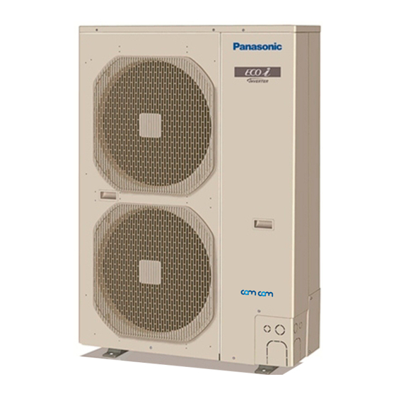
– Mini VRF System Air Conditioner – for Refrigerant R410A ■ R410A Models Model No. Outdoor Units 4 hp 5 hp 6 hp U-4LE1E5 U-5LE1E5 U-6LE1E5 U-4LE1E8 U-5LE1E8 U-6LE1E8 * Refrigerant R410A is used in the outdoor units. hp = horsepower... -
Page 3: Important
Circuit breaker must be incorporated in the fixed wiring equipment is connected only to a supply with a short- in accordance with the wiring regulations. circuit power Ssc greater than or equal to the value in the table. U-4LE1E5 U-5LE1E5 U-6LE1E5 Circuit breaker 30 A... - Page 4 When Installing… Handle liquid refrigerant carefully as it may cause frostbite. Select an installation location which is rigid and strong When Servicing enough to support or hold the unit, and select a location for easy maintenance. • Turn the power OFF at the main power box …In a Room (mains) before opening the unit to check or repair Properly insulate any tubing run inside a room to prevent...
-
Page 5: Check Of Density Limit
Check of Density Limit The standards for minimum room volume are as follows. (1) No partition (shaded portion) The room in which the air conditioner is to be installed requires a design that in the event of refrigerant gas leaking out, its density will not exceed a set limit. The refrigerant (R410A), which is used in the air conditioner, is safe, without the toxicity or combustibility of ammonia, and is not restricted by laws imposed to protect the ozone layer. -
Page 6: Precautions For Installation Using New Refrigerant
Precautions for Installation Using New R407C tools Refrigerant Item compatible Remarks tool? with 1. Care regarding tubing R410A? 1-1. Process tubing Manifold Types of refrigerant, ● Material: Use C1220 phosphorous deoxidized copper gauge refrigerating machine oil, specified in JIS H3300 “Copper and Copper Alloy Seamless and pressure gauge are Pipes and Tubes”. -
Page 7: Table Of Contents
CONTENTS Page Page IMPORTANT! ........2 5. -
Page 8: General
Table 1-1 (Outdoor Unit) ø12.7 ø15.88 ø19.05 (mm) Tubing size Q’ty Liquid ø9.52 ø9.52 Part tubing (mm) U-4LE1E5 U-5LE1E5 U-6LE1E5 Figure name U-4LE1E8 U-5LE1E8 U-6LE1E8 Unit: mm, hp = horsepower (4 hp) (5 hp) (6 hp) Note : In case the total capacity of connected indoor units exceeds the total capacity of the outdoor units, select the main tubing size for the total capacity of the outdoor units. -
Page 9: 1-7. Additional Refrigerant Charge
1-7. Additional Refrigerant Charge Table 1-10 Ranges that Apply to Refrigerant Tubing Lengths and to Differences in Installation Heights Additional refrigerant charge amount is calculated from the Items Marks Contents Length (m) liquid tubing total length as follows. Actual ≤ 120 Table 1-7 Amount of Refrigerant Charge Per Meter, length Max. -
Page 10: 1-11. Installing Distribution Joint
Minimum indoor volume & floor area relative to the amount of refrigerant are roughly as given in the following table. Types of vertical trap specifications 337.5 (When using ball valve (field supply)) 324.0 310.5 Main tubing 297.0 283.5 270.0 256.0 243.0 Indoor unit (more than 2 units) Ball valve... -
Page 11: 1-13. Example Of Tubing Size Selection And Refrigerant
1-13. Example of Tubing Size Selection and Example: Refrigerant Charge Amount Additional refrigerant charging Based on the values in Tables 1-2, 1-3, 1-4 and 1-7, use the liquid tubing size and length, and calculate the amount of additional refrigerant charge using the formula below. Main tube of unit Required additional... -
Page 12: Selecting The Installation Site
Checking of limit density Exhaust fan Density limit is determined on the basis of the size of a room Hot air using an indoor unit of minimum capacity. For instance, when an indoor unit is used in a room (floor area 7.43 m ×... -
Page 13: 2-2. Air-Discharge Chamber For Top Discharge
In case of multiple installations 2-3. Installing the Unit in Heavy Snow Areas ● Provide a solid base (concrete block, 10 × 40 cm beams or In locations with strong wind, snow-proof ducting should be equal), a minimum of 15 cm above ground level to reduce fitted and direct exposure to the wind should be avoided as humidity and protect the unit against possible water damage much as possible. -
Page 14: 2-5. Dimensions Of Air-Discharge Chamber
2-5. Dimensions of Air-Discharge Chamber Reference diagram for air-discharge chamber (field supply) Unit: mm Air Intake Air Intake Installation anchoring holes (4-R6.5) / Anchor bolt M10 (110) (316) (303) discharge Air Intake discharge Required space around outdoor unit If the air discharge chamber is used, the space shown below must be secured around the outdoor unit. If the unit is used without the required space, a protective device may activate, preventing the unit from operating. -
Page 15: 2-6. Dimensions Of Snow-Proof Vents
2-6. Dimensions of Snow-Proof Vents Reference diagram for snow-proof vents (field supply) Unit: mm Air Intake (295) Air discharge Mounting hole (2-13 × 18 hole) (303) Air discharge Air discharge Air Intake Required space around outdoor unit [Obstacle to the rear of unit] ●... - Page 16 [Obstacle to the front of unit] ● Top is blocked by an obstacle: ● Top is open: Unit: mm (1) Single-unit installation 250* 1000 Unit: mm Min. M or more (2) Multiple-unit installation (2 or more units) Min. I Min. I or more or more The amount of space is required for removing the screws...
-
Page 17: How To Install The Outdoor Unit
3-3. Routing the Tubing and Wiring 3. HOW TO INSTALL THE OUTDOOR UNIT ● The tubing and wiring can be extended out in 4 directions 3-1. Installing the Outdoor Unit (front, rear, right, and down): ● The service valves are housed inside the unit. To access ●... -
Page 18: 4-2. Recommended Wire Length And Wire Diameter For
10 – 16 A Circuit P1, R1 Wire size Max. length Fuse breaker E1 (73, 106, 140) Max. 60 m 10 – 16 A U-4LE1E5 4 mm 21 m 25 A 30 A U-5LE1E5 6 mm 24 m 35 A 40 A... -
Page 19: 4-3. Wiring System Diagrams
CAUTION (1) When linking outdoor units in a network, disconnect the terminal extended from the short plug (CN-TERMINAL, 2P Black, location: right bottom on the outdoor main control PCB) from all outdoor units except any one of the outdoor units. (When shipping: In shorted condition) For a system without link (no connection wiring between outdoor units), do not remove the short plug. -
Page 20: Amp Air Conditioning
■ Wiring sample How to connect wiring to the terminal ■ For stranded wiring Outdoor unit : single-phase model (1) Cut the wire end with cutting pliers, then strip the insulation to expose the stranded wire about 10 mm and tightly twist Use this screw when the wire ends. -
Page 21: How To Process Tubing
5. HOW TO PROCESS TUBING Caution Before Connecting Tubes Tightly (1) Apply a sealing cap or water-proof tape to prevent dust or Both the liquid tubing and the gas tubing sides are connected water from entering the tubes before they are used. by a flare nut. -
Page 22: 5-2. Connecting Tubing Between Indoor And Outdoor
5-2. Connecting Tubing Between Indoor and Outdoor 5-3. Insulating the Refrigerant Tubing Units Tubing Insulation (1) Tightly connect the indoor-side refrigerant tubing extended ● Standard Selection of Insulation Material from the wall with the outdoor-side tubing. Under the environment of the high temperature and high (2) To fasten the flare nuts, apply specified torque as shown in humidity, the surface of the insulation material is easy to the table below. -
Page 23: Air Purging
If the exterior of the outdoor unit valves 5-5. Finishing the Installation Apply putty here has been finished with a square duct After finishing insulating and taping CAUTION covering, make sure you allow sufficient over the tubing, use sealing putty to space to use the valves and to allow the seal off the hole in the wall to prevent panels to be attached and removed. -
Page 24: Test Run.
Leak test Manifold valve (1) Attach a manifold valve (with pressure gauges) and dry nitrogen gas cylinder to this service port with charge hoses. CAUTION Pressure gauge Use a manifold valve for air purging. If it is not available, use a stop valve for this purpose. The “Hi” knob of the manifold valve must always be kept closed. -
Page 25: 7-1. Preparing For Test Run
7. TEST RUN Manifold valve 7-1. Preparing for Test Run ● Before attempting to start the air conditioner, check the following points. Pressure (1) All loose matter is removed from the cabinet especially gauge steel filings, bits of wire, and clips. Valve (2) The control wiring is correctly connected and all electrical connections are tight. -
Page 26: 7-2. Test Run Procedure
7-2. Test Run Procedure Items to Check Before the Test Run 1. Turn the remote power switch on at least 5 hours before the test, in order to energize the crankcase heater. 2. Turn the outdoor service valves (2 locations) to the full-open positions. ●... -
Page 27: 7-3. Outdoor Unit Pcb Setting
7-3. Outdoor Unit PCB Setting (for single-phase outdoor unit PCB) S004 D303 (LED2) CN-A.ADD D302 (LED1) CN-MODE S003 S002 CN-TERMINAL (for 3-phase outdoor unit PCB) S004 D303 (LED2) CN-A.ADD D302 (LED1) CN-MODE S003 S002 CN-TERMINAL Fig. 7-4 AMP Air Conditioning www.ampair.co.uk | sales@ampair.co.uk... -
Page 28: 7-4. Auto Address Setting
● Examples of the No. of indoor units settings 7-4. Auto Address Setting Indoor unit setting (S004) Basic wiring diagram: Example (1) No. of indoor units (Rotary switch, gray) • If link wiring is not used (The inter-unit control wires are not connected to multiple set to 1 1 unit (factory setting) refrigerant systems.) - Page 29 Basic wiring diagram: Example (2) <Case 2> Automatic Address Setting (no compressor operation) • If link wiring is used ● Indoor and outdoor unit power can be turned ON for each * When multiple outdoor units exist, remove the socket that is used to short-circuit the terminal plug (CN-TERMINAL) from system separately.
-
Page 30: Tubing
<Case 3A> Automatic Address Setting in Heating Mode <Case 3B> Automatic Address Setting in Cooling Mode ● Indoor and outdoor unit power cannot be turned ON for each ● Indoor and outdoor unit power cannot be turned ON for each system separately. - Page 31 Automatic Address Setting from the Remote Controller* Display during automatic address setting Selecting each refrigerant system individually for automatic ● On outdoor unit PCB address setting ---Automatic address setting for each system: Item code “A1” ● Press the remote controller timer time button and button at the same time.
-
Page 32: 7-5. Caution For Pump Down
Request concerning recording the indoor/outdoor Remote Controller Test Run Settings unit combination Nos. Press the remote controller button for 4 seconds or longer. Then press the button. After automatic address setting has been completed, be sure to record them for future reference. ●... -
Page 33: 7-6. Meaning Of Alarm Messages
7-6. Meaning of Alarm Messages Alarm Possible cause of malfunction message Table of Self-Diagnostics Functions and Description of Improper setting. This alarm message shows Alarm Displays when the indoor unit for multiple-use is not connected Alarm messages are indicated by the blinking of LED 1 and 2 to the outdoor unit. - Page 34 ЗА ІНФОРМАЦІЄЮ СТОСОВНО ІНШИХ КОМБІНАЦІЙ ЗВЕРТАЙТЕСЯ ДО ІНСТРУКЦІЇ. Discharge gas temperature of the comp. No. 1 is not Made in China detected. Panasonic Corporation Сделано в Китае Temp. sensor is not seated at Вироблено в Китаї Fabricado en China the sensor holder.
- Page 35 Compliance with regulation 842/EC/2006 Article 7(1) requirements DO NOT VENT R410A INTO THE ATMOSPHERE: R410A IS A FLUORINATED GREENHOUSE GAS, COVERED BY THE KYOTO PROTOCOL, WITH A GLOBAL WARMING POTENTIAL (GWP) = 1975. Conformité aux exigences de l’article 7 (1) de la réglementation 842/EC/2006 NE PAS METTRE LE R410A À...
Need help?
Do you have a question about the U-4LE1E5 and is the answer not in the manual?
Questions and answers