Table of Contents
Advertisement
Quick Links
Advertisement
Chapters
Table of Contents

Related Manuals for mundoclima MV6-XMi Series


Summary of Contents for mundoclima MV6-XMi Series
- Page 1 VRF MV6 MV6-XMi SERIES 252T - 900T...
- Page 2 VRF MV6 CONTENTS Part 1 General Information ................4 Part 2 Outdoor Unit Engineering Data ............18 Part 3 System Design and Installation ............215 ............268...
- Page 3 VRF MV6 (This page is intentionally left blank)
-
Page 4: Table Of Contents
VRF MV6 Part 1 General Information Indoor and Outdoor Unit Capacities ............5 External Appearance................7 Outdoor Unit Combinations ..............9 Nomenclature ..................10 Combination Ratio ................12 Selection Procedure ................13... -
Page 5: Indoor And Outdoor Unit Capacities
VRF MV6 1 Indoor and Outdoor Unit Capacities 1.1 Indoor Units 1.1.1 Standard indoor units Table 1-1.1: Standard indoor unit abbreviation codes Abbreviation Abbreviation Type Type code code Q1DN One-way Cassette High Static Pressure Duct Q2DN Two-way Cassette GWMN Wall-mounted Q4AN Compact Four-way Cassette DDLC... - Page 6 VRF MV6 1.3 Outdoor Units Table 1-1.5: Outdoor unit capacity range Capacity Model Name Combination Type MV6-XMi 252T MV6-XMi 280T 10HP MV6-XMi 335T 12HP MV6-XMi 400T 14HP MV6-XMi 450T 16HP MV6-XMi 500T 18HP MV6-XMi 560T 20HP MV6-XMi 615T 22HP MV6-XMi 670T 24HP MV6-XMi 730T 26HP...
-
Page 7: External Appearance
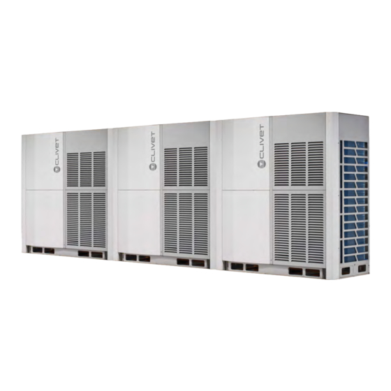
VRF MV6 2 External Appearance 2.1 Indoor Units 2.1.1 Standard indoor units Table 1-2.1: Standard indoor unit appearance One-way Cassette Two-way Cassette Q1DN Q2DN Compact Four-way Cassette Four-way Cassette Q4AN Q4DN Medium Static Pressure Duct High Static Pressure Duct CNT2 Wall-mounted Ceiling &... - Page 8 VRF MV6 2.3 Outdoor Units 2.3.1 Single units Table 1-2.4: Single outdoor unit appearance 8/10/12HP 14/16HP 18/20/22HP 24/26/28/30/32HP (with single fan) (with single fan) (with dual fans) (with dual fans) 2.3.2 Combinations of units Table 1-2.5: Combination outdoor unit appearance 34HP 36/38HP 40HP...
-
Page 9: Outdoor Unit Combinations
VRF MV6 3 Outdoor Unit Combinations Table 1-3.1: Outdoor unit combinations System capacity Modules Number Outdoor branch of units joint kit 25.2 ● 28.0 ● 33.5 ● 40.0 ● 45.0 ● 50.0 ● 56.0 ● — 61.5 ● 67.0 ● 73.0 ●... -
Page 10: Nomenclature
VRF MV6 4 Nomenclature 4.1 Indoor Units 4.1.1 Standard indoor units Q1DN -2 - X D 22 1 ○ ○ ○ ○ ○ ○ ○ Legend Code Remarks Indoor unit type Q1DN: One-way Cassette Q2DN: Two-way Cassette Q4AN: Four-way Cassette Compact Q4DN: Four-way Casse e Q1DN CNT2: Medium Sta c Pressure Duct... - Page 11 VRF MV6 4.2 Heat recovery ventilator - M i D 200 ○ ○ ○ ○ ○ ○ Legend Code Remarks Heat recovery venl ator 2nd generation indoor unit Midea Inverter Series category (D: DC series) Airflow in m3/h 4.3 Outdoor Units MV6 - X 252 T ○...
-
Page 12: Combination Ratio
VRF MV6 5 Combination Ratio Sum of capacity indexes of the indoor units Combination ratio = Capacity index of the outdoor units Table 1-5.1: Indoor and outdoor unit combination ratio limitations Maximum combination ratio Minimum Type Standard indoor Fresh air processing Fresh air processing units and combination ratio units only... -
Page 13: Selection Procedure
VRF MV6 6 Selection Procedure 6.1 Procedure Step 1: Establish design conditions Design temperature and humidity (indoor and outdoor) Required heat load of each room System peak load Piping length, level differences Indoor unit specifications (type and quantity) Step 2: Select indoor units Decide indoor unit safety factor Select indoor unit models ensuring that: Indoor unit capacity corrected for indoor air temperature WB... - Page 14 VRF MV6 6.2 Example The following is a selection example based on total heat load for cooling. Figure 1-6.1: Room plan Room H Room G Room A Room F Room B Room E Room C Room D Step 1: Establish design conditions ...
- Page 15 VRF MV6 Table 1-6.2: Extract from medium static pressure duct (CNT2) cooling capacity table Indoor air temperature Capacity 14°C WB 16°C WB 18°C WB 19°C WB 20°C WB 22°C WB 24°C WB Model index 20°C DB 23°C DB 26°C DB 27°C DB 28°C DB 30°C DB...
- Page 16 VRF MV6 Table 1-6.5: Extract from Table 1-5.2 Combinations of Indoor and outdoor units Outdoor unit capacity Sum of capacity indexes of Maximum number of Capacity connected indoor units (standard connected indoor index indoor units only) units 50.0 250 to 650 56.0 280 to 728 61.5...
- Page 17 VRF MV6 Find the correction factor for piping length and level difference (“K1”) Figure 1-6.3: V6 rate of change in cooling capacity K1 = 0.898 10 20 30 40 50 60 70 80 90 100 110 120 130 140 150 160 170 180 190 200 -100 -110 Notes:...
- Page 18 VRF MV6 Part 2 Outdoor Unit Engineering Data Specifications ..................19 Dimensions ..................30 Installation Space Requirements ............40 Piping Diagrams ................... 41 Wiring Diagrams .................. 47 Electrical Characteristics ..............49 Functional Components and Safety Devices ......... 50 Capacity Tables ..................51 Operating Limits ................
-
Page 19: Specifications
VRF MV6 1 Specifications Table 2‐1.1: 8‐14HP specifications HP 8 10 12 14 Model name (Combination unit) MV6‐XMi 252T MV6‐XMi 280T MV6‐XMi 335T MV6‐XMi 400T Power supply V/Ph/Hz 380‐415/3/50 kW 25.2 28.0 33.5 40.0 Capacity kBtu/h 86.0 95.5 114.3 136.5 5.93 6.75 8.70 9.90 Power input kW Cooling 4.25 4.15 3.85 4.05 EER ... - Page 20 VRF MV6 HP 16‐22 Table 2‐1.2: 16‐22HP specifications HP 16 18 20 22 Model name (Combination unit) MV6‐XMi 450T MV6‐XMi 500T MV6‐XMi 560T MV6‐XMi 615T Power supply V/Ph/Hz 380‐415/3/50 kW 45.0 50.0 56.0 61.5 Capacity kBtu/h 153.5 170.6 191.1 209.8 Power input kW 12.0 12.5 15.1 18.4 Cooling EER 3.75 4.00 3.70 3.35 ...
- Page 21 VRF MV6 HP 24‐32 Table 2‐1.3: 24‐32HP specifications HP 24 26 28 30 32 Model name (Combination unit) MV6‐XMi 670T MV6‐XMi 730T MV6‐XMi 785T MV6‐XMi 850T MV6‐XMi 900T Power supply V/Ph/Hz 380‐415/3/50 kW 67.0 73.0 78.5 85.0 90.0 Capacity kBtu/h 228.6 249.1 267.8 290.0 307.1 20.9 27.4 Power input kW 31.0 24.2 18.1 Cooling ...
- Page 22 VRF MV6 34-40HP Table 2-1.22: 34-40HP Model name (Combination unit) MV6-XMi 950T MV6-XMi 1015T MV6-XMi 1065T MV6-XMi 1120T Combination type 12HP+22HP 14HP+22HP 16HP+22HP 12HP+28HP Power supply V/Ph/Hz 380-415/3/50 95.0 101.5 106.5 112.0 Capacity kBtu/h 324.1 346.3 363.4 382.1 Cooling Power input 27.1 28.2 30.4...
- Page 23 VRF MV6 42-48HP Table 2-1.23: 42-48HP Model name (Combination unit) MV6-XMi 1175T MV6-XMi 1230T MV6-XMi 1285T MV6-XMi 1345T Combination type 20HP+22HP 22HP+22HP 22HP+24HP 22HP+26HP Power supply V/Ph/Hz 380-415/3/50 117.5 123.0 128.5 134.5 Capacity kBtu/h 400.9 419.7 438.4 458.9 Cooling 36.5 39.3 Power input 33.5...
- Page 24 VRF MV6 34-40HP Table 2-1.24: 34-40HP Model name (Combination unit) MV6-XMi 1400T MV6-XMi 1460T MV6-XMi 1515T MV6-XMi 1570T Combination type 22HP+28HP 26HP+26HP 26HP+28HP 28HP+28HP Power supply V/Ph/Hz 380-415/3/50 140.0 146.0 151.5 157.0 Capacity kBtu/h 477.7 498.2 516.9 535.7 Cooling 42.5 41.8 45.1 48.3...
- Page 25 VRF MV6 42-48HP Table 2-1.25: 42-48HP Model name (Combination unit) MV6-XMi 1635T MV6-XMi 1685T MV6-XMi 1750T MV6-XMi 1800T Combination type 28HP+30HP 28HP+32HP 30HP+32HP 32HP+32HP Power supply V/Ph/Hz 380-415/3/50 163.5 168.5 175.0 180.0 Capacity kBtu/h 557.9 574.9 597.1 614.2 Cooling 51.6 55.2 Power input 58.5...
- Page 26 VRF MV6 34-40HP Table 2-1.26: 34-40HP Model name (Combination unit) MV6-XMi 1850T MV6-XMi 1915T MV6-XMi 1965T MV6-XMi 2020T Combination type 12HP+22HP+32HP 14HP+22HP+32HP 16HP+22HP+32HP 12HP+28HP+32HP Power supply V/Ph/Hz 380-415/3/50 185.0 191.5 196.5 202.0 Capacity kBtu/h 631.2 653.4 670.5 689.2 Cooling 63.9 Power input 58.1 59.3...
- Page 27 VRF MV6 42-48HP Table 2-1.27: 42-48HP Model name (Combination unit) MV6-XMi 2075T MV6-XMi 2130T MV6-XMi 2185T MV6-XMi 2245T Combination type 20HP+22HP+32HP 22HP+22HP+32HP 22HP+24HP+32HP 22HP+26HP+32HP Power supply V/Ph/Hz 380-415/3/50 207.5 213.0 218.5 224.5 Capacity kBtu/h 708.0 726.8 745.5 766.0 Cooling 67.5 70.3 Power input 64.5...
- Page 28 VRF MV6 82-88HP Table 2-1.10: 82-88HP specifications Model name (Combination unit) MV6-XMi 2300T MV6-XMi 2360T MV6-XMi 2415T MV6-XMi 2470T Combination type 22HP+28HP+32HP 26HP+26HP+32HP 26HP+28HP+32HP 28HP+28HP+32HP Power supply V/Ph/Hz 380-415/3/50 230.0 236.0 241.5 247.0 Capacity kBtu/h 784.8 805.2 824.0 842.8 Cooling 73.5 72.8 76.1...
- Page 29 VRF MV6 90-96HP Table 2-1.11: 90-96HP specifications Model name (Combination unit) MV6-XMi 2535T MV6-XMi 2585T MV6-XMi 2650T MV6-XMi 2700T Combination type 28HP+30HP+32HP 28HP+32HP+32HP 30HP+32HP+32HP 32HP+32HP+32HP Power supply V/Ph/Hz 380-415/3/50 253.5 258.5 265.0 270.0 Capacity kBtu/h 864.9 882.0 904.2 921.2 Cooling 82.6 86.2 Power input...
-
Page 30: Dimensions
VRF MV6 2 Dimensions 2.1 Single Units 8/10/12HP Figure 2-2.1: 8/10/12 dimensions (unit: mm) Check port (used to measure system pressure and charge additional refrigerant maintenance process) Liquid pipe connection port (ΦA) Gas pipe connection port (ΦB) Detail R Table 2-2.1: 8/10/12HP connection piping diameter (unit: mm) Size 10HP 12HP... - Page 31 VRF MV6 14/16HP Figure 2-2.2: 14/16HP dimensions (unit: mm) Check port (used to measure system pressure and charge additional refrigerant maintenance process) Liquid pipe connection port (ΦA) Gas pipe connection port (ΦB) 1340 Detail R Table 2-2.1: 14/16HP connection piping diameter (unit: mm) Size 14HP 16HP...
- Page 32 VRF MV6 18/20/22HP Figure 2-2.3: 18/20/22HP dimensions (unit: mm) Check port (used to measure system pressure and charge additional refrigerant maintenance process) Liquid pipe connection port (ΦA) Gas pipe connection port (ΦB) 1340 Detail R Table 2-2.1: 18/20/22HP connection piping diameter (unit: mm) Size 18HP 20HP...
- Page 33 VRF MV6 24/26/28/30/32HP Figure 2-2.4: 24/26/28/30/32HP dimensions (unit: mm) Check port (used to measure system pressure and charge additional refrigerant in maintenance process) Liquid pipe connection port (ΦA) Gas pipe connection port (ΦB) 1730 Detail R Table 2-2.1: 24/26/28/30/32HP connection piping diameter (unit: mm) Size 24HP 26HP...
- Page 34 VRF MV6 2.2 Combinations of Units 34HP Figure 2-2.5: 34HP dimensions (unit: mm) Outdoor unit 1 Outdoor unit 2 100 - 500 1340 36/38HP Figure 2-2.6: 36/38HP dimensions (unit: mm) Outdoor unit 1 Outdoor unit 2 100 - 500 1340 1340...
- Page 35 VRF MV6 40HP Figure 2-2.7: 40HP dimensions (unit: mm) Outdoor unit 1 Outdoor unit 2 100 - 500 1730 42/44HP Figure 2-2.8: 42/44HP dimensions (unit: mm) Outdoor unit 1 Outdoor unit 2 100 - 500 1340 1340...
- Page 36 VRF MV6 46/48/50HP Figure 2-2.9: 46/48/50 dimensions (unit: mm) Outdoor unit 1 Outdoor unit 2 100 - 500 1730 1340 52/54/56/58/60/62/64HP Figure 2-2.10: 52/54/56/58/60/62/64HPdimensions (unit: mm) Outdoor unit 1 Outdoor unit 2 100 - 500 1730 1730...
- Page 37 VRF MV6 66HP Figure 2-2.11: 66HP dimensions (unit: mm) Outdoor unit 1 Outdoor unit 2 Outdoor unit 3 100 - 500 100 - 500 1730 1340 68/70HP Figure 2-2.12: 68/70HP dimensions (unit: mm) Outdoor unit 1 Outdoor unit 2 Outdoor unit 3 100 - 500 100 - 500 1730...
- Page 38 VRF MV6 72HP Figure 2-2.13: 72HP dimensions (unit: mm) Outdoor unit 1 Outdoor unit 2 Outdoor unit 3 100 - 500 100 - 500 1730 1730 74/76HP Figure 2-2.14: 74/76HP dimensions (unit: mm) Outdoor unit 1 Outdoor unit 2 Outdoor unit 3 100 - 500 100 - 500 1730...
- Page 39 VRF MV6 78/80/82HP Figure 2-2.15: 78/80/82HP dimensions (unit: mm) Outdoor unit 1 Outdoor unit 2 Outdoor unit 3 100 - 500 100 - 500 1730 1730 1340 84/86/88/90/92/94/96HP Figure 2-2.16: 84/86/88/90/92/94/96HP dimensions (unit: mm) Outdoor unit 1 Outdoor unit 2 Outdoor unit 3 100 - 500 100 - 500...
-
Page 40: Installation Space Requirements
VRF MV6 3 Installation Space Requirements For single unit installation For single row installation Figure 2-3.1: Single unit installation (unit: mm) Figure 2-3.2: Single row installation (unit: mm) >1000 >1000 100-500 >1000 >1000 >1000 >1000 Front 100-500 Front >1000 >1000 For multi-row installation Figure 2-3.3: Multi-row installation (unit: mm) >1000... -
Page 41: Piping Diagrams
VRF MV6 4 Piping Diagrams 8/12HP Figure 2-4.1: 8/12HP piping diagram E S C EXVA EXVC T7C1 Legend Parts name Parts name Compressor Plate heat exchanger Discharge temperature switch Accumulator High pressure switch Heat exchanger cooling electric control box High pressure sensor Heat exchanger temperature sensor Oil separator Outdoor ambient temperature sensor... - Page 42 VRF MV6 14/16HP Figure 2-4.2: 14/16HP piping diagram EXVA EXVB EXVC T7C1 Legend Parts name Parts name Compressor Accumulator Discharge temperature switch Heat exchanger cooling electric control box High pressure switch Heat exchanger temperature sensor High pressure sensor Outdoor ambient temperature sensor Oil separator Plate heat exchanger inlet temperature sensor Four-way valve...
- Page 43 VRF MV6 18/20/22HP Figure 2-4.3: 18/20/22HP piping diagram E S C EXVA EXVB EXVC T7C1 T7C2 Legend Parts name Parts name Compressor Accumulator Discharge temperature switch Heat exchanger cooling electric control box High pressure switch Heat exchanger temperature sensor High pressure sensor Outdoor ambient temperature sensor Oil separator Plate heat exchanger inlet temperature sensor...
- Page 44 VRF MV6 24/26/28HP Figure 2-4.4: 24/26/28HP piping diagram EXVA EXVB EXVC T7C1 T7C2 Legend Parts name Parts name Compressor Accumulator Discharge temperature switch Heat exchanger cooling electric control box High pressure switch Heat exchanger temperature sensor High pressure sensor Outdoor ambient temperature sensor Oil separator Plate heat exchanger inlet temperature sensor Four-way valve...
- Page 45 VRF MV6 30/32HP Figure 2-4.5: 30/32HP piping diagram EXVA EXVB EXVC T7C2 T7C1 Legend Parts name Parts name Compressor Heat exchanger cooling electric control box Discharge temperature switch Heat exchanger temperature sensor High pressure switch Outdoor ambient temperature sensor High pressure sensor Plate heat exchanger inlet temperature sensor Oil separator Plate heat exchanger outlet temperature sensor...
- Page 46 VRF MV6 Key components: 1. Oil separator: Separates oil from gas refrigerant pumped out of the compressor and quickly returns it to the compressor. Separation efficiency is up to 99%. 2. Accumulator: Stores liquid refrigerant and oil to protect compressor from liquid hammering. 3.
-
Page 47: Wiring Diagrams
VRF MV6 5 Wiring Diagrams 8/10/12/14/16/18/20/22/24/26/28HP Figure 2‐5.1: 8/10/12/18/20/22/24/26/28HP wiring diagram CN100 CN30 CN85 CN84 CN83 CN46 CN45 CN44 CN43 L-PRO CN19 CN41 H-PRO CN18 CN47 CN67_1 EEVA EEVC T7C1 T7C2 H-YL1 CN67 CN28 CN70 CN72 CN17 CN8_1 CN66_1 T4 T3 O-FAN EEVB N-ON CN66 IC17 CN3_1... - Page 48 VRF MV6 30/32HP Figure 2‐5.2: 30/32HP wiring diagram CN100 CN30 CN85 CN84 CN83 CN46 CN45 CN44 CN43 L-PRO CN19 CN41 H-PRO CN18 CN47 CN67_1 T7C1 T7C2 H-YL1 EEVA EEVC CN67 CN28 CN70 CN72 CN17 CN8_1 CN66_1 T4 T3 O-FAN EEVB N-ON IC17 CN66 CN3_1 CN15 CN20...
-
Page 49: Electrical Characteristics
VRF MV6 6 Electrical Characteristics Table 2-6.1: Outdoor unit electrical characteristics Model Power Supply Compressor Min. Max. Capacity Modules Volts TOCA volts volts 380~415 24.0 30.9 0.56 10HP 380~415 25.2 30.9 10.6 0.56 12HP 380~415 26.4 31.5 15.4 0.56 14HP 380~415 33.1 40.3... -
Page 50: Functional Components And Safety Devices
VRF MV6 7 Functional Components and Safety Devices Table 2-7.1: 8/10/12/14/16HP functional components and safety devices Item 10HP 12HP 14HP 16HP Discharge temperature switch Off: 115 (±5) °C / On: 75 (±15) °C Compressor top and discharge pipe Compressor 90°C = 5kΩ ± 3% temperature sensors Crankcase heater 30W ×... -
Page 51: Capacity Tables
VRF MV6 8 Capacity Tables 8.1 Cooling Capacity Tables Table 2-8.1: 8HP cooling capacity Indoor temperature(°C DB/WB) Combinatio Outdoor DB:20.8,WB:14 DB:23.3,WB:16 DB:25.8,WB:18 DB:27,WB:19 DB:28.2,WB:20 DB:30.7,WB:22 DB:32,WB:24 n (%) temperatur (Capacity e (°C DB) index) 22.1 2.42 26.4 2.96 30.6 3.17 31.8 3.30 33.3... - Page 52 VRF MV6 Table 2-8.1: 8HP cooling capacity (continued) Indoor temperature(°C DB/WB) Combinatio Outdoor DB:20.8,WB:14 DB:23.3,WB:16 DB:25.8,WB:18 DB:27,WB:19 DB:28.2,WB:20 DB:30.7,WB:22 DB:32,WB:24 n (%) temperatur (Capacity e (°C DB) index) 18.7 2.04 22.3 2.55 25.9 3.04 27.7 3.26 29.5 3.51 31.8 3.64 32.5 3.76 18.7...
- Page 53 VRF MV6 Table 2-8.1: 8HP cooling capacity (continued) Indoor temperature(°C DB/WB) Combinatio Outdoor DB:20.8,WB:14 DB:23.3,WB:16 DB:25.8,WB:18 DB:27,WB:19 DB:28.2,WB:20 DB:30.7,WB:2 DB:32,WB:24 n (%) temperatur (Capacity e (°C DB) index) 15.3 1.65 18.3 1.98 21.2 2.33 22.7 2.54 24.1 2.71 27.1 3.11 30.1 3.56 15.3...
- Page 54 VRF MV6 Table 2-8.1: 8HP cooling capacity (continued) Indoor temperature(°C DB/WB) Combination Outdoor DB:20.8,WB:14 DB:23.3,WB:16 DB:25.8,WB:18 DB:27,WB:19 DB:28.2,WB:20 DB:30.7,WB:22 DB:32,WB:24 temperature (Capacity (°C DB) index) 11.9 14.2 1.52 16.5 1.72 17.6 1.85 18.8 1.97 21.1 2.25 23.4 2.59 11.9 1.31 14.2 1.53 16.5...
- Page 55 VRF MV6 Table 2-8.1: 8HP cooling capacity (continued) Indoor temperature(°C DB/WB) Combination Outdoor DB:20.8,WB:14 DB:23.3,WB:16 DB:25.8,WB:18 DB:27,WB:19 DB:28.2,WB:20 DB:30.7,WB:22 DB:32,WB:24 temperature (Capacity (°C DB) index) 0.96 10.2 1.11 11.8 1.27 12.6 1.33 13.4 1.41 15.0 1.60 16.7 1.73 0.97 10.2 1.13 11.8 1.29...
- Page 56 VRF MV6 Table 2-8.2: 10HP cooling capacity Indoor temperature(°C DB/WB) Combinatio Outdoor DB:20.8,WB:14 DB:23.3,WB:16 DB:25.8,WB:18 DB:27,WB:19 DB:28.2,WB:20 DB:30.7,WB:22 DB:32,WB:24 n (%) temperatur (Capacity e (°C DB) index) 24.6 2.76 29.3 3.37 34.0 3.61 35.3 3.76 37.0 3.86 37.9 4.20 38.9 4.23 24.6 2.76...
- Page 57 VRF MV6 Table 2-8.2: 10HP cooling capacity (continued) Indoor temperature(°C DB/WB) Combination Outdoor DB:20.8,WB:14 DB:23.3,WB:16 DB:25.8,WB:18 DB:27,WB:19 DB:28.2,WB:20 DB:30.7,WB:22 DB:32,WB:24 temperature (Capacity (°C DB) index) 20.8 2.33 24.8 2.90 28.8 3.46 30.8 3.71 32.8 3.99 35.3 4.15 36.1 4.27 20.8 2.37 24.8 2.93...
- Page 58 VRF MV6 Table 2-8.2: 10HP cooling capacity (continued) Indoor temperature(°C DB/WB) Combination Outdoor DB:20.8,WB:14 DB:23.3,WB:16 DB:25.8,WB:18 DB:27,WB:19 DB:28.2,WB:20 DB:30.7,WB:22 DB:32,WB:24 temperature (Capacity (°C DB) index) 17.0 1.87 20.3 2.25 23.6 2.65 25.2 2.90 26.8 3.08 30.1 3.54 33.4 4.05 17.0 1.89 20.3 2.27...
- Page 59 VRF MV6 Table 2-8.2: 10HP cooling capacity (continued) Indoor temperature(°C DB/WB) Combination Outdoor DB:20.8,WB:14 DB:23.3,WB:16 DB:25.8,WB:18 DB:27,WB:19 DB:28.2,WB:20 DB:30.7,WB:22 DB:32,WB:24 temperature (Capacity (°C DB) index) 13.2 1.47 15.8 1.73 18.3 1.96 19.6 2.10 20.9 2.24 23.4 2.56 26.0 2.95 13.2 1.49 15.8 1.74...
- Page 60 VRF MV6 Table 2-8.2: 10HP cooling capacity (continued) Indoor temperature(°C DB/WB) Combination Outdoor DB:20.8,WB:14 DB:23.3,WB:16 DB:25.8,WB:18 DB:27,WB:19 DB:28.2,WB:20 DB:30.7,WB:22 DB:32,WB:24 temperature (Capacity (°C DB) index) 1.09 11.3 1.26 13.1 1.45 14.0 1.52 14.9 1.60 16.7 1.82 18.6 1.96 1.10 11.3 1.29 13.1 1.47...
- Page 61 VRF MV6 Table 2-8.3: 12HP cooling capacity Indoor temperature(°C DB/WB) Combination Outdoor DB:20.8,WB:14 DB:23.3,WB:16 DB:25.8,WB:18 DB:27,WB:19 DB:28.2,WB:20 DB:30.7,WB:22 DB:32,WB:24 temperature (Capacity (°C DB) index) 29.4 3.56 35.1 4.34 40.7 4.65 42.2 4.84 44.3 4.98 45.3 5.41 46.5 5.45 29.4 3.56 35.1 4.42 40.7...
- Page 62 VRF MV6 Table 2-8.3: 12HP cooling capacity (continued) Indoor temperature(°C DB/WB) Combination Outdoor DB:20.8,WB:14 DB:23.3,WB:16 DB:25.8,WB:18 DB:27,WB:19 DB:28.2,WB:20 DB:30.7,WB:22 DB:32,WB:24 temperature (Capacity (°C DB) index) 24.9 3.00 29.7 3.73 34.5 4.46 36.9 4.78 39.2 5.15 42.2 5.34 43.2 5.51 24.9 3.06 29.7 3.78...
- Page 63 VRF MV6 Table 2-8.3: 12HP cooling capacity (continued) Indoor temperature(°C DB/WB) Combination Outdoor DB:20.8,WB:14 DB:23.3,WB:16 DB:25.8,WB:18 DB:27,WB:19 DB:28.2,WB:20 DB:30.7,WB:22 DB:32,WB:24 temperature (Capacity (°C DB) index) 20.3 2.42 24.3 2.90 28.2 3.42 30.2 3.73 32.1 3.97 36.0 4.56 40.0 5.23 20.3 2.44 24.3 2.93...
- Page 64 VRF MV6 Table 2-8.3: 12HP cooling capacity (continued) Indoor temperature(°C DB/WB) Combination Outdoor DB:20.8,WB:14 DB:23.3,WB:16 DB:25.8,WB:18 DB:27,WB:19 DB:28.2,WB:20 DB:30.7,WB:22 DB:32,WB:24 temperature (Capacity (°C DB) index) 15.8 1.90 18.9 2.23 21.9 2.52 23.5 2.71 25.0 2.89 28.0 3.31 31.1 3.80 15.8 1.92 18.9 2.24...
- Page 65 VRF MV6 Table 2-8.3: 12HP cooling capacity (continued) Indoor temperature(°C DB/WB) Combination Outdoor DB:20.8,WB:14 DB:23.3,WB:16 DB:25.8,WB:18 DB:27,WB:19 DB:28.2,WB:20 DB:30.7,WB:22 DB:32,WB:24 temperature (Capacity (°C DB) index) 11.3 1.41 13.5 1.63 15.7 1.87 16.8 1.96 17.8 2.07 20.0 2.35 22.3 2.53 11.3 1.42 13.5 1.66...
- Page 66 VRF MV6 Table 2-8.4: 14HP cooling capacity Indoor temperature(°C DB/WB) Combination Outdoor DB:20.8,WB:14 DB:23.3,WB:16 DB:25.8,WB:18 DB:27,WB:19 DB:28.2,WB:20 DB:30.7,WB:22 DB:32,WB:24 temperature (Capacity (°C DB) index) 35.1 4.04 41.9 4.93 48.6 5.28 50.4 5.50 52.9 5.66 54.1 6.15 55.5 6.19 35.1 4.04 41.9 5.03 48.6...
- Page 67 VRF MV6 Table 2-8.4: 14HP cooling capacity (continued) Indoor temperature(°C DB/WB) Combination Outdoor DB:20.8,WB:14 DB:23.3,WB:16 DB:25.8,WB:18 DB:27,WB:19 DB:28.2,WB:20 DB:30.7,WB:22 DB:32,WB:24 temperature (Capacity (°C DB) index) 29.7 3.41 35.4 4.24 41.1 5.06 44.0 5.43 46.9 5.84 50.4 6.07 51.6 6.26 29.7 3.47 35.4 4.30...
- Page 68 VRF MV6 Table 2-8.4: 14HP cooling capacity (continued) Indoor temperature(°C DB/WB) Combination Outdoor DB:20.8,WB:14 DB:23.3,WB:16 DB:25.8,WB:18 DB:27,WB:19 DB:28.2,WB:20 DB:30.7,WB:22 DB:32,WB:24 temperature (Capacity (°C DB) index) 24.3 2.74 29.0 3.29 33.7 3.88 36.0 4.24 38.3 4.51 43.0 5.18 47.7 5.94 24.3 2.77 29.0 3.33...
- Page 69 VRF MV6 Table 2-8.4: 14HP cooling capacity (continued) Indoor temperature(°C DB/WB) Combination Outdoor DB:20.8,WB:14 DB:23.3,WB:16 DB:25.8,WB:18 DB:27,WB:19 DB:28.2,WB:20 DB:30.7,WB:22 DB:32,WB:24 temperature (Capacity (°C DB) index) 18.9 2.16 22.6 2.53 26.1 2.87 28.0 3.07 29.9 3.28 33.4 3.75 37.1 4.32 18.9 2.18 22.6 2.54...
- Page 70 VRF MV6 Table 2-8.4: 14HP cooling capacity (continued) Indoor temperature(°C DB/WB) Combination Outdoor DB:20.8,WB:14 DB:23.3,WB:16 DB:25.8,WB:18 DB:27,WB:19 DB:28.2,WB:20 DB:30.7,WB:22 DB:32,WB:24 temperature (Capacity (°C DB) index) 13.5 1.60 16.1 1.85 18.7 2.12 20.0 2.22 21.3 2.35 23.9 2.67 26.6 2.88 13.5 1.61 16.1 1.89...
- Page 71 VRF MV6 Table 2-8.5: 16HP cooling capacity Indoor temperature(°C DB/WB) Combination Outdoor DB:20.8,WB:14 DB:23.3,WB:16 DB:25.8,WB:18 DB:27,WB:19 DB:28.2,WB:20 DB:30.7,WB:22 DB:32,WB:24 temperature (Capacity (°C DB) index) 39.5 4.90 47.1 5.99 54.6 6.42 56.7 6.68 59.5 6.87 60.9 7.47 62.4 7.52 39.5 4.90 47.1 6.10 54.6...
- Page 72 VRF MV6 Table 2-8.5: 16HP cooling capacity (continued) Indoor temperature(°C DB/WB) Combination Outdoor DB:20.8,WB:14 DB:23.3,WB:16 DB:25.8,WB:18 DB:27,WB:19 DB:28.2,WB:20 DB:30.7,WB:22 DB:32,WB:24 temperature (Capacity (°C DB) index) 33.4 4.14 39.9 5.15 46.3 6.15 49.5 6.60 52.7 7.10 56.7 7.37 58.0 7.60 33.4 4.22 39.9 5.22...
- Page 73 VRF MV6 Table 2-8.5: 16HP cooling capacity (continued) Indoor temperature(°C DB/WB) Combination Outdoor DB:20.8,WB:14 DB:23.3,WB:16 DB:25.8,WB:18 DB:27,WB:19 DB:28.2,WB:20 DB:30.7,WB:22 DB:32,WB:24 temperature (Capacity (°C DB) index) 27.3 3.33 32.6 4.00 37.9 4.72 40.5 5.15 43.1 5.47 48.4 6.30 53.7 7.21 27.3 3.36 32.6 4.04...
- Page 74 VRF MV6 Table 2-8.5: 16HP cooling capacity (continued) Indoor temperature(°C DB/WB) Combination Outdoor DB:20.8,WB:14 DB:23.3,WB:16 DB:25.8,WB:18 DB:27,WB:19 DB:28.2,WB:20 DB:30.7,WB:22 DB:32,WB:24 temperature (Capacity (°C DB) index) 21.2 2.62 25.4 3.07 29.4 3.48 31.5 3.73 33.6 3.99 37.6 4.56 41.8 5.24 21.2 2.64 25.4 3.09...
- Page 75 VRF MV6 Table 2-8.5: 16HP cooling capacity (continued) Indoor temperature(°C DB/WB) Combination Outdoor DB:20.8,WB:14 DB:23.3,WB:16 DB:25.8,WB:18 DB:27,WB:19 DB:28.2,WB:20 DB:30.7,WB:22 DB:32,WB:24 temperature (Capacity (°C DB) index) 15.2 1.94 18.2 2.25 21.1 2.58 22.5 2.70 23.9 2.85 26.8 3.24 29.9 3.49 15.2 1.96 18.2 2.29...
- Page 76 VRF MV6 Table 2-8.6: 18HP cooling capacity Indoor temperature(°C DB/WB) Combination Outdoor DB:20.8,WB:14 DB:23.3,WB:16 DB:25.8,WB:18 DB:27,WB:19 DB:28.2,WB:20 DB:30.7,WB:22 DB:32,WB:24 temperature (Capacity (°C DB) index) 43.9 5.11 52.3 6.24 60.7 6.69 63.0 6.96 66.1 7.15 67.7 7.78 69.4 7.83 43.9 5.11 52.3 6.36 60.7...
- Page 77 VRF MV6 Table 2-8.6: 18HP cooling capacity (continued) Indoor temperature(°C DB/WB) Combination Outdoor DB:20.8,WB:14 DB:23.3,WB:16 DB:25.8,WB:18 DB:27,WB:19 DB:28.2,WB:20 DB:30.7,WB:22 DB:32,WB:24 temperature (Capacity (°C DB) index) 37.1 4.31 44.3 5.36 51.4 6.40 55.0 6.87 58.6 7.39 63.0 7.68 64.5 7.92 37.1 4.39 44.3 5.43...
- Page 78 VRF MV6 Table 2-8.6: 18HP cooling capacity (continued) Indoor temperature(°C DB/WB) Combination Outdoor DB:20.8,WB:14 DB:23.3,WB:16 DB:25.8,WB:18 DB:27,WB:19 DB:28.2,WB:20 DB:30.7,WB:22 DB:32,WB:24 temperature (Capacity (°C DB) index) 30.4 3.47 36.3 4.17 42.1 4.91 45.0 5.36 47.9 5.70 53.7 6.56 59.6 7.51 30.4 3.50 36.3 4.21...
- Page 79 VRF MV6 Table 2-8.6: 18HP cooling capacity (continued) Indoor temperature(°C DB/WB) Combination Outdoor DB:20.8,WB:14 DB:23.3,WB:16 DB:25.8,WB:18 DB:27,WB:19 DB:28.2,WB:20 DB:30.7,WB:22 DB:32,WB:24 temperature (Capacity (°C DB) index) 23.6 2.73 28.2 3.20 32.7 3.63 35.0 3.89 37.3 4.15 41.8 4.75 46.4 5.46 23.6 2.75 28.2 3.22...
- Page 80 VRF MV6 Table 2-8.6: 18HP cooling capacity (continued) Indoor temperature(°C DB/WB) Combination Outdoor DB:20.8,WB:14 DB:23.3,WB:16 DB:25.8,WB:18 DB:27,WB:19 DB:28.2,WB:20 DB:30.7,WB:22 DB:32,WB:24 temperature (Capacity (°C DB) index) 16.9 2.02 20.2 2.34 23.4 2.69 25.0 2.81 26.6 2.97 29.8 3.38 33.2 3.64 16.9 2.04 20.2 2.39...
- Page 81 VRF MV6 Table 2-8.7: 20HP cooling capacity Indoor temperature(°C DB/WB) Combination Outdoor DB:20.8,WB:14 DB:23.3,WB:16 DB:25.8,WB:18 DB:27,WB:19 DB:28.2,WB:20 DB:30.7,WB:22 DB:32,WB:24 temperature (Capacity (°C DB) index) 49.2 6.17 58.6 7.53 68.0 8.08 70.6 8.40 74.0 8.64 75.8 9.40 77.7 9.46 49.2 6.17 58.6 7.68 68.0...
- Page 82 VRF MV6 Table 2-8.7: 20HP cooling capacity (continued) Indoor temperature(°C DB/WB) Combination Outdoor DB:20.8,WB:14 DB:23.3,WB:16 DB:25.8,WB:18 DB:27,WB:19 DB:28.2,WB:20 DB:30.7,WB:22 DB:32,WB:24 temperature (Capacity (°C DB) index) 41.6 5.21 49.6 6.48 57.6 7.73 61.6 8.30 65.6 8.93 70.6 9.28 72.2 9.56 41.6 5.31 49.6 6.56...
- Page 83 VRF MV6 Table 2-8.7: 20HP cooling capacity (continued) Indoor temperature(°C DB/WB) Combination Outdoor DB:20.8,WB:14 DB:23.3,WB:16 DB:25.8,WB:18 DB:27,WB:19 DB:28.2,WB:20 DB:30.7,WB:22 DB:32,WB:24 temperature (Capacity (°C DB) index) 34.0 4.19 40.6 5.03 47.2 5.93 50.4 6.48 53.6 6.89 60.2 7.92 66.8 9.07 34.0 4.23 40.6 5.08...
- Page 84 VRF MV6 Table 2-8.7: 20HP cooling capacity (continued) Indoor temperature(°C DB/WB) Combination Outdoor DB:20.8,WB:14 DB:23.3,WB:16 DB:25.8,WB:18 DB:27,WB:19 DB:28.2,WB:20 DB:30.7,WB:22 DB:32,WB:24 temperature (Capacity (°C DB) index) 26.4 3.30 31.6 3.87 36.6 4.38 39.2 4.70 41.8 5.01 46.8 5.74 52.0 6.60 26.4 3.33 31.6 3.89...
- Page 85 VRF MV6 Table 2-8.7: 20HP cooling capacity (continued) Indoor temperature(°C DB/WB) Combination Outdoor DB:20.8,WB:14 DB:23.3,WB:16 DB:25.8,WB:18 DB:27,WB:19 DB:28.2,WB:20 DB:30.7,WB:22 DB:32,WB:24 temperature (Capacity (°C DB) index) 18.9 2.44 22.6 2.83 26.2 3.25 28.0 3.40 29.8 3.59 33.4 4.08 37.2 4.40 18.9 2.46 22.6 2.88...
- Page 86 VRF MV6 Table 2-8.8: 22HP cooling capacity Indoor temperature(°C DB/WB) Combination Outdoor DB:20.8,WB:14 DB:23.3,WB:16 DB:25.8,WB:18 DB:27,WB:19 DB:28.2,WB:20 DB:30.7,WB:22 DB:32,WB:24 temperature (Capacity (°C DB) index) 54.0 7.52 64.4 9.18 74.7 9.84 77.5 10.24 81.3 10.53 83.2 11.45 85.3 11.53 54.0 7.52 64.4 9.36 74.7...
- Page 87 VRF MV6 Table 2-8.8: 22HP cooling capacity (continued) Indoor temperature(°C DB/WB) Combination Outdoor DB:20.8,WB:14 DB:23.3,WB:16 DB:25.8,WB:18 DB:27,WB:19 DB:28.2,WB:20 DB:30.7,WB:22 DB:32,WB:24 temperature (Capacity (°C DB) index) 45.7 6.34 54.5 7.90 63.3 9.42 67.7 10.11 72.0 10.88 77.5 11.30 79.3 11.65 45.7 6.47 54.5 8.00...
- Page 88 VRF MV6 Table 2-8.8: 22HP cooling capacity (continued) Indoor temperature(°C DB/WB) Combination Outdoor DB:20.8,WB:14 DB:23.3,WB:16 DB:25.8,WB:18 DB:27,WB:19 DB:28.2,WB:20 DB:30.7,WB:22 DB:32,WB:24 temperature (Capacity (°C DB) index) 37.3 5.11 44.6 6.13 51.8 7.23 55.4 7.89 58.9 8.39 66.1 9.65 73.4 11.05 37.3 5.16 44.6 6.19...
- Page 89 VRF MV6 Table 2-8.8: 22HP cooling capacity (continued) Indoor temperature(°C DB/WB) Combination Outdoor DB:20.8,WB:14 DB:23.3,WB:16 DB:25.8,WB:18 DB:27,WB:19 DB:28.2,WB:20 DB:30.7,WB:22 DB:32,WB:24 temperature (Capacity (°C DB) index) 29.0 4.02 34.7 4.71 40.2 5.34 43.1 5.73 45.9 6.11 51.4 6.99 57.1 8.04 29.0 4.05 34.7 4.73...
- Page 90 VRF MV6 Table 2-8.8: 22HP cooling capacity (continued) Indoor temperature(°C DB/WB) Combination Outdoor DB:20.8,WB:14 DB:23.3,WB:16 DB:25.8,WB:18 DB:27,WB:19 DB:28.2,WB:20 DB:30.7,WB:22 DB:32,WB:24 temperature (Capacity (°C DB) index) 20.8 2.98 24.8 3.44 28.8 3.96 30.8 4.14 32.7 4.37 36.7 4.97 40.9 5.36 20.8 3.00 24.8 3.51...
- Page 91 VRF MV6 Table 2-8.9: 24HP cooling capacity Indoor temperature(°C DB/WB) Combination Outdoor DB:20.8,WB:14 DB:23.3,WB:16 DB:25.8,WB:18 DB:27,WB:19 DB:28.2,WB:20 DB:30.7,WB:22 DB:32,WB:24 temperature (Capacity (°C DB) index) 58.9 7.40 70.1 9.03 81.4 9.68 84.5 10.07 88.5 10.36 90.7 11.27 93.0 11.34 58.9 7.40 70.1 9.21 81.4...
- Page 92 VRF MV6 Table 2-8.9: 24HP cooling capacity (continued) Indoor temperature(°C DB/WB) Combination Outdoor DB:20.8,WB:14 DB:23.3,WB:16 DB:25.8,WB:18 DB:27,WB:19 DB:28.2,WB:20 DB:30.7,WB:22 DB:32,WB:24 temperature (Capacity (°C DB) index) 49.8 6.24 59.3 7.77 68.9 9.27 73.7 9.95 78.5 10.71 84.5 11.12 86.4 11.46 49.8 6.36 59.3 7.87...
- Page 93 VRF MV6 Table 2-8.9: 24HP cooling capacity (continued) Indoor temperature(°C DB/WB) Combination Outdoor DB:20.8,WB:14 DB:23.3,WB:16 DB:25.8,WB:18 DB:27,WB:19 DB:28.2,WB:20 DB:30.7,WB:22 DB:32,WB:24 temperature (Capacity (°C DB) index) 40.7 5.03 48.6 6.03 56.5 7.11 60.3 7.76 64.1 8.26 72.0 9.50 79.9 10.87 40.7 5.07 48.6 6.09...
- Page 94 VRF MV6 Table 2-8.9: 24HP cooling capacity (continued) Indoor temperature(°C DB/WB) Combination Outdoor DB:20.8,WB:14 DB:23.3,WB:16 DB:25.8,WB:18 DB:27,WB:19 DB:28.2,WB:20 DB:30.7,WB:22 DB:32,WB:24 temperature (Capacity (°C DB) index) 31.6 3.95 37.8 4.64 43.8 5.25 46.9 5.63 50.0 6.01 56.0 6.88 62.2 7.91 31.6 3.99 37.8 4.66...
- Page 95 VRF MV6 Table 2-8.9: 24HP cooling capacity (continued) Indoor temperature(°C DB/WB) Combination Outdoor DB:20.8,WB:14 DB:23.3,WB:16 DB:25.8,WB:18 DB:27,WB:19 DB:28.2,WB:20 DB:30.7,WB:22 DB:32,WB:24 temperature (Capacity (°C DB) index) 22.6 2.93 27.0 3.39 31.3 3.89 33.5 4.07 35.7 4.30 40.0 4.89 44.5 5.27 22.6 2.95 27.0 3.46...
- Page 96 VRF MV6 Table 2-8.10: 26HP cooling capacity Indoor temperature(°C DB/WB) Outdoor DB:20.8,WB:14 DB:23.3,WB:16 DB:25.8,WB:18 DB:28.2,WB:20 DB:30.7,WB:22 DB:32,WB:24 Combination (%) DB:27,WB:19 temperature (°C (Capacity index) 64.1 8.54 76.4 10.43 88.6 11.18 92.0 11.63 96.5 11.96 98.8 13.01 101.3 13.09 64.1 8.54 76.4 10.63 88.6...
- Page 97 VRF MV6 Table 2-8.10: 26HP cooling capacity (continued) Indoor temperature(°C DB/WB) Combinatio Outdoor DB:20.8,WB:14 DB:23.3,WB:16 DB:25.8,WB:18 DB:27,WB:19 DB:32,WB:24 n (%) DB:28.2,WB:20 DB:30.7,WB:22 temperatur (Capacity e (°C DB) index) 54.2 7.20 64.7 8.97 75.1 10.70 80.3 11.49 85.5 12.36 92.0 12.84 94.1 13.24 54.2...
- Page 98 VRF MV6 Table 2-8.10: 26HP cooling capacity (continued) Indoor temperature(°C DB/WB) Combinatio Outdoor DB:20.8,WB:14 DB:27,WB:19 DB:32,WB:24 n (%) DB:23.3,WB:16 DB:25.8,WB:18 DB:28.2,WB:20 DB:30.7,WB:22 temperatur (Capacity e (°C DB) index) 44.3 5.80 52.9 6.96 61.5 8.21 65.7 8.96 69.9 9.54 78.5 10.96 87.1 12.56 44.3...
- Page 99 VRF MV6 Table 2-8.10: 26HP cooling capacity (continued) Indoor temperature(°C DB/WB) Combination Outdoor DB:20.8,WB:14 DB:23.3,WB:16 DB:25.8,WB:18 DB:27,WB:19 DB:28.2,WB:20 DB:30.7,WB:22 DB:32,WB:24 temperature (Capacity (°C DB) index) 34.4 4.56 41.2 5.35 47.7 6.07 51.1 6.50 54.5 6.94 61.0 7.94 67.8 9.13 34.4 4.60 41.2 5.38...
- Page 100 VRF MV6 Table 2-8.10: 26HP cooling capacity (continued) Indoor temperature(°C DB/WB) Combination Outdoor DB:20.8,WB:14 DB:23.3,WB:16 DB:25.8,WB:18 DB:27,WB:19 DB:28.2,WB:20 DB:30.7,WB:22 DB:32,WB:24 temperature (Capacity (°C DB) index) 24.6 3.38 29.5 3.91 34.2 4.49 36.5 4.70 38.8 4.96 43.5 5.65 48.5 6.08 24.6 3.41 29.5 3.99...
- Page 101 VRF MV6 Table 2-8.11: 28HP cooling capacity Indoor temperature(°C DB/WB) Combination Outdoor DB:20.8,WB:14 DB:23.3,WB:16 DB:25.8,WB:18 DB:27,WB:19 DB:28.2,WB:20 DB:30.7,WB:22 DB:32,WB:24 temperature (Capacity (°C DB) index) 69.0 9.89 82.1 12.07 95.3 12.94 99.0 13.47 103.7 13.85 106.3 15.06 108.9 15.16 69.0 9.89 82.1 12.31 95.3...
- Page 102 VRF MV6 Table 2-8.11: 28HP cooling capacity (continued) Indoor temperature(°C DB/WB) Combinatio Outdoor DB:20.8,WB:14 DB:27,WB:19 DB:32,WB:24 n (%) DB:23.3,WB:16 DB:25.8,WB:18 DB:28.2,WB:2 DB:30.7,WB:22 temperatur (Capacity e (°C DB) index) 58.3 8.34 69.5 10.39 80.7 12.39 86.4 13.30 92.0 14.31 99.0 14.87 101.2 15.33 58.3...
- Page 103 VRF MV6 Table 2-8.11: 28HP cooling capacity (continued) Indoor temperature(°C DB/WB) Combination Outdoor DB:20.8,WB:14 DB:23.3,WB:16 DB:25.8,WB:18 DB:27,WB:19 DB:28.2,WB:20 DB:30.7,WB:22 DB:32,WB:24 temperature (Capacity (°C DB) index) 47.7 6.72 56.9 8.06 66.2 9.51 70.7 10.38 75.1 11.04 84.4 12.70 93.6 14.54 47.7 6.78 56.9 8.15...
- Page 104 VRF MV6 Table 2-8.11: 28HP cooling capacity (continued) Indoor temperature(°C DB/WB) Combination Outdoor DB:20.8,WB:14 DB:23.3,WB:16 DB:25.8,WB:18 DB:27,WB:19 DB:28.2,WB:20 DB:30.7,WB:22 DB:32,WB:24 temperature (Capacity (°C DB) index) 37.0 5.29 44.3 6.20 51.3 7.02 55.0 7.53 58.6 8.04 65.6 9.20 72.9 10.57 37.0 5.33 44.3 6.23...
- Page 105 VRF MV6 Table 2-8.11: 28HP cooling capacity (continued) Indoor temperature(°C DB/WB) Combination Outdoor DB:20.8,WB:14 DB:23.3,WB:16 DB:25.8,WB:18 DB:27,WB:19 DB:28.2,WB:20 DB:30.7,WB:22 DB:32,WB:24 temperature (Capacity (°C DB) index) 26.5 3.92 31.7 4.53 36.7 5.20 39.3 5.45 41.8 5.75 46.8 6.54 52.1 7.04 26.5 3.94 31.7 4.62...
- Page 106 VRF MV6 Table 2-8.12: 30HP cooling capacity (continued) Indoor temperature(°C DB/WB) Combination Outdoor DB:20.8,WB:14 DB:23.3,WB:16 DB:25.8,WB:18 DB:27,WB:19 DB:28.2,WB:20 DB:30.7,WB:22 DB:32,WB:24 (%) (Capacity temperature index) (°C DB) 74.7 11.20 88.9 13.67 103.2 14.65 107.2 15.25 112.3 15.68 115.0 17.05 117.9 17.16 74.7 11.20 88.9...
- Page 107 VRF MV6 Table 2-8.12: 30HP cooling capacity (continued) Indoor temperature(°C DB/WB) Combinatio Outdoor DB:20.8,WB:14 DB:27,WB:19 DB:30.7,WB:22 DB:32,WB:24 n (%) DB:23.3,WB:16 DB:25.8,WB:18 DB:28.2,WB:20 temperatur (Capacity e (°C DB) index) 63.1 9.45 75.3 11.76 87.4 14.03 93.5 15.06 99.6 16.21 107.2 16.83 109.6 17.35 63.1...
- Page 108 VRF MV6 Table 2-8.12: 30HP cooling capacity (continued) Indoor temperature(°C DB/WB) Combinatio Outdoor DB:20.8,WB:14 DB:27,WB:19 DB:32,WB:24 n (%) DB:23.3,WB:16 DB:25.8,WB:18 DB:28.2,WB:20 DB:30.7,WB:22 temperatur (Capacity e (°C DB) index) 51.6 7.61 61.6 9.13 71.6 10.77 76.5 11.75 81.4 12.50 91.4 14.37 101.4 16.46 51.6...
- Page 109 VRF MV6 Table 2-8.12: 30HP cooling capacity (continued) Indoor temperature(°C DB/WB) Combination Outdoor DB:20.8,WB:14 DB:23.3,WB:16 DB:25.8,WB:18 DB:27,WB:19 DB:28.2,WB:20 DB:30.7,WB:22 DB:32,WB:24 temperature (Capacity (°C DB) index) 40.1 5.98 48.0 7.02 55.6 7.95 59.5 8.53 63.4 9.10 71.0 10.41 78.9 11.97 40.1 6.03 48.0 7.05...
- Page 110 VRF MV6 Table 2-8.12: 30HP cooling capacity (continued) Indoor temperature(°C DB/WB) Combination Outdoor DB:20.8,WB:14 DB:23.3,WB:16 DB:25.8,WB:18 DB:27,WB:19 DB:28.2,WB:20 DB:30.7,WB:22 DB:32,WB:24 temperature (Capacity (°C DB) index) 28.7 4.43 34.3 5.13 39.8 5.89 42.5 6.17 45.2 6.51 50.7 7.40 56.5 7.98 28.7 4.47 34.3 5.23...
- Page 111 VRF MV6 Table 2-8.13: 32HP cooling capacity Indoor temperature(°C DB/WB) Combination Outdoor DB:20.8,WB:14 DB:23.3,WB:16 DB:25.8,WB:18 DB:27,WB:19 DB:28.2,WB:20 DB:30.7,WB:22 DB:32,WB:24 (%) (Capacity temperature index) (°C DB) 79.1 12.67 94.2 15.47 109.3 16.58 113.5 17.25 118.9 17.74 121.8 19.29 124.9 19.42 79.1 12.67 94.2 15.77...
- Page 112 VRF MV6 Table 2-8.13: 32HP cooling capacity (continued) Indoor temperature(°C DB/WB) Combination Outdoor DB:20.8,WB:14 DB:23.3,WB:16 DB:25.8,WB:18 DB:27,WB:19 DB:28.2,WB:20 DB:30.7,WB:22 DB:32,WB:24 temperature (Capacity (°C DB) index) 66.9 10.69 79.7 13.31 92.6 15.88 99.0 17.04 105.4 18.34 113.5 19.04 116.0 19.63 66.9 10.89 79.7 13.48...
- Page 113 VRF MV6 Table 2-8.13: 32HP cooling capacity (continued) Indoor temperature(°C DB/WB) Combinatio Outdoor DB:20.8,WB:14 DB:32,WB:24 n (%) DB:23.3,WB:16 DB:25.8,WB:18 DB:28.2,WB:20 DB:30.7,WB:22 DB:27,WB:19 temperature (Capacity (°C DB) index) 54.6 8.61 65.3 10.33 75.9 12.18 81.0 13.30 86.1 14.14 96.7 16.26 107.4 18.62 54.6 8.69...
- Page 114 VRF MV6 Table 2-8.13: 32HP cooling capacity (continued) Indoor temperature(°C DB/WB) Combinatio Outdoor DB:20.8,WB:14 DB:27,WB:19 DB:32,WB:24 n (%) DB:23.3,WB:16 DB:25.8,WB:18 DB:28.2,WB:20 DB:30.7,WB:22 temperature (Capacity (°C DB) index) 42.4 6.77 50.8 7.94 58.8 9.00 63.0 9.65 67.2 10.30 75.2 11.78 83.6 13.54 42.4 6.83...
- Page 115 VRF MV6 Table 2-8.13: 32HP cooling capacity (continued) Indoor temperature(°C DB/WB) Combination Outdoor DB:20.8,WB:14 DB:23.3,WB:16 DB:25.8,WB:18 DB:27,WB:19 DB:28.2,WB:20 DB:30.7,WB:22 DB:32,WB:24 temperature (Capacity (°C DB) index) 30.4 5.02 36.3 5.80 42.1 6.67 45.0 6.98 47.9 7.36 53.7 8.37 59.8 9.02 30.4 5.05 36.3 5.92...
- Page 116 VRF MV6 8.2 Heating Capacity Tables Table 2-8.14: 8HP heating capacity Indoor air temp. °C DB Outdoor air temp. °C DB °C WB -25.4 19.66 4.09 19.58 4.16 19.17 4.32 19.11 4.45 19.09 4.57 18.98 4.64 -19.8 20.66 4.20 20.58 4.29 20.50 4.50...
- Page 117 VRF MV6 Table 2-8.14: 8HP heating capacity (continued) Indoor air temp. °C DB Outdoor air temp. °C DB °C WB -25.4 19.72 5.73 19.64 5.78 19.56 5.82 19.56 5.88 19.56 5.92 19.48 5.99 -19.8 20.64 5.73 20.56 5.79 20.48 5.85 20.48 5.89 20.48...
- Page 118 VRF MV6 Table 2-8.14: 8HP heating capacity (continued) Indoor air temp. °C DB Outdoor air temp. °C DB °C WB -25.4 20.16 6.14 18.96 5.68 17.68 5.58 16.96 5.48 16.32 5.41 14.96 5.21 -19.8 20.16 5.85 18.96 5.38 17.68 5.27 16.96 5.17 16.32...
- Page 119 VRF MV6 Table 2-8.15: 10HP heating capacity Indoor air temp. °C DB Outdoor air temp. °C DB °C WB -25.4 21.84 4.63 21.75 4.71 21.30 4.90 21.23 5.04 21.21 5.18 21.09 5.26 -19.8 22.96 4.75 22.87 4.85 22.78 5.10 22.69 5.24 22.69 5.38...
- Page 120 VRF MV6 Table 2-8.15: 10HP heating capacity (continued) Indoor air temp. °C DB Outdoor air temp. °C DB °C WB -25.4 21.92 6.49 21.83 6.55 21.74 6.59 21.74 6.66 21.74 6.70 21.65 6.79 -19.8 22.93 6.49 22.84 6.56 22.76 6.63 22.76 6.67 22.76...
- Page 121 VRF MV6 Table 2-8.15: 10HP heating capacity (continued) Indoor air temp. °C DB Outdoor air temp. °C DB °C WB -25.4 22.40 6.96 21.07 6.43 19.64 6.32 18.84 6.21 18.13 6.13 16.62 5.90 -19.8 22.40 6.62 21.07 6.09 19.64 5.97 18.84 5.86 18.13...
- Page 122 VRF MV6 Table 2-8.16: 12HP heating capacity Indoor air temp. °C DB Outdoor air temp. °C DB °C WB -25.4 26.13 5.57 26.03 5.67 25.49 5.89 25.40 6.06 25.38 6.23 25.23 6.33 -19.8 27.47 5.72 27.36 5.84 27.26 6.14 27.15 6.30 27.15 6.47...
- Page 123 VRF MV6 Table 2-8.16: 12HP heating capacity (continued) Indoor air temp. °C DB Outdoor air temp. °C DB °C WB -25.4 26.22 7.81 26.11 7.88 26.01 7.93 26.01 8.02 26.01 8.06 25.90 8.17 -19.8 27.44 7.81 27.33 7.89 27.23 7.98 27.23 8.03 27.23...
- Page 124 VRF MV6 Table 2-8.16: 12HP heating capacity (continued) Indoor air temp. °C DB Outdoor air temp. °C DB °C WB -25.4 26.80 8.37 25.20 7.74 23.50 7.61 22.55 7.47 21.70 7.38 19.89 7.10 -19.8 26.80 7.97 25.20 7.33 23.50 7.18 22.55 7.05 21.70...
- Page 125 VRF MV6 Table 2-8.17: 14HP heating capacity Indoor air temp. °C DB Outdoor air temp. °C DB °C WB -25.4 31.20 7.22 31.08 7.34 30.43 7.63 30.33 7.85 30.30 8.07 30.13 8.19 -19.8 32.80 7.41 32.67 7.57 32.54 7.95 32.42 8.16 32.42 8.38...
- Page 126 VRF MV6 Table 2-8.17: 14HP heating capacity (continued) Indoor air temp. °C DB Outdoor air temp. °C DB °C WB -25.4 31.31 10.11 31.18 10.21 31.05 10.27 31.05 10.38 31.05 10.45 30.93 10.58 -19.8 32.76 10.11 32.63 10.22 32.51 10.34 32.51 10.40 32.51...
- Page 127 VRF MV6 Table 2-8.17: 14HP heating capacity (continued) Indoor air temp. °C DB Outdoor air temp. °C DB °C WB -25.4 32.00 10.84 30.10 10.03 28.06 9.85 26.92 9.67 25.90 9.56 23.75 9.20 -19.8 32.00 10.32 30.10 9.50 28.06 9.31 26.92 9.13 25.90...
- Page 128 VRF MV6 Table 2-8.18: 16HP heating capacity Indoor air temp. °C DB Outdoor air temp. °C DB °C WB -25.4 35.10 8.30 34.96 8.44 34.23 8.77 34.12 9.02 34.09 9.27 33.89 9.42 -19.8 36.90 8.51 36.76 8.70 36.61 9.13 36.47 9.38 36.47 9.63...
- Page 129 VRF MV6 Table 2-8.18: 16HP heating capacity (continued) Indoor air temp. °C DB Outdoor air temp. °C DB °C WB -25.4 35.22 11.62 35.08 11.74 34.94 11.80 34.94 11.93 34.94 12.01 34.79 12.16 -19.8 36.86 11.62 36.71 11.75 36.57 11.88 36.57 11.95 36.57...
- Page 130 VRF MV6 Table 2-8.18: 16HP heating capacity (continued) Indoor air temp. °C DB Outdoor air temp. °C DB °C WB -25.4 36.00 12.46 33.86 11.52 31.57 11.32 30.29 11.12 29.14 10.98 26.71 10.57 -19.8 36.00 11.86 33.86 10.91 31.57 10.69 30.29 10.49 29.14...
- Page 131 VRF MV6 Table 2-8.19: 18HP heating capacity Indoor air temp. °C DB Outdoor air temp. °C DB °C WB -25.4 39.00 8.99 38.85 9.15 38.04 9.51 37.91 9.78 37.88 10.05 37.66 10.21 -19.8 41.00 9.23 40.84 9.42 40.68 9.90 40.52 10.17 40.52 10.44...
- Page 132 VRF MV6 Table 2-8.19: 18HP heating capacity (continued) Indoor air temp. °C DB Outdoor air temp. °C DB °C WB -25.4 39.13 12.60 38.98 12.72 38.82 12.79 38.82 12.94 38.82 13.01 38.66 13.18 -19.8 40.95 12.60 40.79 12.74 40.63 12.87 40.63 12.95 40.63...
- Page 133 VRF MV6 Table 2-8.19: 18HP heating capacity (continued) Indoor air temp. °C DB Outdoor air temp. °C DB °C WB -25.4 40.00 13.50 37.62 12.49 35.08 12.27 33.65 12.05 32.38 11.90 29.68 11.45 -19.8 40.00 12.86 37.62 11.83 35.08 11.59 33.65 11.37 32.38...
- Page 134 VRF MV6 Table 2-8.20: 20HP heating capacity Indoor air temp. °C DB Outdoor air temp. °C DB °C WB -25.4 43.68 10.77 43.51 10.96 42.60 11.39 42.46 11.72 42.42 12.04 42.18 12.23 -19.8 45.92 11.05 45.74 11.29 45.56 11.86 45.39 12.18 45.39 12.51...
- Page 135 VRF MV6 Table 2-8.20: 20HP heating capacity (continued) Indoor air temp. °C DB Outdoor air temp. °C DB °C WB -25.4 43.83 15.09 43.65 15.24 43.48 15.33 43.48 15.50 43.48 15.59 43.30 15.79 -19.8 45.87 15.09 45.69 15.26 45.51 15.42 45.51 15.52 45.51...
- Page 136 VRF MV6 Table 2-8.20: 20HP heating capacity (continued) Indoor air temp. °C DB Outdoor air temp. °C DB °C WB -25.4 44.80 16.18 42.13 14.96 39.29 14.71 37.69 14.44 36.27 14.26 33.24 13.72 -19.8 44.80 15.41 42.13 14.17 39.29 13.89 37.69 13.62 36.27...
- Page 137 VRF MV6 Table 2-8.21: 22HP heating capacity Indoor air temp. °C DB Outdoor air temp. °C DB °C WB -25.4 47.97 12.72 47.78 12.94 46.79 13.46 46.63 13.84 46.59 14.22 46.32 14.44 -19.8 50.43 13.06 50.23 13.34 50.04 14.01 49.84 14.39 49.84 14.77...
- Page 138 VRF MV6 Table 2-8.21: 22HP heating capacity (continued) Indoor air temp. °C DB Outdoor air temp. °C DB °C WB -25.4 48.14 17.83 47.94 18.00 47.75 18.11 47.75 18.30 47.75 18.41 47.55 18.65 -19.8 50.37 17.83 50.18 18.02 49.98 18.22 49.98 18.33 49.98...
- Page 139 VRF MV6 Table 2-8.21: 22HP heating capacity (continued) Indoor air temp. °C DB Outdoor air temp. °C DB °C WB -25.4 49.20 19.11 46.27 17.67 43.15 17.37 41.39 17.05 39.83 16.84 36.51 16.21 -19.8 49.20 18.20 46.27 16.74 43.15 16.40 41.39 16.09 39.83...
- Page 140 VRF MV6 Table 2-8.22: 24HP heating capacity Indoor air temp. °C DB Outdoor air temp. °C DB °C WB -25.4 52.26 13.00 52.05 13.23 50.97 13.75 50.80 14.14 50.76 14.53 50.46 14.76 -19.8 54.94 13.34 54.72 13.63 54.51 14.32 54.30 14.71 54.30 15.09...
- Page 141 VRF MV6 Table 2-8.22: 24HP heating capacity (continued) Indoor air temp. °C DB Outdoor air temp. °C DB °C WB -25.4 52.44 18.22 52.23 18.40 52.02 18.50 52.02 18.71 52.02 18.82 51.80 19.06 -19.8 54.88 18.22 54.66 18.42 54.45 18.62 54.45 18.73 54.45...
- Page 142 VRF MV6 Table 2-8.22: 24HP heating capacity (continued) Indoor air temp. °C DB Outdoor air temp. °C DB °C WB -25.4 53.60 19.53 50.41 18.06 47.01 17.75 45.09 17.43 43.39 17.21 39.77 16.57 -19.8 53.60 18.60 50.41 17.11 47.01 16.76 45.09 16.44 43.39...
- Page 143 VRF MV6 Table 2-8.23: 26HP heating capacity Indoor air temp. °C DB Outdoor air temp. °C DB °C WB -25.4 56.94 15.36 56.71 15.63 55.54 16.25 55.35 16.71 55.30 17.17 54.98 17.44 -19.8 59.86 15.76 59.63 16.10 59.39 16.91 59.16 17.37 59.16 17.83...
- Page 144 VRF MV6 Table 2-8.23: 26HP heating capacity (continued) Indoor air temp. °C DB Outdoor air temp. °C DB °C WB -25.4 57.14 21.52 56.91 21.73 56.67 21.86 56.67 22.10 56.67 22.23 56.44 22.52 -19.8 59.79 21.52 59.56 21.76 59.33 21.99 59.33 22.13 59.33...
- Page 145 VRF MV6 Table 2-8.23: 26HP heating capacity (continued) Indoor air temp. °C DB Outdoor air temp. °C DB °C WB -25.4 58.40 23.07 54.92 21.34 51.22 20.97 49.13 20.59 47.28 20.33 43.34 19.57 -19.8 58.40 21.97 54.92 20.21 51.22 19.80 49.13 19.42 47.28...
- Page 146 VRF MV6 Table 2-8.24: 28HP heating capacity Indoor air temp. °C DB Outdoor air temp. °C DB °C WB -25.4 61.24 17.95 60.99 18.26 59.72 18.98 59.52 19.52 59.47 20.06 59.12 20.37 64.37 18.42 64.12 18.81 63.87 19.76 63.62 20.30 63.62 20.84 63.37...
- Page 147 VRF MV6 Table 2-8.24: 28HP heating capacity (continued) Indoor air temp. °C DB Outdoor air temp. °C DB °C WB -25.4 61.44 25.15 61.19 25.39 60.94 25.54 60.94 25.82 60.94 25.97 60.69 26.31 64.30 25.15 64.05 25.42 63.80 25.70 63.80 25.85 63.80 26.01...
- Page 148 VRF MV6 Table 2-8.24: 28HP heating capacity (continued) Indoor air temp. °C DB Outdoor air temp. °C DB °C WB -25.4 62.80 26.95 59.06 24.93 55.07 24.50 52.83 24.06 50.84 23.76 46.60 22.87 -19.8 62.80 25.67 59.06 23.61 55.07 23.14 52.83 22.69 50.84...
- Page 149 VRF MV6 Table 2-8.25: 30HP heating capacity Indoor air temp. °C DB Outdoor air temp. °C DB °C WB 66.31 19.43 66.04 19.77 64.66 20.55 64.45 21.13 64.40 21.72 64.02 22.06 -25.4 -19.8 69.70 19.94 69.43 20.37 69.16 21.40 68.89 21.98 68.89 22.56...
- Page 150 VRF MV6 Table 2-8.25: 30HP heating capacity (continued) Indoor air temp. °C DB Outdoor air temp. °C DB °C WB 66.53 27.23 66.26 27.49 65.99 27.65 65.99 27.96 65.99 28.12 65.72 28.49 -25.4 69.62 27.23 69.35 27.53 69.08 27.82 69.08 27.99 69.08 28.16...
- Page 151 VRF MV6 Table 2-8.25: 30HP heating capacity (continued) Indoor air temp. °C DB Outdoor air temp. °C DB °C WB -25.4 68.00 29.18 63.95 26.99 59.63 26.53 57.21 26.05 55.05 25.72 50.46 24.76 -19.8 68.00 27.79 63.95 25.57 59.63 25.05 57.21 24.57 55.05...
- Page 152 VRF MV6 Table 2-8.26: 32HP heating capacity Indoor air temp. °C DB Outdoor air temp. °C DB °C WB -25.4 70.21 21.80 69.92 22.17 68.47 23.06 68.24 23.71 68.18 24.36 67.78 24.74 -19.8 73.80 22.37 73.51 22.85 73.23 24.00 72.94 24.65 72.94 25.31...
- Page 153 VRF MV6 Table 2-8.26: 32HP heating capacity (continued) Indoor air temp. °C DB Outdoor air temp. °C DB °C WB -25.4 70.44 30.54 70.16 30.84 69.87 31.02 69.87 31.36 69.87 31.55 69.59 31.96 -19.8 73.71 30.54 73.43 30.88 73.14 31.21 73.14 31.40 73.14...
- Page 154 VRF MV6 Table 2-8.26: 32HP heating capacity (continued) Indoor air temp. °C DB Outdoor air temp. °C DB °C WB -25.4 72.00 32.74 67.71 30.28 63.14 29.76 60.57 29.22 58.29 28.86 53.43 27.77 -19.8 72.00 31.18 67.71 28.68 63.14 28.10 60.57 27.56 58.29...
- Page 155 VRF MV6 8.3 Capacity Correction Factors for Piping Length and Level Difference Figure 2-8.1: Rate of change in cooling capacity Figure 2-8.2: Rate of change in heating capacity 10 20 30 40 50 60 70 80 90 100 110 120 130 140 150 160 170 180 190 200 10 20 30 40 50 60 70 80 90 100 110 120 130 140 150 160 170 180 190 200 -100 -100...
- Page 156 VRF MV6 8.4 Capacity Correction Factors for Frost Accumulation The heating capacity tables do not take account of the reduction in capacity when frost has accumulated or while the defrosting operation is in progress. If snow has accumulated against the outside surface of the outdoor unit heat exchanger heating capacity is reduced.
- Page 157 VRF MV6...
- Page 158 VRF MV6 8.4 Cooling Part Load Performance at 100% Combination Ratio Table 2-8.28: 8HP cooling part load performance Indoor temperature(°C DB/WD) Combinatio Outdoor DB:20.8,WB:1 DB:23.3,WB:1 DB:25.8,WB:1 DB:27,WB:1 DB:28.2,WB:2 DB:30.7,WB:2 DB:32,WB:2 n (%) temperatur (Capacity e (°C DB) index) 17.0 1.86 20.3 2.24 23.6...
- Page 159 VRF MV6 Table 2-8.28: 8HP cooling part load performance (continued) Indoor temperature(°C DB/WD) Combinatio DB:20.8,WB:1 DB:23.3,WB:1 DB:25.8,WB:1 DB:27,WB:1 DB:28.2,WB:2 DB:30.7,WB:2 DB:32,WB:2 Outdoor n (%) temperatur (Capacity e (°C DB) index) 0.74 10.2 0.86 11.9 1.01 12.7 1.07 13.6 1.16 15.2 1.30 16.9 1.49...
- Page 160 VRF MV6 Table 2-8.29: 10HP cooling part load performance Indoor temperature(°C DB/WD) Combinatio DB:20.8,WB:1 DB:23.3,WB:1 DB:25.8,WB:1 DB:27,WB:1 DB:28.2,WB:2 DB:30.7,WB:2 DB:32,WB:2 Outdoor n (%) temperatur (Capacity e (°C DB) index) 18.9 2.12 22.5 2.55 26.2 3.04 28.0 3.25 29.8 3.53 33.5 4.02 35.4 4.20...
- Page 161 VRF MV6 Table 2-8.29: 10HP cooling part load performance (continued) Indoor temperature(°C DB/WD) Combination Outdoor DB:20.8,WB:14 DB:23.3,WB:16 DB:25.8,WB:18 DB:27,WB:19 DB:28.2,WB:20 DB:30.7,WB:22 DB:32,WB:24 temperature (Capacity (°C DB) index) 0.85 11.4 0.98 13.2 1.14 14.1 1.22 15.1 1.32 16.9 1.48 18.8 1.70 0.85 11.4 1.00...
- Page 162 VRF MV6 Table 2-8.30: 12HP cooling part load performance Indoor temperature(°C DB/WB) Outdoor DB:20.8,WB:14 DB:23.3,WB:16 DB:25.8,WB:18 DB:27,WB:19 DB:28.2,WB:20 DB:30.7,WB:22 DB:32,WB:24 Part temperature (°C load 22.6 2.73 26.9 3.29 31.3 3.92 33.5 4.19 35.7 4.55 40.1 5.19 42.4 5.41 22.6 2.76 26.9 3.33 31.3...
- Page 163 VRF MV6 Table 2-8.30: 12HP cooling part load performance (continued) Indoor temperature(°C DB/WB) DB:20.8,WB:1 DB:23.3,WB:1 DB:25.8,WB:1 DB:27,WB:1 DB:28.2,WB:2 DB:30.7,WB:2 DB:32,WB:2 Outdoor Part load temperature (°C DB) 11.4 1.09 13.6 1.27 15.8 1.48 16.9 1.57 18.0 1.70 20.2 1.91 22.5 2.19 11.4 1.10 13.6...
- Page 164 VRF MV6 Table 2-8.31: 14HP cooling part load performance Indoor temperature(°C DB/WB) Outdoor DB:20.8,WB:14 DB:23.3,WB:16 DB:25.8,WB:18 DB:27,WB:19 DB:28.2,WB:20 DB:30.7,WB:22 DB:32,WB:24 Part load temperature (°C 27.0 3.10 32.1 3.73 37.4 4.45 40.0 4.76 42.6 5.17 47.9 5.89 50.6 6.15 27.0 3.14 32.1 3.78 37.4...
- Page 165 VRF MV6 Table 2-8.31: 14HP cooling part load performance (continued) Indoor temperature(°C DB/WB) DB:20.8,WB:1 DB:23.3,WB:1 DB:25.8,WB:1 DB:27,WB:1 DB:28.2,WB:2 DB:30.7,WB:2 DB:32,WB:2 Outdoor Part load temperature (°C DB) 13.6 1.24 16.2 1.44 18.9 1.68 20.2 1.78 21.5 1.93 24.2 2.16 26.8 2.48 13.6 1.25 16.2...
- Page 166 VRF MV6 Table 2-8.32: 16HP cooling part load performance Indoor temperature(°C DB/WB) Outdoor DB:20.8,WB:14 DB:23.3,WB:16 DB:25.8,WB:18 DB:27,WB:19 DB:28.2,WB:20 DB:30.7,WB:22 DB:32,WB:24 Part load temperature (°C 30.4 3.77 36.2 4.54 42.1 5.40 45.0 5.78 47.9 6.28 53.8 7.15 56.9 7.46 30.4 3.81 36.2 4.60 42.1...
- Page 167 VRF MV6 Table 2-8.32: 16HP cooling part load performance (continued) Indoor temperature(°C DB/WB) Outdoor DB:20.8,WB:14 DB:23.3,WB:16 DB:25.8,WB:18 DB:27,WB:19 DB:28.2,WB:20 DB:30.7,WB:22 DB:32,WB:24 Part temperature load (°C DB) 15.3 1.51 18.3 1.75 21.2 2.03 22.7 2.17 24.2 2.34 27.2 2.63 30.2 3.01 15.3 1.51 18.3...
- Page 168 VRF MV6 Table 2-8.33: 18HP cooling part load performance Indoor temperature(°C DB/WB) Outdoor DB:20.8,WB:14 DB:23.3,WB:16 DB:25.8,WB:18 DB:27,WB:19 DB:28.2,WB:20 DB:30.7,WB:22 DB:32,WB:24 Part load temperature (°C 33.8 3.93 40.2 4.73 46.8 5.63 50.0 6.03 53.2 6.54 59.8 7.45 63.2 7.78 33.8 3.97 40.2 4.79 46.8...
- Page 169 VRF MV6 Table 2-8.33: 18HP cooling part load performance (continued) Indoor temperature(°C DB/WB) DB:20.8,WB:1 DB:23.3,WB:1 DB:25.8,WB:1 DB:27,WB:1 DB:28.2,WB:2 DB:30.7,WB:2 DB:32,WB:2 Outdoor Part load temperature (°C 17.0 1.57 20.3 1.82 23.6 2.12 25.3 2.26 26.9 2.44 30.2 2.74 33.5 3.14 17.0 1.58 20.3 1.85...
- Page 170 VRF MV6 Table 2-8.34: 20HP cooling part load performance Indoor temperature(°C DB/WB) Outdoor DB:20.8,WB:14 DB:23.3,WB:16 DB:25.8,WB:18 DB:27,WB:19 DB:28.2,WB:20 DB:30.7,WB:22 DB:32,WB:24 Part load temperature (°C 37.8 4.74 45.0 5.71 52.4 6.80 56.0 7.28 59.6 7.90 67.0 9.00 70.8 9.39 37.8 4.80 45.0 5.78 52.4...
- Page 171 VRF MV6 Table 2-8.34: 20HP cooling part load performance (continued) Indoor temperature(°C DB/WB) Outdoor DB:20.8,WB:14 DB:23.3,WB:16 DB:25.8,WB:18 DB:27,WB:19 DB:28.2,WB:20 DB:30.7,WB:22 DB:32,WB:24 Part load temperature (°C 19.0 1.89 22.7 2.20 26.4 2.56 28.3 2.73 30.1 2.95 33.8 3.31 37.5 3.79 19.0 1.90 22.7 2.23...
- Page 172 VRF MV6 Table 2-8.35: 22HP cooling part load performance Indoor temperature(°C DB/WB) Outdoor DB:20.8,WB:14 DB:23.3,WB:16 DB:25.8,WB:18 DB:27,WB:19 DB:28.2,WB:20 DB:30.7,WB:22 DB:32,WB:24 Part load temperature (°C 41.5 5.78 49.4 6.96 57.5 8.28 61.5 8.87 65.5 9.62 73.6 10.97 77.8 11.44 41.5 5.85 49.4 7.05 57.5...
- Page 173 VRF MV6 Table 2-8.35: 22HP cooling part load performance (continued) Indoor temperature(°C DB/WB) Outdoor DB:20.8,WB:14 DB:23.3,WB:16 DB:25.8,WB:18 DB:27,WB:19 DB:28.2,WB:20 DB:30.7,WB:22 DB:32,WB:24 Part load temperature (°C 20.9 2.31 25.0 2.68 29.0 3.12 31.1 3.32 33.1 3.59 37.2 4.03 41.2 4.62 20.9 2.32 25.0 2.72...
- Page 174 VRF MV6 Table 2-8.36: 24HP cooling part load performance Indoor temperature(°C DB/WB) Outdoor DB:20.8,WB:14 DB:23.3,WB:16 DB:25.8,WB:18 DB:27,WB:19 DB:28.2,WB:20 DB:30.7,WB:22 DB:32,WB:24 Part load temperature (°C 45.2 5.68 53.8 6.84 62.7 8.15 67.0 8.72 71.3 9.47 80.2 10.79 84.7 11.26 45.2 5.75 53.8 6.93 62.7...
- Page 175 VRF MV6 Table 2-8.36: 24HP cooling part load performance Indoor temperature(°C DB/WB) Outdoor DB:20.8,WB:14 DB:23.3,WB:16 DB:25.8,WB:18 DB:27,WB:19 DB:28.2,WB:20 DB:30.7,WB:22 DB:32,WB:24 Part load temperature (°C 22.8 2.27 27.2 2.63 31.6 3.07 33.8 3.27 36.1 3.53 40.5 3.96 44.9 4.55 22.8 2.28 27.2 2.67 31.6...
- Page 176 VRF MV6 Table 2-8.37: 26HP cooling part load performance Indoor temperature(°C DB/WB) Outdoor DB:20.8,WB:14 DB:23.3,WB:16 DB:25.8,WB:18 DB:27,WB:19 DB:28.2,WB:20 DB:30.7,WB:22 DB:32,WB:24 Part load temperature (°C 49.3 6.56 58.7 7.90 68.3 9.41 73.0 10.07 77.7 10.93 87.3 12.46 92.3 13.00 49.3 6.64 58.7 8.00 68.3...
- Page 177 VRF MV6 Table 2-8.37: 26HP cooling part load performance (continued) Indoor temperature(°C DB/WB) Outdoor DB:20.8,WB:14 DB:23.3,WB:16 DB:25.8,WB:18 DB:27,WB:19 DB:28.2,WB:20 DB:30.7,WB:22 DB:32,WB:24 Part load temperature (°C 24.8 2.62 29.6 3.04 34.5 3.54 36.9 3.77 39.3 4.08 44.1 4.58 48.9 5.25 24.8 2.64 29.6 3.09...
- Page 178 VRF MV6 Table 2-8.38: 28HP cooling part load performance Indoor temperature(°C DB/WB) Outdoor DB:20.8,WB:14 DB:23.3,WB:16 DB:25.8,WB:18 DB:27,WB:19 DB:28.2,WB:20 DB:30.7,WB:22 DB:32,WB:24 Part load temperature (°C 53.0 7.60 63.1 9.15 73.5 10.89 78.5 11.66 83.5 12.66 93.9 14.42 99.2 15.05 53.0 7.69 63.1 9.27 73.5...
- Page 179 VRF MV6 Table 2-8.38: 28HP cooling part load performance (continued) Indoor temperature(°C DB/WB) Outdoor DB:20.8,WB:14 DB:23.3,WB:16 DB:25.8,WB:18 DB:27,WB:19 DB:28.2,WB:20 DB:30.7,WB:22 DB:32,WB:24 Part load temperature (°C 26.7 3.04 31.9 3.52 37.0 4.10 39.6 4.37 42.2 4.72 47.4 5.30 52.6 6.08 26.7 3.05 31.9 3.58...
- Page 180 VRF MV6 Table 2-8.39: 30HP cooling part load performance Indoor temperature(°C DB/WB) Outdoor DB:20.8,WB:14 DB:23.3,WB:16 DB:25.8,WB:18 DB:27,WB:19 DB:28.2,WB:20 DB:30.7,WB:22 DB:32,WB:24 Part load) temperature (°C DB) 57.4 8.60 68.3 10.36 79.5 12.33 85.0 13.21 90.5 14.33 101.7 16.33 107.5 17.04 57.4 8.71 68.3 10.49...
- Page 181 VRF MV6 Table 2-8.39: 30HP cooling part load performance (continued) Indoor temperature(°C DB/WB) Outdoor DB:20.8,WB:14 DB:23.3,WB:16 DB:25.8,WB:18 DB:27,WB:19 DB:28.2,WB:20 DB:30.7,WB:22 DB:32,WB:24 Part load temperature (°C DB) 28.9 3.44 34.5 3.99 40.1 4.65 42.9 4.95 45.7 5.34 51.4 6.00 57.0 6.88 28.9 3.46 34.5...
- Page 182 VRF MV6 Table 2-8.40: 32HP cooling part load performance Indoor temperature(°C DB/WB) Outdoor DB:20.8,WB:14 DB:23.3,WB:16 DB:25.8,WB:18 DB:27,WB:19 DB:28.2,WB:20 DB:30.7,WB:22 DB:32,WB:24 Part load temperature (°C DB) 60.8 9.73 72.3 11.72 84.2 13.95 90.0 14.94 95.8 16.21 107.7 18.48 113.8 19.28 60.8 9.85 72.3 11.87...
- Page 183 VRF MV6 Table 2-8.40: 32HP cooling part load performance (continued) Indoor temperature(°C DB/WB) DB:23.3,WB:1 DB:25.8,WB:1 DB:28.2,WB:2 DB:30.7,WB:2 Outdoor DB:20.8,WB:14 DB:27,WB:19 DB:32,WB:24 Part load temperatur e (°C DB) 30.6 3.89 36.5 4.51 42.5 5.26 45.5 5.60 48.4 6.05 54.4 6.79 60.3 7.79 30.6 3.91...
- Page 184 VRF MV6 8.5 Heating Part Load Performance at 100% Combination Ratio Table 2-8.41: 8HP heating part load performance Indoor air temp. °C DB Outdoor air temp. Part load °C DB °C WB -25.4 19.72 5.73 19.64 5.78 19.56 5.82 19.56 5.88 19.56 5.92...
- Page 185 VRF MV6 Table 2-8.41: 8HP heating part load performance (continued) Indoor air temp. °C DB Outdoor air temp. Part load °C DB °C WB -25.4 14.53 3.57 13.60 3.37 12.60 3.21 12.13 3.14 11.60 3.01 10.67 2.85 -19.8 14.53 3.38 13.60 3.22 12.60...
- Page 186 VRF MV6 Table 2-8.42: 10HP heating part load performance Indoor air temp. °C DB Outdoor air temp. Part load °C DB °C WB -25.4 21.92 6.49 21.83 6.55 21.74 6.59 21.74 6.66 21.74 6.70 21.65 6.79 -19.8 22.93 6.49 22.84 6.56 22.76 6.63...
- Page 187 VRF MV6 Table 2-8.42: 10HP heating part load performance (continued) Indoor air temp. °C DB Outdoor air temp. Part load °C DB °C WB -25.4 16.15 4.04 15.11 3.82 14.00 3.64 13.48 3.56 12.89 3.41 11.85 3.23 -19.8 16.15 3.82 15.11 3.64 14.00...
- Page 188 VRF MV6 Table 2-8.43: 12HP heating part load performance Indoor air temp. °C DB Outdoor air temp. Part load °C DB °C WB -25.4 26.22 7.81 26.11 7.88 26.01 7.93 26.01 8.02 26.01 8.06 25.90 8.17 -19.8 27.44 7.81 27.33 7.89 27.23 7.98...
- Page 189 VRF MV6 Table 2-8.43: 12HP heating part load performance (continued) Indoor air temp. °C DB Outdoor air temp. Part load °C DB °C WB -25.4 19.32 4.86 18.08 4.60 16.75 4.38 16.13 4.28 15.42 4.10 14.18 3.89 -19.8 19.32 4.60 18.08 4.38 16.75...
- Page 190 VRF MV6 Table 2-8.44: 14HP heating part load performance Indoor air temp. °C DB Outdoor air temp. Part load °C DB °C WB -25.4 31.31 10.11 31.18 10.21 31.05 10.27 31.05 10.38 31.05 10.45 30.93 10.58 -19.8 32.76 10.11 32.63 10.22 32.51 10.34...
- Page 191 VRF MV6 Table 2-8.44: 14HP heating part load performance (continued) Indoor air temp. °C DB Outdoor air temp. Part load °C DB °C WB -25.4 23.07 6.30 21.59 5.95 20.00 5.68 19.26 5.55 18.41 5.31 16.93 5.04 -19.8 23.07 5.96 21.59 5.68 20.00...
- Page 192 VRF MV6 Table 2-8.45: 16HP heating part load performance Indoor air temp. °C DB Outdoor air temp. Part load °C DB °C WB -25.4 35.22 11.62 35.08 11.74 34.94 11.80 34.94 11.93 34.94 12.01 34.79 12.16 -19.8 36.86 11.62 36.71 11.75 36.57 11.88...
- Page 193 VRF MV6 Table 2-8.45: 16HP heating part load performance (continued) Indoor air temp. °C DB Outdoor air temp. Part load °C DB °C WB -25.4 25.95 7.24 24.29 6.84 22.50 6.52 21.67 6.37 20.71 6.11 19.05 5.79 -19.8 25.95 6.85 24.29 6.53 22.50...
- Page 194 VRF MV6 Table 2-8.46: 18HP heating part load performance Indoor air temp. °C DB Outdoor air temp. Part load °C DB °C WB -25.4 39.13 12.60 38.98 12.72 38.82 12.79 38.82 12.94 38.82 13.01 38.66 13.18 -19.8 40.95 12.60 40.79 12.74 40.63 12.87...
- Page 195 VRF MV6 Table 2-8.46: 18HP heating part load performance (continued) Indoor air temp. °C DB Outdoor air temp. Part load °C DB °C WB -25.4 28.84 7.84 26.98 7.41 25.00 7.07 24.07 6.91 23.02 6.62 21.16 6.28 -19.8 28.84 7.43 26.98 7.07 25.00...
- Page 196 VRF MV6 Table 2-8.47: 20HP heating part load performance Indoor air temp. °C DB Outdoor air temp. Part load °C DB °C WB -25.4 43.83 15.09 43.65 15.24 43.48 15.33 43.48 15.50 43.48 15.59 43.30 15.79 -19.8 45.87 15.09 45.69 15.26 45.51 15.42...
- Page 197 VRF MV6 Table 2-8.47: 20HP heating part load performance (continued) Indoor air temp. °C DB Outdoor air temp. Part load °C DB °C WB -25.4 32.30 9.40 30.22 8.88 28.00 8.47 26.96 8.28 25.78 7.93 23.70 7.52 -19.8 32.30 8.90 30.22 8.47 28.00...
- Page 198 VRF MV6 Table 2-8.48: 22HP heating part load performance Indoor air temp. °C DB Outdoor air temp. Part load °C DB °C WB -25.4 48.14 17.83 47.94 18.00 47.75 18.11 47.75 18.30 47.75 18.41 47.55 18.65 -19.8 50.37 17.83 50.18 18.02 49.98 18.22...
- Page 199 VRF MV6 Table 2-8.48: 22HP heating part load performance (continued) Indoor air temp. °C DB Outdoor air temp. Part load °C DB °C WB -25.4 35.47 11.10 33.19 10.49 30.75 10.00 29.61 9.78 28.31 9.37 26.03 8.88 -19.8 35.47 10.51 33.19 10.01 30.75...
- Page 200 VRF MV6 Table 2-8.49: 24HP heating part load performance Indoor air temp. °C DB Outdoor air temp. Part load °C DB °C WB -25.4 52.44 18.22 52.23 18.40 52.02 18.50 52.02 18.71 52.02 18.82 51.80 19.06 -19.8 54.88 18.22 54.66 18.42 54.45 18.62...
- Page 201 VRF MV6 Table 2-8.49: 24HP heating part load performance (continued) Indoor air temp. °C DB Outdoor air temp. Part load °C DB °C WB -25.4 38.64 11.34 36.16 10.72 33.50 10.22 32.26 9.99 30.84 9.57 28.36 9.08 -19.8 38.64 10.74 36.16 10.23 33.50...
- Page 202 VRF MV6 Table 2-8.50: 26HP heating part load performance Indoor air temp. °C DB Outdoor air temp. Part load °C DB °C WB -25.4 57.14 21.52 56.91 21.73 56.67 21.86 56.67 22.10 56.67 22.23 56.44 22.52 -19.8 59.79 21.52 59.56 21.76 59.33 21.99...
- Page 203 VRF MV6 Table 2-8.50: 26HP heating part load performance (continued) Indoor air temp. °C DB Outdoor air temp. Part load °C DB °C WB -25.4 42.10 13.40 39.40 12.67 36.50 12.08 35.15 11.80 33.60 11.31 30.90 10.72 -19.8 42.10 12.69 39.40 12.08 36.50...
- Page 204 VRF MV6 Table 2-8.51: 28HP heating part load performance Indoor air temp. °C DB Outdoor air temp. Part load °C DB °C WB -25.4 61.44 25.15 61.19 25.39 60.94 25.54 60.94 25.82 60.94 25.97 60.69 26.31 64.30 25.15 64.05 25.42 63.80 25.70 63.80...
- Page 205 VRF MV6 Table 2-8.51: 28HP heating part load performance (continued) Indoor air temp. °C DB Outdoor air temp. Part load °C DB °C WB -25.4 45.27 15.65 42.37 14.80 39.25 14.11 37.80 13.79 36.13 13.22 33.23 12.53 45.27 14.82 42.37 14.12 39.25 13.58...
- Page 206 VRF MV6 Table 2-8.52: 30HP heating part load performance Indoor air temp. °C DB Outdoor air temp. Part load °C DB °C WB 66.53 27.23 66.26 27.49 65.99 27.65 65.99 27.96 65.99 28.12 65.72 28.49 -25.4 -19.8 69.62 27.23 69.35 27.53 69.08 27.82...
- Page 207 VRF MV6 Table 2-8.52: 30HP heating part load performance (continued) Indoor air temp. °C DB Outdoor air temp. Part load °C DB °C WB -25.4 49.02 16.95 45.87 16.02 42.50 15.28 40.93 14.93 39.13 14.31 35.98 13.56 49.02 16.05 45.87 15.29 42.50 14.70...
- Page 208 VRF MV6 Table 2-8.53: 32HP heating part load performance Indoor air temp. °C DB Outdoor air temp. Part load °C DB °C WB -25.4 70.44 30.54 70.16 30.84 69.87 31.02 69.87 31.36 69.87 31.55 69.59 31.96 -19.8 73.71 30.54 73.43 30.88 73.14 31.21...
- Page 209 VRF MV6 Table 2-8.53: 32HP heating part load performance (continued) Indoor air temp. °C DB Outdoor air temp. Part load °C DB °C WB -25.4 51.90 19.01 48.57 17.98 45.00 17.14 43.33 16.75 41.43 16.05 38.10 15.22 -19.8 51.90 18.00 48.57 17.15 45.00...
- Page 210 VRF MV6 9 Operating Limits Figure 2-9.1: Cooling operating limits Figure 2-9.2: Heating operating limits 10 15 20 25 30 35 Indoor temperature ( C DB) 10 15 20 25 30 35 Indoor temperature ( C DB) Notes: These figures assume the following operating conditions: Equivalent piping length: 7.5m ...
- Page 211 VRF MV6 10 Sound Levels 10.1 Overall Table 2-10.1: Sound pressure level Model dB(A) Model dB(A) Model dB(A) 38HP 68HP 10HP 40HP 70HP 12HP 42HP 72HP 14HP 44HP 74HP 16HP 46HP 76HP 18HP 48HP 78HP 20HP 50HP 80HP 22HP 52HP 82HP 24HP 54HP...
- Page 212 VRF MV6 10.2 Octave Band Levels Figure 2-10.2 8/10HP octave band level Figure 2-10.3 12HP octave band level NC-65 NC-65 NC-60 NC-60 NC-55 NC-55 NC-50 NC-50 NC-45 NC-45 NC-40 NC-40 NC-35 NC-35 NC-30 NC-30 NC-25 NC-25 NC-20 NC-20 NC-15 NC-15 1000 2000 4000 8000 1000 2000 4000 8000 Octave band center frequency (Hz)
- Page 213 VRF MV6 Figure 2-10.6 20/22HP octave band level Figure 2-10.7 24HP octave band level NC-65 NC-65 NC-60 NC-60 NC-55 NC-55 NC-50 NC-50 NC-45 NC-45 NC-40 NC-40 NC-35 NC-35 NC-30 NC-30 NC-25 NC-25 NC-20 NC-20 NC-15 NC-15 1000 2000 4000 8000 1000 2000 4000 8000 Octave band center frequency (Hz) Octave band center frequency (Hz)
- Page 214 VRF MV6 11 Accessories 11.1 Standard Accessories Table 2-11.1: Standard accessories Name Shape Quantity Function Outdoor unit installation manual Outdoor unit owner's manual Indoor unit owner's manual Flat-blade screwdriver Adjusting indoor and outdoor unit dial switches 90° elbow Connecting pipes Seal plug Used in pipe flushing Connection pipe...
- Page 215 VRF MV6 Part 3 System Design and Installation Preface to Part 3 ................216 Unit Placement and Installation ............217 Outdoor Unit Ducting and Shielding ..........220 Refrigerant Piping Design ..............226 Refrigerant Piping Installation ............236 Drain Piping ..................248 Insulation ..................
-
Page 216: Preface To Part 3
VRF MV6 1 Preface to Part 3 1.1 Notes for Installers Boxes The information contained in this Engineering Data Book may primarily be of use during the system design stage of a Clivet MV6 Series VRF project. Additional important information which may primarily be of use during field installation has been placed in boxes, such as the example below, titled “Notes for installers”. -
Page 217: Unit Placement And Installation
VRF MV6 2 Unit Placement and Installation 2.1 Outdoor Units 2.1.1 Placement considerations Placement of outdoor units should take account of the following considerations: Air conditioners should not be exposed to direct radiation from a high-temperature heat source. Air conditioners should not be installed in positions where dust or dirt may affect heat exchangers. ... - Page 218 VRF MV6 2.1.3 Master and slave unit positioning In systems with multiple outdoor units, the units should be placed in order from largest capacity unit to smallest capacity unit. The largest capacity unit must be placed on the first branch, and be set as the master unit, while the others should be set as slave units.
- Page 219 VRF MV6 Figure 3-2.5: Outdoor unit typical concrete base structure design (unit: mm) Outdoor unit Φ10 Expansion bolt Rubber anti-vibrat i on pads Rubber anti-vibration pads ion pads Solid ground / surface Concrete base h=200 ≥80 Figure 3-2.6: Expansion bolt positioning Table 3-2.1: Expansion bolt spacings Dimension (mm) 8-12HP...
-
Page 220: Outdoor Unit Ducting And Shielding
VRF MV6 2.2 Indoor Units 2.2.1 Placement considerations Placement of indoor units should take account of the following considerations: Sufficient space for drain piping and for access during servicing and maintenance should be allowed. To ensure a good cooling/heating effect, short-circuit ventilation (where outlet air returns quickly to a unit’s air inlet) should be avoided. - Page 221 VRF MV6 3.3 Ducting for 8HP, 10HP and 12HP Units 3.3.1 Option A – Transverse ducting Figure 3-3.2: Transverse ducting for 8HP, 10HP and 12HP units (unit: mm) Support 8×ST3.9 Radius E self-threading screws Radius Remove the steel mesh first Air outlet louver Table 3-3.1: Duct dimensions Table 3-3.2: External static pressure...
- Page 222 VRF MV6 Ducting for 14HP and 16HP Units 3.3.3 Option A – Transverse ducting Figure 3-3.4: Transverse ducting for 14HP and 16HP units (unit: mm)) 8 × ST3.9 Support Radius self-threading screws Radius θ Remove the steel mesh first Air outlet louver Table 3-3.5: Duct dimensions Table 3-3.6: External static pressure Dimensions (mm)
- Page 223 VRF MV6 Ducting for 18HP, 20HP and 22HP Units 3.3.5 Option A – Transverse ducting Figure 3-3.6: Transverse ducting for 18HP, 20HP and 22HP units (unit: mm)) Support 1290 12 × ST3.9 Radius self-threading screws Radius θ Remove the steel meshes first Air outlet louver Table 3-3.9: Duct dimensions Table 3-3.10: External static pressure...
- Page 224 VRF MV6 VRF MV6 Ducting for 24HP, 26HP, 28HP, 30HP and 32HP Units 3.3.7 Transverse ducting only Figure 3-3.8: Transverse ducting for 24HP, 26HP, 28HP, 30HP and 32HP units (unit: mm)) Support 12 × ST3.9 Radius self-threading screws 1653 Radius Remove the θ...
- Page 225 VRF MV6 3.4 Fan Performance The outdoor unit low external static pressure is from 0 to 20Pa, the medium static pressure is from 20 to 40 Pa. Figure 3-3.9: 8-12HP units fan performance Figure 3-3.10: 14-16HP units fan performance Medium ESP (customized) Medium ESP (customized) Low ESP (default) Low ESP (default)
-
Page 226: Refrigerant Piping Design
VRF MV6 3.5 Snow Shielding In areas of high snowfall, snow shields should be installed on air inlets and outlets to prevent snow from entering the units. Additionally, the height of the base structures should be increased so as to raise the units further off the ground. Figure 3-3.14: Outdoor unit snow shielding Snow shield for air inlet Snow shield for air outlet... - Page 227 VRF MV6 4.3 Permitted Piping Lengths and Level Differences The piping length and level difference requirements that apply are summarized in Table 3-4.3 and are fully described as follows (refer to Figure 3-4.2): 1. Requirement 1: The total length of piping in one refrigerant system should not exceed 1000m. When calculating the total length of piping, the actual length of the indoor main pipes (the piping between the first indoor branch joint and all other indoor branch joints, L to L...
- Page 228 VRF MV6 VRF MV6 Figure 3-4.2: Permitted refrigerant piping lengths and level differences (12) (32) (22) (140) 3(71) (140) 4(140) 7(28) 8(140) (140) (112) (71) (112) (140) (28) (140) (56) (140) (56) (140) Piping between farthest indoor unit and first indoor branch joint≤40m Equivalent length of piping between farthest indoor unit and first outdoor branch joint≤200m Legend...
- Page 229 VRF MV6 4.4 Selecting Piping Diameters Tables 3-4.4 to 3-4.8, below, specify the required pipe diameters for the indoor and outdoor piping. The main pipe (L ) and first indoor branch joint (A) should be sized according to whichever of Tables 3-4.4 and 3-4.5 indicates the larger size. Figure 3-4.3: Selecting piping diameters (12) (32)
- Page 230 VRF MV6 Table 3-4.5: Main pipe ) and first indoor branch joint (A) Equivalent length of all liquid pipes < 90m Equivalent length of all liquid pipes ≥ 90m Total capacity of outdoor units Gas pipe (mm) Liquid pipe (mm) Branch joint kit Gas pipe (mm) Liquid pipe (mm)
- Page 231 VRF MV6 4.5 Refrigerant Piping Selection Example The example below illustrates the piping selection procedure for a system consisting of three outdoor units (32HP + 22HP + 12HP) and 17 indoor units. The system's equivalent length of all liquid pipes is in excess of 90m; the piping between the farthest indoor unit and the first indoor branch joint is less than 40m in length;...
- Page 232 VRF MV6 4.6 Branch Joints Branch joint design should take account of the following: U-shaped branch joints should be used – tee joints are not suitable. Branch joint dimensions are given in Tables 3-4.9 and 3-4.10. To avoid accumulation of oil in the outdoor units, outdoor branch joints should be installed horizontally and must not be higher than the outdoor unit refrigerant outlets.
- Page 233 VRF MV6 Table 3-4.9: Indoor branch joint dimensions (unit: mm) Model Gas side joints Liquid side joints FQZHN-01D FQZHN-02D FQZHN-03D FQZHN-04D FQZHN-05D FQZHN-06D Table continued on next page …...
- Page 234 VRF MV6 Table 3-4.9: Indoor branch joint dimensions (unit: mm) (continued) Model Gas side joints Liquid side joints FQZHN-07D Table 3-4.10: Outdoor branch joint dimensions (unit: mm) Model Gas side joints Liquid side joints FQZHW-02N1E FQZHW-03N1E...
- Page 235 VRF MV6 4.7 Refrigerant Leakage Precautions R410A refrigerant is not flammable in air at temperatures up to 100°C at atmospheric pressure and is generally considered a safe substance to use in air conditioning systems. Nevertheless, precautions should be taken to avoid danger to life in the unlikely event of a major refrigerant leakage.
-
Page 236: Refrigerant Piping Installation
VRF MV6 VRF MV6 5 Refrigerant Piping Installation 5.1 Procedure and Principles 5.1.1 Installation procedure Notes for installers Installation of the refrigerant piping system should proceed in the following order: Pipe Pipe brazing Pipe Gastightness Joint Vacuum drying insulation and installation flushing test... - Page 237 VRF MV6 5.2 Storing Copper Piping 5.2.1 Pipe delivery, storage and sealing Notes for installers Ensure that piping does not get bent or deformed during delivery or whilst stored. On construction sites store piping in a designated location. ...
- Page 238 VRF MV6 5.3.3 Expanding copper piping ends Notes for installers Ends of copper piping can be expanded so that another length of piping can be inserted and the joint brazed. Insert the expanding head of the pipe expander into the pipe. After completing pipe expansion, rotate the copper pipe a few degrees to rectify the straight line mark left by the expanding head.
- Page 239 VRF MV6 5.3.5 Bending piping Bending copper piping reduces the number of brazed joints required and can improve quality and save material. Notes for installers Piping bending methods Hand bending is suitable for thin copper piping (Ф6. 35mm - Ф12. 7mm). ...
- Page 240 VRF MV6 5.5 Brazing Care must be taken to prevent oxide forming on the inside of copper piping during brazing. The presence of oxide in a refrigerant system adversely affects the operation of valves and compressors, potentially leading to low efficiency or even compressor failure.
- Page 241 VRF MV6 … box continued from previous page Piping orientation during brazing Brazing should be conducted downwards or horizontally to avoid filler leakage. Figure 3-5.6: Piping orientation during brazing Piping overlap during brazing Table 3-5.3 specifies the minimum permissible piping overlap and the range of permissible gap sizes for brazed joints on piping of different diameters.
- Page 242 VRF MV6 5.6 Branch Joints Notes for installers Use U-shaped branch joints as specified on the Figure 3-5.8: Branch joint orientation construction drawings – do not replace U-shaped branch joints with tee joints. To avoid accumulation of oil in the outdoor units, outdoor branch joints should be installed horizontally and must not be higher than the outdoor unit refrigerant outlets.
- Page 243 VRF MV6 5.7 Piping Connections between Outdoor Units The piping connecting the outdoor units should be horizontal and must not be higher than the refrigerant outlets. If necessary, to avoid obstacles the piping may be vertically offset below the outlets. When inserting a vertical offset to avoid an obstacle, the whole outdoor piping should be offset, rather than just the section adjacent to the obstacle.
- Page 244 VRF MV6 5.8.2 Procedure Notes for installers Warning Only use nitrogen for flushing. Using carbon dioxide risks leaving condensation in the piping. Oxygen, air, refrigerant, flammable gases and toxic gases must not be used for flushing. Use of such gases may result in fire or explosion. Procedure The liquid and gas sides can be flushed simultaneously;...
- Page 245 VRF MV6 5.9 Gastightness Test 5.9.1 Purpose To prevent faults caused by refrigerant leakage, a gastightness test should be performed before system commissioning.. 5.9.2 Procedure Notes for installers Warning Only dry nitrogen should be used for gastightness testing. Oxygen, air, flammable gases and toxic gases must not be used for gastightness testing.
- Page 246 VRF MV6 5.9.3 Leak detection Notes for installers The general methods for identifying the source of a leak are as follows: 1. Audio detection: relatively large leaks are audible. 2. Touch detection: place your hand at joints to feel for escaping gas. 3.
- Page 247 VRF MV6 5.10.2 Procedure Notes for installers During vacuum drying, a vacuum pump is used to lower the pressure in the piping to the extent that any moisture present evaporates. At 5mmHg (755mmHg below typical atmospheric pressure) the boiling point of water is 0°C. Therefore a vacuum pump capable of maintaining a pressure of -756mmHg or lower should be used.
-
Page 248: Drain Piping
VRF MV6 6 Drain Piping 6.1 Design Considerations Drain piping design should take account of the following considerations: Indoor unit condensate drain piping needs to be of sufficient diameter to carry the volume of condensate produced at the indoor units and installed at a slope sufficient to allow drainage. Discharge as close as possible to the indoor units is usually preferable. - Page 249 VRF MV6 Figure 3-6.5: Drain piping air vents Vent Air conditioner drain piping should be installed separately from waste, rainwater and other drain piping and should not come into direct contact with the ground. Drain piping diameter should be not less than the indoor units’ drain piping connection. ...
- Page 250 VRF MV6 Table 3-6.2: Vertical drain piping diameters Nominal PVC piping Capacity (L/h) Remarks diameter (mm) PVC25 Branch piping only PVC32 PVC40 PVC50 1440 PVC63 2760 Branch or main piping PVC75 5710 PVC90 8280 6.4 Drain Piping for Units with Lift Pumps Drain piping for units with lift pumps should take account of the following additional considerations: ...
-
Page 251: Insulation
VRF MV6 6.6 Watertightness Test and Water Flow Test Once installation of a drainage piping system is compete, watertightness and water flow tests should be performed. Notes for installers Watertightness test Fill the piping with water and test for leakages over a 24-hour period. Water flow test (natural drainage test) ... - Page 252 VRF MV6 7.1.4 Installation of piping insulation With the exception of joint insulation, insulation should be applied to piping before fixing the piping in place. Insulation at joints in refrigerant piping should be applied after the gastightness test has been completed. ...
-
Page 253: Charging Refrigerant
VRF MV6 8 Charging Refrigerant 8.1 Calculating Additional Refrigerant Charge The additional refrigerant charge required depends on the lengths and diameters of the outdoor and indoor liquid pipes. Table 3-8.1 shows the additional refrigerant charge required per meter of equivalent pipe length for different diameters of pipe. - Page 254 VRF MV6 VRF MV6 … box continued from previous page Step 3 · Open the valve where the yellow hose meets the pressure gauge, and open the refrigerant tank slightly to let the refrigerant eliminate the air. Caution: open the tank slowly to avoid freezing your hand. ·...
-
Page 255: Electrical Wiring
VRF MV6 9 Electrical Wiring 9.1 General Notes for installers Caution All installation and wiring must be carried out by competent and suitably qualified, certified and accredited professionals and in accordance with all applicable legislation. Electrical systems should be grounded in accordance with all applicable legislation. ... - Page 256 VRF MV6 Figure 3-9.1: Outdoor unit power supply wiring Power facilities 1 Outdoor unit Leakage (with leakage protector) protector M anual Outdoor unit sw itch Outdoor unit Leakage protector Manual switch Outdoor unit Outdoor unit Outdoor unit Branch box Outdoor unit Outdoor unit Branch box Power facilities 2...
- Page 257 VRF MV6 Indoor communication wiring: The P Q E communication wires should be connected one unit after another in a daisy chain from the outdoor unit to the final indoor unit as shown in Figure 3-9.4. At the final indoor unit, a 120Ω resistor should be connected between the P and Q terminals.
- Page 258 VRF MV6 Notes for installers The communication wires should be connected to the master outdoor unit terminals indicated in Figure 3-9.5 and Table 3-9.1. Caution Communication wiring has polarity. Care should be taken to connect the poles correctly. Figure 3-9.5: Master outdoor unit communication terminals Table 3-9.1: Communication connections Terminals...
-
Page 259: Installation In Areas Of High Salinity
VRF MV6 10 Installation in Areas of High Salinity 10.1 Caution Do not install outdoor units where they could be directly exposed to sea air. Corrosion, particularly on the condenser and evaporator fins, could cause product malfunction or inefficient performance. Outdoor units installed in seaside locations should be placed such as to avoid direct exposure to the sea air and additional anticorrosion treatment options should be selected, otherwise the service life of the outdoor units will be seriously affected. -
Page 260: Commissioning
VRF MV6 11 Commissioning 11.1 Outdoor Unit Address and Capacity Settings Before running a system for the first time, set each outdoor unit’s address on switch ENC1 on each outdoor unit’s main PCB. Refer to Table 3-11.1. The capacity of each outdoor unit (on switch ENC2 on each outdoor unit’s main PCB) is factory-set and should not need changing. - Page 261 VRF MV6 11.4 Commissioning Trial Runs 11.4.1 Commissioning test run of single refrigerant system Once all the pre-commissioning checks in Part 3, 11.3 “Pre-commissioning Checks” have been completed, a test run should be performed as described below and a MV6 Series System Commissioning Report (see Part 3, 12 “Appendix to Part 3 – System Commissioning Report”) should be completed as a record of the operating status of the system during commissioning.
-
Page 262: Appendix To Part 3 - System Commissioning Report
VRF MV6 12 Appendix to Part 3 – System Commissioning Report A total of up to 11 report sheets should be completed for each system: One Sheet A, one Sheet B and one Sheet C per system. One Sheet D and one Sheet E per outdoor unit. - Page 263 VRF MV6 MV6 Series System Commissioning Report – Sheet A SYSTEM INFORMATION Project name and location Customer company System name Installation company Commissioning date Agent company Outdoor ambient temp. Commissioning engineer Power supply (V) OUTDOOR UNIT INFORMATION Master unit Slave unit 1 Slave unit 2 Slave unit 3 Model...
- Page 264 VRF MV6 MV6 Series System Commissioning Report – Sheet B Project name and location System name OUTDOOR UNITS Master unit Slave unit 1 Slave unit 2 Slave unit 3 Compressor suction pipe temperature System pressure at check port Phase currents (A) Within normal range? INDOOR UNITS (Sample of over 20% of the indoor units including the unit farthest from the outdoor units)
- Page 265 VRF MV6 MV6 Series System Commissioning Report – Sheet C Project name and location System name RECORD OF ISSUES SEEN DURING COMMISSIONING Serial no. of Description of observed issue Suspected cause Troubleshooting undertaken relevant unit OUTDOOR UNIT FINAL CHECKLIST Master unit Slave unit 1 Slave unit 2 Slave unit 3...
- Page 266 VRF MV6 MV6 Series System Commissioning Report – Sheet D Project name and location System name Observed values DSP1 Cooling Heating Parameters displayed on DSP2 Remarks content mode mode 0.-- Unit address Master unit: 0; slave units: 1, 2, 3 1.-- Unit capacity Refer to Note 1...
- Page 267 VRF MV6 MV6 Series System Commissioning Report – Sheet E Project name and location System name Observed values … table continued from previous page DSP1 Cooling Heating Parameters displayed on DSP2 Remarks content mode mode 35.-- Reserved 36.-- DC voltage A Actual value = value displayed ×...
- Page 268 VRF MV6 Part 4 Customized additional functions External static pressure setting..............267 Operating mode switch contact input............268 Alarm signal contact output..............269 Data transfer module function...............270 Automatic refrigerant charge function...........273 Auto snow blowing function..............275 Auto dust clean function................276...
-
Page 269: External Static Pressure Setting
VRF MV6 External Static Pressure Setting 1 Instructions The DIP switch S4 on the main PCB can be used to set up the external static pressure. Once the settings are updated, the unit must be shut down and powered on again for the settings to take effect. Static pressure (Pa) DIP switch S4 schematic Note:... -
Page 270: Operating Mode Switch Contact Input
VRF MV6 Operating mode switch contact input 1 Activate Function Once this function is activated, the priority mode selected on dial switch and controllers will no longer be available. The outdoor unit determines the priority mode using the open circuit signal transmitted by the CN91 port. Specific steps are as follows: Step Operation... -
Page 271: Alarm Signal Contact Output
VRF MV6 Alarm signal contact output 1 Instructions Use the strong power output signal of CN80 (ALARM) on the main board as the alarm signal. When the outdoor unit malfunctions, and the failure continues for 10 minutes or more, the ALARM signal is sent out. Note: The load current connecting to the alarm signal output must not exceed 1 A. -
Page 272: Data Transfer Module Function
VRF MV6 Data Transfer Module Function An additional auxiliary small PCB (Data Transfer Module) can be customized to be installed on the side columns of the outdoor unit, this design greatly help the installer or service man to set Auto-commissioning or CHECK the operation status without removing the front panel. - Page 273 VRF MV6 Auto snow-blowing setting SW5 / S11: enter/exit auto snow-blowing mode (only available for the outdoor unit which has been customized auto-blowing function) Mode Remark Auto snow-blowing mode According to outdoor ambient temperature (T4), the outdoor fan(s) 1 (customized) periodically stop for 15 minutes and run for 2 minute Auto snow-blowing mode According to outdoor ambient temperature (T4), the outdoor fan(s)
- Page 274 VRF MV6 Digital display Menu mode Remarks content Debug mode 1 Only available for the master unit (all indoor units running in cooling mode) Only available for the master unit (if all the indoor unit in the system are the 2nd Debug mode 2 generation indoor units, all the indoor units will run in heating mode.
-
Page 275: Automatic Refrigerant Charge Function
VRF MV6 Automatic refrigerant charge function 1 Preconditions: 1) The outdoor units should be customized for automatic refrigerant charging function; 2) All the indoor units in the system should be the 2 DC VRF indoor units, once there are some old indoor units in the system, the automatic refrigerant charging function is invalid. - Page 276 VRF MV6 If the outdoor ambient temperature is above 20 C, all the indoor units will run in cooling mode, and if the outdoor ambient temperature is below 20 C, all the indoor units will run in heating mode. At this time, the remote controller cannot control the indoor units.
-
Page 277: Auto Snow Blowing Function
VRF MV6 Auto snow blowing function 1 Activate/Off Function This function is turned off by default when the unit is shipped from the factory. It needs to be manually activated. Specific steps are as follows: Step Operation Digital Display Long press SW5, "MENU", on the master unit for more than 5 seconds to go to the menu. -
Page 278: Auto Dust Clean Function
VRF MV6 Auto dust clean function 1 Activate/Off Function This function is turned off by default when the unit is shipped from the factory. It needs to be manually activated. Specific steps are as follows: Step Operation Digital Display Long press SW5, "MENU", on the master unit for more than 5 seconds to go to the menu. - Page 280 FOR OVER 30 YEARS WE HAVE BEEN OFFERING SOLUTIONS TO ENSURE SUSTAINABLE COMFORT AND THE WELL- BEING OF PEOPLE AND THE ENVIRONMENT sales and assistance www.clivet.com CLIVET SPA Via Camp Lonc 25, Z.I. Villapaiera 32032 Feltre (BL) - Italy Tel. +39 0439 3131 - Fax +39 0439 313300 info@clivet.it...
Need help?
Do you have a question about the MV6-XMi Series and is the answer not in the manual?
Questions and answers