
Related Manuals for mundoclima MVD-22GDN1


Summary of Contents for mundoclima MVD-22GDN1
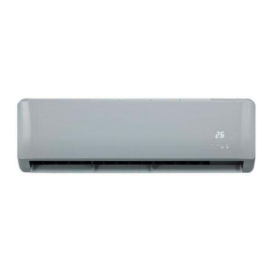
- Page 1 Wall Mounted Split Service manual CL23560 to CL23567 English www.mundoclima.com...
-
Page 2: Table Of Contents
The 2 Generation DC Series VRF Indoor Units Wall Mounted Split 1 Specifications ..................... 4 2 Dimensions ....................6 3 Unit Placement ..................7 4 Piping Diagram ................... 8 5 Wiring Diagram ..................9 6 Capacity Tables..................13 7 Electrical Characteristics ................21 8 Sound Levels .................... -
Page 3: Specifications
The 2 Generation DC Series VRF Indoor Units 1 Specifications Table 1.1: MVD-22(28,36,45)GDN1 specifications Model MVD-22GDN1 MVD-28GDN1 MVD-36GDN1 MVD-45GDN1 Power supply 1 phase, 220-240V, 50Hz Capacity Cooling kBtu/h 12.3 15.4 Power input Capacity Heating kBtu/h 10.9 13.6 17.1 Power input... - Page 4 The 2 Generation DC Series VRF Indoor Units Table 1.2: MVD-56(71,80,90)GDN1 specifications Model MVD-56GDN1 MVD-71GDN1 MVD-80GDN1 MVD-90GDN1 Power supply 1 phase, 220-240V, 50Hz Capacity Cooling kBtu/h 19.1 24.2 27.3 30.7 Power input 10.0 Capacity Heating kBtu/h 21.5 27.3 30.7 34.1 Power input Model ZKSP-58-8-1...
-
Page 5: Dimensions
The 2 Generation DC Series VRF Indoor Units 2 Dimensions 2.1 Unit Dimensions Figure 2.1: Wall mounted dimensions (unit: mm) MVD-22GDN1, MVD-28GDN1 MVD-36GDN1, MVD-45GDN1, MVD-56GDN1 MVD-71GDN1, MVD-80GDN1, MVD-90GDN1 201806... -
Page 6: Unit Placement
Short-circuit ventilation (where outlet air returns quickly to a unit’s air inlet) will not occur. 3.2 Space Requirements Figure 3.1: Wall mounted space requirements (unit: mm) MVD-22GDN1, MVD-28GDN1 MVD-36GDN1, MVD-45GDN1, MVD-56GDN1 Shape of indoor unit Shape of indoor unit... -
Page 7: Piping Diagram
The 2 Generation DC Series VRF Indoor Units 4 Piping Diagram Figure 4.1: Wall mounted piping diagram motor flare nut gas side heat exchanger flare nut liquid side Legend Indoor ambient temperature sensor Indoor heat exchanger mid-point temperature sensor Indoor heat exchanger outlet temperature sensor 201806... -
Page 8: Wiring Diagram
The 2 Generation DC Series VRF Indoor Units 5 Wiring Diagram Figure 5.1: 2.2/2.8kW Wall mounted wiring diagram Code Name Code Name Code Name Indoor fan motor Room temp. sensor Water level switch it h Swing motor Mid-pipe temp. sensor XP1-5/XS1-5 Connectors Electronic expansion valve... - Page 9 The 2 Generation DC Series VRF Indoor Units Figure 5.2: 3.6/4.5/5.6kW Wall mounted wiring diagram Code Name Code Name Code Name Indoor fan motor Room temp. sensor Water level switch Swing motor Mid-pipe temp. sensor XP1-5/XS1-5 Connectors Electronic expansion valve Outlet pipe temp.
- Page 10 The 2 Generation DC Series VRF Indoor Units Figure 5.3: 7.1/8.0/9.0kW Wall mounted wiring diagram Code Name Code Name Code Name Indoor fan motor Room temp. sensor Water level switch Swing motor Mid-pipe temp. sensor XP1-5/XS1-5 Connectors Electronic expansion valve Outlet pipe temp.
- Page 11 The 2 Generation DC Series VRF Indoor Units Notes for installers and service engineers Caution ƒ All installation, servicing and maintenance must be carried out by competent and suitably qualified, certified and accredited professionals and in accordance with all applicable legislation. ƒ...
-
Page 12: Capacity Tables
The 2 Generation DC Series VRF Indoor Units 6 Capacity Tables 6.1 Cooling Capacity Table Table 6.1: Wall mounted cooling capacity Indoor air temperature (°C WB/DB) Outdoor air Capacity 14/20 16/23 18/26 19/27 20/28 22/30 24/32 temperature (kW) (°C DB) 10.0 12.0 14.0... - Page 13 The 2 Generation DC Series VRF Indoor Units Table 6.1: Wall mounted cooling capacity (continued) Indoor air temperature (°C WB/DB) Outdoor air Capacity 14/20 16/23 18/26 19/27 20/28 22/30 24/32 temperature (kW) (°C DB) 10.0 12.0 14.0 16.0 18.0 20.0 21.0 23.0 25.0...
- Page 14 The 2 Generation DC Series VRF Indoor Units Table 6.1: Wall mounted cooling capacity (continued) Indoor air temperature (°C WB/DB) Outdoor air Capacity 14/20 16/23 18/26 19/27 20/28 22/30 24/32 temperature (kW) (°C DB) 10.0 12.0 14.0 16.0 18.0 20.0 21.0 23.0 25.0...
- Page 15 The 2 Generation DC Series VRF Indoor Units Table 6.1: Wall mounted cooling capacity (continued) Indoor air temperature (°C WB/DB) Outdoor air Capacity 14/20 16/23 18/26 19/27 20/28 22/30 24/32 temperature (kW) (°C DB) 10.0 10.4 12.0 10.2 14.0 10.2 16.0 10.0 18.0...
- Page 16 The 2 Generation DC Series VRF Indoor Units 6.2 Heating Capacity Table Table 6.2: Wall mounted heating capacity Indoor air temperature (°C DB) Outdoor air Capacity temperature (°C) (kW) -19.8 1.34 1.34 1.34 1.34 1.34 1.34 -18.8 1.44 1.44 1.44 1.44 1.44 1.44...
- Page 17 The 2 Generation DC Series VRF Indoor Units Table 6.2: Wall mounted heating capacity (continued) Indoor air temperature (°C DB) Outdoor air Capacity temperature (°C) (kW) -19.8 2.24 2.24 2.24 2.24 2.24 2.24 -18.8 2.40 2.40 2.40 2.40 2.40 2.40 -16.7 2.52 2.52...
- Page 18 The 2 Generation DC Series VRF Indoor Units Table 6.2: Wall mounted heating capacity (continued) Indoor air temperature (°C DB) Outdoor air Capacity temperature (°C) (kW) -19.8 3.53 3.53 3.53 3.53 3.53 3.53 -18.8 3.78 3.78 3.78 3.78 3.78 3.78 -16.7 3.97 3.97...
- Page 19 The 2 Generation DC Series VRF Indoor Units Table 6.2: Wall mounted heating capacity (continued) Indoor air temperature (°C DB) Outdoor air Capacity temperature (°C) (kW) -19.8 5.04 5.04 5.04 5.04 5.04 5.04 -18.8 5.40 5.40 5.40 5.40 5.40 5.40 -16.7 5.67 5.67...
-
Page 20: Electrical Characteristics
Generation DC Series VRF Indoor Units 7 Electrical Characteristics Table 7.1: Wall mounted electrical characteristics Power supply Indoor fan motors Model Rated motor Volts Min. volts Max. volts output (kW) MVD-22GDN1 220-240 0.32 0.02 0.25 MVD-28GDN1 220-240 0.32 0.02 0.25 MVD-36GDN1 220-240 0.45... -
Page 21: Sound Levels
The 2 Generation DC Series VRF Indoor Units 8 Sound Levels 8.1 Overall Table 8.1: Wall mounted sound pressure levels Sound pressure levels dB(A) Model name MVD-22GDN1 MVD-28GDN1 MVD-36GDN1 MVD-45GDN1 MVD-56GDN1 MVD-71GDN1 MVD-80GDN1 MVD-90GDN1 Notes: Sound pressure levels are measured in a semi-anechoic chamber. - Page 22 The 2 Generation DC Series VRF Indoor Units Figure 8.4: MVD-45GDN1 octave band levels Figure 8.5: MVD-56GDN1 octave band levels NC65 NC65 NC60 NC60 NC55 NC55 NC50 NC50 NC45 NC45 NC40 NC40 NC35 NC35 NC30 NC30 NC25 NC25 NC20 NC20 NC15 NC15 1000 2000 4000 8000...
-
Page 23: Error Codes
The 2 Generation DC Series VRF Indoor Units 9 Error codes With the exception of a mode conflict error, contact your supplier or service engineer if any of the error codes listed in the following table are displayed on the unit's display panel. If the mode conflict error is displayed and persists, contact your supplier or service engineer. These errors should only be investigated by a professional technician. - Page 24 ASK FOR MORE INFORMATION Phone: (+34) 93 446 27 80 eMail: info@mundoclima.com TECHNICAL ASSISTANCE Phone: (+34) 93 652 53 57 www.mundoclima.com...
Need help?
Do you have a question about the MVD-22GDN1 and is the answer not in the manual?
Questions and answers