
Related Manuals for Motorola ReaperHD


Summary of Contents for Motorola ReaperHD
- Page 1 Mobile LPR Hardware Installation Guide SEPTEMBER 2022 *MN009210A01* MN009210A01-AB © 2022 Motorola Solutions, Inc. All rights reserved...
-
Page 2: Legal And Support
License Rights The purchase of Motorola Solutions products shall not be deemed to grant either directly or by implication, estoppel or otherwise, any license under the copyrights, patents or patent applications of Motorola Solutions, except for the normal non-exclusive, royalty-free license to use that arises by operation of law in the sale of a product. -
Page 3: Contact Us
MN009210A01-AB Legal and Support 2022 Motorola Solutions, Inc. All Rights Reserved © Contact Us For inquiries, see https://www.motorolasolutions.com/en_us/support.html > License Plate Recognition (Vigilant) or contact our 24 hours support staff at: • Tel: 925-398-2079 • Fax: 925-398-2113 • Email: vigilantsupport@motorolasolutions.com... -
Page 4: Related Publication
MN009210A01-AB Related Publication Related Publication The following list contains part numbers and titles of related publications. To find and download the publications, visit https://learning.motorolasolutions.com. Part Number Title MN008501A01 Vigilant PlateSearch User Guide MN007806A01 Vigilant ClientPortal User Guide MN007809A01 Target Alert Service User Guide MN007802A01 Vigilant CarDetector Mobile User Guide... -
Page 5: Document History
MN009210A01-AB Document History Document History Version Description Date MN009210A01-AA Initial Release May 2022 MN009210A01-AB September 2022 • Added revised camera aiming and placement guide information. • Added kit contents and VLP/Tablet assembly in- formation. • Updated new example screenshots. -
Page 6: Table Of Contents
MN009210A01-AB Contents Contents Legal and Support.......................2 Intellectual Property and Regulatory Notices.................2 Contact Us............................. 3 Read Me First..........................3 Related Publication.....................4 Document History....................... 5 List of Figures......................8 List of Tables....................... 9 Chapter 1: Camera System Hardware Overview..........10 1.1 LPR Cameras........................10 1.2 VLP Camera System Kit...................... - Page 7 MN009210A01-AB Contents 5.1.5 Universal Ball Mount Camera Brackets..............47 5.2 Federal Signal Valor Light Bar Bracket..................49 5.3 Flat Cam Bracket........................50 Chapter 6: Parking Enforcement................52 6.1 VLS Mobile Tablet Assembly....................52 6.1.1 Assembling the VLS Mobile Tablet................52 6.2 Docking Station Assembly..................... 55 6.2.1 Assembling the Keyboard and the Ball Mount............
-
Page 8: List Of Figures
MN009210A01-AB List of Figures List of Figures Figure 1: VLP Processor Wiring Harness....................12 Figure 2: Wiring Harness to VLP Box.....................17 Figure 3: Ethernet Cable to VLP Box..................... 18 Figure 4: Camera Cable to VLP Processor.................... 18 Figure 5: GPS Cable to VLP Processor....................19 Figure 6: GPS Puck..........................19 Figure 7: On an Equipment Tray...................... -
Page 9: List Of Tables
MN009210A01-AB List of Tables List of Tables Table 1: Special Notations........................3 Table 2: Vigilant Mobile LPR Cameras....................10 Table 3: List of VLP Processor Equipment.....................11 Table 4: VLP Processor Wiring Harness Cable Color................12 Table 5: List of VLS Tablet Equipment....................13 Table 6: GPS Puck Connectors......................14 Table 7: M500 Cameras......................... -
Page 10: Chapter 1: Camera System Hardware Overview
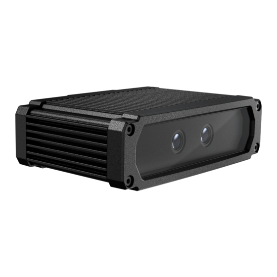
Table 2: Vigilant Mobile LPR Cameras Camera Photo ReaperHD VLP Camera System Kit The following is a list of the hardware components included with a VLP Processor Camera Kit. NOTE: This configuration also requires a connected Windows PC to run the CarDetector Mobile... -
Page 11: Table 3: List Of Vlp Processor Equipment
MN009210A01-AB Chapter 1 : Camera System Hardware Overview Table 3: List of VLP Processor Equipment Equipment Photo Camera and Magnet Mount Assembly Camera and Fixed Mount As- sembly VLP Processor Camera Cable... -
Page 12: Figure 1: Vlp Processor Wiring Harness
MN009210A01-AB Chapter 1 : Camera System Hardware Overview Equipment Photo VLP Processor Wiring Har- ness GPS Cable Figure 1: VLP Processor Wiring Harness Table 4: VLP Processor Wiring Harness Cable Color Color Description Black Ground +12 V Yellow Ignition IMPORTANT: Do not connect cameras when wet. Ensure that cable end and camera power port are dry to avoid damaging equipment. -
Page 13: Vls Mobile Tablet Camera System Kit
MN009210A01-AB Chapter 1 : Camera System Hardware Overview VLS Mobile Tablet Camera System Kit The following is a list of the hardware components included with a VLS Mobile Tablet Camera Kit. Table 5: List of VLS Tablet Equipment Equipment Photo Camera and Magnet Mount Assembly Camera PoE Injector... -
Page 14: Table 6: Gps Puck Connectors
MN009210A01-AB Chapter 1 : Camera System Hardware Overview Equipment Photo GPS Cable and Puck Table 6: GPS Puck Connectors Number Description GPS connector 4G connector Tablet... - Page 15 MN009210A01-AB Chapter 1 : Camera System Hardware Overview Equipment Photo Ram Mount Base Plate Ram Mount Pole Assembly...
- Page 16 MN009210A01-AB Chapter 1 : Camera System Hardware Overview Equipment Photo Tablet Docking Station Tablet KeyBoard/Mouse Kit Tablet Power Solution IMPORTANT: Do not connect cameras when wet. Ensure that cable end and camera power port are dry to avoid damaging equipment.
-
Page 17: M500 Camera System Kit
MN009210A01-AB Chapter 1 : Camera System Hardware Overview M500 Camera System Kit Table 7: M500 Cameras Equipment Photo M500 VLP Camera System Assembly Procedure: 1 To provide power, connect the wiring harness to the VLP Processor. Figure 2: Wiring Harness to VLP Box 2 Connect both ends of the Ethernet cable to the VLP Processor and a Windows PC respectively. -
Page 18: Figure 3: Ethernet Cable To Vlp Box
MN009210A01-AB Chapter 1 : Camera System Hardware Overview Figure 3: Ethernet Cable to VLP Box 3 Connect the camera cables to the PoE ports of the VLP Processor. Figure 4: Camera Cable to VLP Processor 4 Connect the GPS cable to the GPS port of the VLP Processor. NOTE: Ensure that the GPS puck is placed in a location with an unobstructed view of the sky, for example, at the dash of vehicle or exterior of vehicle. -
Page 19: Figure 5: Gps Cable To Vlp Processor
MN009210A01-AB Chapter 1 : Camera System Hardware Overview Figure 5: GPS Cable to VLP Processor Figure 6: GPS Puck Table 8: GPS Puck Number Description GPS Puck 5 For trunk installation, locate a suitable area for the VLP Processor so that the air can flow around outside of the enclosure. -
Page 20: Chapter 2: Vlp Installation
MN009210A01-AB Chapter 2 : VLP Installation Chapter 2 VLP Installation This section provides general guidelines and best practices for the VLP installation. Mounting the VLP Mount the VLP where the connections will be protected from damage and there is ample clearance for air to flow over the unit. -
Page 21: Figure 9: In Trunk Against The Prisoner Cage
MN009210A01-AB Chapter 2 : VLP Installation Figure 9: In Trunk Against the Prisoner Cage Wiring the VLP When running the power, network, GPS, and camera cables to the VLP, practice good cable management where possible and use cable ducting to protect the wiring. Standard 15 foot cables are provided, but longer 30' cables may be required for larger SUVs. -
Page 22: Figure 11: Vlp Cables
MN009210A01-AB Chapter 2 : VLP Installation Figure 11: VLP Cables Table 9: VLP Cables Description Number Name Description GPS Cable Connect the GPS antenna (puck) to the VLP. The GPS antenna is typically mounted on the dash- board of the vehicle using 3M Dual Lock fastener tape or directly on metal. - Page 23 MN009210A01-AB Chapter 2 : VLP Installation Number Name Description Cat5 Network Cable The cable runs from the LAN1 port on the VLP to the MDC/Laptop or docking station. The end cus- tomer may opt to plug into a local router/modem instead of the PC or docking station.
-
Page 24: Chapter 3: Camera Configurations
MN009210A01-AB Chapter 3 : Camera Configurations Chapter 3 Camera Configurations This section provides general guidelines and best practices for the cameras placement and installation. Take in to account the follow best practices for camera installation: • One lane per camera. •... -
Page 25: Camera Configuration Examples
Cameras should be positioned before you use the LPR scanning. • Cameras are selected based on the use case scenarios. • Use the CarDetector Mobile “Camera Aiming Tool” for aiming assistance. Mobile Camera Suitable Usage ReaperHD/L5M 6 mm Short Parking ReaperHD/L5M 8 mm Long Parking... - Page 26 MN009210A01-AB Chapter 3 : Camera Configurations Mobile Camera Suitable Usage ReaperHD/L5M 12 mm Short Traffic ReaperHD/L5M 16 mm Traffic ReaperHD/L5M 25 mm Long Traffic...
-
Page 27: Square Parked Car Scanning
MN009210A01-AB Chapter 3 : Camera Configurations 3.1.1 Square Parked Car Scanning This configuration is suitable for a short parking whether a perpendicular or angle parked cars. It is used for square parked cars such as in parking lots, shopping malls, and retail outlets. Figure 13: Perpendicular Parked Cars Capture Distance Camera model: L5M 6 mm (VSR-60-906) •... -
Page 28: Curb Parked Car Scanning
MN009210A01-AB Chapter 3 : Camera Configurations Camera model: RHD 6 mm (VSR-40-906) and RHD 8 mm (VSR-40-908) • Capture distance range: 6–24 ft and 8–36 ft. • Optimal capture distance: 12 ft and 16 ft (character height 45–50 px.) NOTE: Capture distances based on plate characters 69 mm tall. 3.1.3 Curb Parked Car Scanning This configuration is suitable for a short in traffic adjacent lane. -
Page 29: Curb Scanning-Radar Style
MN009210A01-AB Chapter 3 : Camera Configurations 3.1.4 Curb Scanning–Radar Style This configuration is suitable for a short in traffic adjacent lane or adjacent lane reversed. It is used for roadside scanning of moving traffic on rural or urban roads. Figure 16: In Traffic Adjacent Lane Capture Distance Camera model: L5M 16 mm (VSR-60-916) •... -
Page 30: Monitoring Divided Highways
MN009210A01-AB Chapter 3 : Camera Configurations Camera model: RHD 12 mm (VSR-40-912) and RHD 16 mm (VSR-40-916) • Capture distance range: 13–48 ft and 20–55 ft. • Optimal capture distance: 24 ft and 34 ft (character height 45–50 px.) NOTE: Capture distances based on plate characters 69 mm tall. 3.1.6 Monitoring Divided Highways This configuration is suitable for a long in traffic adjacent lane reversed or in traffic far lane. -
Page 31: Chapter 4: Camera Mounting
Camera Bracket Installation There are several options for mounting based on desired camera placement. NOTE: Never open or disassemble a camera. All ReaperSD, ReaperHD, and L5F/L5M cameras are nitrogen purged. Opening the camera will void the warranty. Figure 19: Universal Lightbar Bracket... -
Page 32: Camera Installation
MN009210A01-AB Chapter 4 : Camera Mounting Figure 21: Slick Top Roof Bracket Figure 22: Ball Mount Bracket Camera Installation Procedure: 1 Raise lightbar feet to their highest position to give the rear cameras room to angle downward. - Page 33 MN009210A01-AB Chapter 4 : Camera Mounting 2 Place cameras near the edge of the roof. NOTE: The roof will block the camera view if they are placed too far inboard. 3 Wedge the lightbar bracket between the lightbar and the lightbar foot so the cameras are near the edge of the roof.
- Page 34 MN009210A01-AB Chapter 4 : Camera Mounting 5 If needed, use the included spacers, or make custom spacers to give the cameras height above the roof, especially with low profile feet. Low profile feet do not allow rear cameras to tilt downward.
- Page 35 MN009210A01-AB Chapter 4 : Camera Mounting NOTE: Spacers are usually needed if the rear cameras can’t achieve a downward angle of 30°. 6 Use appropriate sized stabilizers (long and short included) and orient them properly to avoid obstructions. 7 Leave enough cable slack for the cameras to move freely left and right for angle adjustment.
- Page 36 MN009210A01-AB Chapter 4 : Camera Mounting 8 Install cameras right side up whenever possible (with the logo on the top and the Serial Number on the bottom).
- Page 37 MN009210A01-AB Chapter 4 : Camera Mounting NOTE: Ranger L5M and Reaper HD cameras can be mounted upside down if needed. Reaper SD cameras must always be right side up. 9 Always use dielectric grease in Reaper HD and SD camera connectors to prevent corrosion. NOTE: Ranger L5M cameras do not require grease.
-
Page 38: Chapter 5: Camera Brackets
MN009210A01-AB Chapter 5 : Camera Brackets Chapter 5 Camera Brackets Universal Light Bar Brackets These guidelines constitute best practices for the indicated light bar brand. There are two Universal Light Bar Bracket kits: VS-LBB-01-E LPR Camera Mounting Brackets - Light Bar Mounting Style - Single Bracket •... - Page 39 MN009210A01-AB Chapter 5 : Camera Brackets Low profile feet do not allow the rear cameras to tilt downwards. Adjusted feet should be raised to the highest position.
-
Page 40: Installing The Whelen Universal Light Bar Bracket
MN009210A01-AB Chapter 5 : Camera Brackets 5.1.1.1 Installing the Whelen Universal Light Bar Bracket Procedure: The following images show the typical Whelen install process. -
Page 41: Code3 Universal Light Bar Bracket
MN009210A01-AB Chapter 5 : Camera Brackets 5.1.2 Code3 Universal Light Bar Bracket The Universal LBB installs easily on a Code 3 Lightbar. Use the included spacer if the cameras need height off of the roof. With Spacer. -
Page 42: Soundoff Universal Light Bar Bracket
MN009210A01-AB Chapter 5 : Camera Brackets Without Spacer. 5.1.3 SoundOff Universal Light Bar Bracket The SoundOff Universal Light Bar Bracket requires drilling holes in the plastic spacer to match bolt pattern and replacing the stock 1/4-20 carriage bolts with longer 2-inch bolts. -
Page 43: Slick Top Camera Brackets
MN009210A01-AB Chapter 5 : Camera Brackets Figure 23: SoundOff Install Process 5.1.4 Slick Top Camera Brackets Slick top mounts are designed for specific vehicles or vehicle types and screw into the door jamb like a lightbar strap and have four strong magnet feet to secure it to the roof (no holes in roof required for bracket mounting). - Page 44 MN009210A01-AB Chapter 5 : Camera Brackets Slick top mounts can be installed on vehicles with or without a lightbar. Lip mount brackets secure to the trunk lip using magnet feet and tension screws on the lip.
-
Page 45: Ford Interceptor Suv Bracket Installation
MN009210A01-AB Chapter 5 : Camera Brackets 5.1.4.1 Ford Interceptor SUV Bracket Installation K-U-R-INTSUV-SET LPR Camera Mounting Brackets for Interceptor SUV Roof • Roof Mount Single LPR Camera Mounting Bracket - One per camera. K-U-R-INTSUV-20-SET LPR Camera Mounting Brackets for Interceptor SUV Roof - 2020+ •... -
Page 46: Chevrolet Tahoe Bracket Installation
MN009210A01-AB Chapter 5 : Camera Brackets 5.1.4.2 Chevrolet Tahoe Bracket Installation K-U-R-TAHOE-06-SET LPR Camera Mounting Kit for 2006–2014 Tahoe Roof • Roof Mount Single LPR Camera Mounting Bracket - One per camera. K-U-R-TAHOE-SET LPR Camera Mounting Kit for 2015+ Tahoe Roof •... -
Page 47: Universal Ball Mount Camera Brackets
MN009210A01-AB Chapter 5 : Camera Brackets 5.1.5 Universal Ball Mount Camera Brackets CAM-MOUNT-FLAT-ASSY-SET Universal LPR Camera Mounting Bracket • RAM ball mount with flat base. • Mounted directly to vehicle surface which requires drilling. • One bracket per camera. CAM-HITCH-SET Ramm Ball Set for trailers and covert installations. - Page 48 MN009210A01-AB Chapter 5 : Camera Brackets Push Bar camera mounting utilizes simple ball mount brackets.
-
Page 49: Federal Signal Valor Light Bar Bracket
MN009210A01-AB Chapter 5 : Camera Brackets Federal Signal Valor Light Bar Bracket FS-VBAR-LBB is a direct bolt in replacement for the stock lightbar feet. VS-LBB-FS-VBAR-02-A LPR Camera Mounting Brackets - For Federal Signal Valor Light Bar - Complete Set • LPR Camera Mounting Bracket - Rooftop under the light bar. -
Page 50: Flat Cam Bracket
MN009210A01-AB Chapter 5 : Camera Brackets Number Description Take-Down light relocation bracket Take-Down light extension cable Always install the individual camera brackets over the top of each camera. NOTE: Ensure that the camera serial number label is on bottom. Flat Cam Bracket There is not a vehicle-specific bracket available for all vehicle models. - Page 51 MN009210A01-AB Chapter 5 : Camera Brackets...
-
Page 52: Chapter 6: Parking Enforcement
MN009210A01-AB Chapter 6 : Parking Enforcement Chapter 6 Parking Enforcement VLS Mobile Tablet Assembly The Parking Enforcement Tablet and docking station utilizes a No-Drill Universal Laptop Mount that attaches to the front passenger seat floor bolts. The kit includes extra parts for different types of installs. Only use what is needed for the specific vehicle. -
Page 53: Figure 25: Camera Cable To Poe Injector
MN009210A01-AB Chapter 6 : Parking Enforcement Figure 25: Camera Cable to PoE Injector 4 Connect both of the GPS and 4G puck connectors to the Antenna GPS and LTE connectors of the VLS Mobile Tablet respectively. NOTE: The Antenna GPS and LTE connectors are located at the bottom of the VLS Mobile Tablet Docking Station. -
Page 54: Figure 27: 4G Connector To Vls Tablet Docking Station
MN009210A01-AB Chapter 6 : Parking Enforcement Figure 27: 4G Connector to VLS Tablet Docking Station 5 For vehicle installation, locate a suitable location for the PoE Injector such that the air can freely flow around outside of the enclosure. 6 Mount the PoE Injector using screws seated through the notches of the feet on both sides. NOTE: Ensure that the PoE Injector is fully secured to avoid unnecessary vibration while vehicle is traveling. -
Page 55: Docking Station Assembly
MN009210A01-AB Chapter 6 : Parking Enforcement Figure 29: Ram Mount Assembly Docking Station Assembly The VLS Mobile Tablet Docking Station assembly connects to a RAM Base Plate assembly to mount a VLS Mobile Tablet in a vehicle. The following images are the installation example of the docking station and tablet. -
Page 56: Table 11: Parts List (Included)
MN009210A01-AB Chapter 6 : Parking Enforcement The following parts are required to assemble the docking station. Table 11: Parts List (Included) Item Quantity RAM Keyboard Docking Cradle Double Socket Arm Mounting Plate Ball Mount with round base plate Ball Mount with square base plate Table 12: Hardware (Included) Item Quantity... -
Page 57: Assembling The Keyboard And The Ball Mount
MN009210A01-AB Chapter 6 : Parking Enforcement Table 13: Tools (Not Included) Item Phillips Head Screwdriver Adjustable Wrench 6.2.1 Assembling the Keyboard and the Ball Mount Procedure: 1 Turn the RAM Keyboard over so that the keys are facing downwards. - Page 58 MN009210A01-AB Chapter 6 : Parking Enforcement 2 Align the holes in a Ball Mount with round base plate with the four center screw holes in the middle of the keyboard.
-
Page 59: Assembling The Mounting Plate And The Ball Mount
MN009210A01-AB Chapter 6 : Parking Enforcement 3 Attach and tighten the Ball Mount by using the four Short Black Screw. 6.2.2 Assembling the Mounting Plate and the Ball Mount Procedure: 1 Orient the Mounting Plate so that when the wider end is flat against a surface, the narrow end is elevated. - Page 60 MN009210A01-AB Chapter 6 : Parking Enforcement 3 Insert a Long Black Screw into each screw hole and secure each screw with a Black Locking Nut. 4 Grip and tighten the nuts by using an adjustable wrench.
- Page 61 MN009210A01-AB Chapter 6 : Parking Enforcement...
-
Page 62: Assembling The Cradle And The Mounting Plate
MN009210A01-AB Chapter 6 : Parking Enforcement 6.2.3 Assembling the Cradle and the Mounting Plate Procedure: 1 With the Docking Cradle facing up, seat the Silver Locking Sleeve into one of the four unthreaded holes. 2 Insert Long Silver Screw through the Silver Locking Sleeve. - Page 63 MN009210A01-AB Chapter 6 : Parking Enforcement 3 Turn the Docking Cradle over while holding the screw in place. 4 Orient and align the mounting bracket over the screw.
- Page 64 MN009210A01-AB Chapter 6 : Parking Enforcement 5 Orient and align the Ball Mount with square base plate over the screw and mounting bracket. 6 Secure the assembly by tightening the Silver Nut on to the screw. 7 Insert the other three Silver Locking Sleeve and Long Silver Screw through the other three holes in the docking cradle as shown in step 1 step 2...
- Page 65 MN009210A01-AB Chapter 6 : Parking Enforcement 8 Check that the assembly is completed.
-
Page 66: Assembling The Keyboard And The Docking Cradle
MN009210A01-AB Chapter 6 : Parking Enforcement 6.2.4 Assembling the Keyboard and the Docking Cradle Procedure: 1 Loosen the clamp on the Double Socket Arm and seat one end over the ball mount on the docking cradle assembly. 2 Seat the ball mount of the keyboard assembly into the other end of the Double Socket Arm. - Page 67 MN009210A01-AB Chapter 6 : Parking Enforcement 3 Adjust the docking cradle and keyboard so that they are oriented as shown and tighten the clamp on the Double Socket Arm.
- Page 68 MN009210A01-AB Chapter 6 : Parking Enforcement 4 Plug the USB cable from the RAM Keyboard into one of the USB ports on the bottom of the Docking Cradle.
- Page 69 MN009210A01-AB Chapter 6 : Parking Enforcement The docking cradle assembly is now ready to be mounted on a RAM Base Plate vehicle mount and to accept a VLS Mobile Tablet.
- Page 70 MN009210A01-AB Chapter 6 : Parking Enforcement...
-
Page 71: Chapter 7: Covert Installations
MN009210A01-AB Covert Installations Chapter 7 Covert Installations Covert installations will always involve some level of customized installation and/or fabrication. It is common practice to hide the front cameras in the front grill or bumper and the rear cameras either inside the rear passenger cab (requires rolling down the windows) or in the bumper. NOTE: The installation must allow for proper adjustment of the camera angles. - Page 72 MN009210A01-AB Chapter 7 : Covert Installations Vigilant does not offer vehicle-specific brackets for covert installs. Basic ball mounts are typically provided for this purpose.
- Page 73 MN009210A01-AB Chapter 7 : Covert Installations To ensure that the camera angles are correct, it is best to contact your Customer Success Manager to arrange a technical discussion with a Field Service Engineer. Avoid costly mistakes like those shown here:...
Need help?
Do you have a question about the ReaperHD and is the answer not in the manual?
Questions and answers