
Related Manuals for Motorola IndigoVision UX-2MP-B-S


Summary of Contents for Motorola IndigoVision UX-2MP-B-S
- Page 1 Installation Guide IndigoVision UX Box Camera Models: UX-2MP-B-S UX-4MP-B-S UX-2MP-B-LT UX-4MP-B-T UX-8MP-B-S...
- Page 2 Document information This manual was created on Monday, March 8, 2021. Document ID: IU-FIX-MAN039-3 Legal considerations Laws that can vary from country to country may prohibit camera surveillance. Please ensure that the relevant laws are fully understood for the particular country or region in which you will be operating this equipment. IndigoVision Limited accepts no liability for improper or illegal use of this product.
- Page 3 Important Safety Information This manual provides installation and operation information and precautions for the use of this device. Incorrect installation could cause an unexpected fault. Before installing this equipment read this manual carefully. Please provide this manual to the owner of the equipment for future reference. This Warning symbol indicates the presence of dangerous voltage within and outside the product enclosure that may result in a risk of electric shock, serious injury or death to persons if proper precautions are not followed.
- Page 4 Use of controls or adjustments or performance of procedures other than those specified in this document may result in hazardous radiation exposure. If used outdoors, an approved outdoor mounting adapter or enclosure is required.
- Page 5 Regulatory Notices This device complies with part 15 of the FCC Rules. Operation is subject to the following two conditions: (1) this device may not cause harmful interference, and (2) this device must accept any interference received, including interference that may cause undesired operation. This Class B digital apparatus complies with Canadian ICES-003.
-
Page 6: Table Of Contents
Table of Contents Overview Front View Rear View Installation Required Tools and Materials Camera Package Contents Installation Steps Mounting the Camera Connecting Cables Initializing a Camera Username and Password Assigning an IP Address Accessing the Live Video Stream Aiming and Focusing the Camera (Optional) Configuring SD Card Storage Configuring the Camera For More Information... -
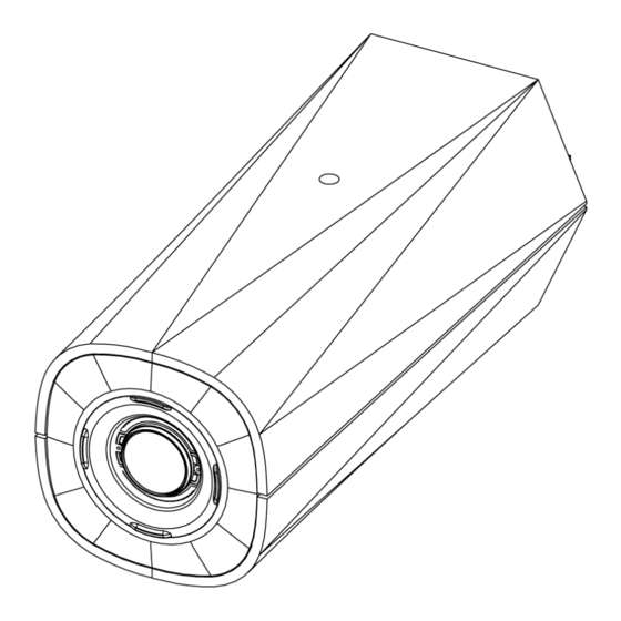
Page 7: Overview
Overview Front View 1. Camera mounts Provides mounting points for the camera. Mounts accept 1/4”-20 x 5/16" max thread UNC bolts commonly found on tripods and mounting brackets. 2. Serial number tag Device information, product serial number and part number label. Overview... -
Page 8: Rear View
Rear View 1. I/O connector block Provides connections to external input/output devices. 2. Audio/video connector Accepts a mini-jack connector (3.5 mm). 3. Connection status LED indicator Provides information about device operation. For more information, see Connection Status LED Indicator on page 11. - Page 9 required when Power over Ethernet is not available. 7. SD card slot Accepts an SD card for onboard storage. Rear View...
-
Page 10: Installation
Installation Required Tools and Materials Small slotted screwdriver with 5/64” or 2 mm blade width — for connecting power when not using Power over Ethernet. Mounting bracket, enclosure or tripod. Camera Package Contents IndigoVision UX Box Camera Installation Steps Complete the following sections to install the device. Mounting the Camera Camera mounting points are provided on both the top and bottom of the camera body. -
Page 11: Initializing A Camera Username And Password
For more information see Connecting to Microphones, Speakers, and Video Monitors on page 9. 4. Connect power using one of the following methods: Power over Ethernet (PoE) Class 3 — If PoE is available, the LEDs will turn on. External Power — Connect an external 12 V DC or 24 V AC power source to the power connector block. 5. -
Page 12: Accessing The Live Video Stream
Note: Cameras do not have a default username or password and will be in a factory default state. You must create a user with administrator privileges before the camera is operational. For more information, see Initializing a Camera Username and Password on the previous page. -
Page 13: For More Information
If you have installed multiple cameras, you can use the Camera Configuration Tool to configure common settings. For more information, see the help section built into the Camera Configuration Tool. If the camera is connected to Control Center, you can use the client software to configure the camera. For more information, see the IndigoVision Control Center Online Help. -
Page 14: Cable Connections
Cable Connections Connecting External Power If PoE is not available, the camera needs to be powered through the removable power connector block. Refer to the diagrams in this guide for the location of the power connector block. The power consumption information is listed in the product specifications. To connect power to the power connector block, complete the following steps: 1. -
Page 15: Connecting To Microphones, Speakers, And Video Monitors
Figure 1: Example application. 1. Ground 2. Relay Input — To activate, connect the Input to the Ground pin. To deactivate, leave disconnected or apply between 3-15 V. 3. Relay Output — When active, Output is internally connected with the Ground pin. Circuit is open when inactive. Maximum load is 25 VDC, 120 mA. - Page 16 Note: The camera only supports line level mono audio input and an NTSC or PAL video output. The video output signal is determined by the camera flicker control setting. When the camera flicker control is set to 60 Hz, the video output signal is NTSC. When the flicker control is set to 50 Hz, the video output signal is PAL. Use the Camera Installation Tool to configure the camera’s flicker control in the Image and Display setup.
-
Page 17: Connection Status Led Indicator
Connection Status LED Indicator Once connected to the network, the Connection Status LED indicator will display the progress in connecting to the Network Video Management software. The following table describes what the LED indicator shows: Connection State Connection Status Description LED Indicator Obtaining IP Address One short flash every... -
Page 18: Resetting To Factory Default Settings
Resetting to Factory Default Settings If the device no longer functions as expected, you can choose to reset the device to its factory default settings. Use the firmware revert button to reset the device. The firmware revert button is shown in the following diagram: For models that feature an SD card slot, resetting the camera will not affect video that has been recorded to the SD card. -
Page 19: Setting The Ip Address Using The Arp/Ping Method
Setting the IP Address Using the ARP/Ping Method Complete the following steps to configure the camera to use a specific IP address: Note: The ARP/Ping Method will not work if the Disable setting static IP address through ARP/Ping method checkbox is selected in the camera's web browser interface. For more information, see the IndigoVision Camera Web Interface User Guide.
Need help?
Do you have a question about the IndigoVision UX-2MP-B-S and is the answer not in the manual?
Questions and answers