Table of Contents
Advertisement
Quick Links
OPERATOR MANUAL
IMPORTANT INFORMATION, KEEP FOR OPERATOR
This manual provides information for:
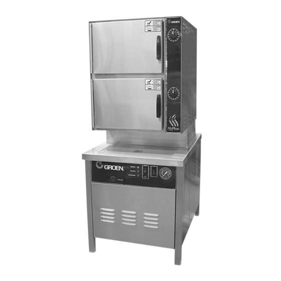
MODEL HY-PLUS-SE
ATMOSPHERIC
CONVECTION STEAMER ON A
ELECTRIC BOILER BASE
· For Models: HY-6SE and HY-10SE
· Capacity: 6 or 10 Steamer Pans (12" x 20" x 2-1/2")
THIS MANUAL MUST BE RETAINED FOR FUTURE REFERENCE. READ, UNDERSTAND
AND FOLLOW THE INSTRUCTIONS AND WARNINGS CONTAINED IN THIS MANUAL.
WARNING / FOR YOUR SAFETY
Do not store or use gasoline or other flammable vapors and liquids in
the vicinity of this or any other appliance.
WARNING
Improper installation, adjustment, alteration, service or maintenance
can cause property damage, injury or death. Read the installation,
operating and maintenance instructions thoroughly before installing
or servicing this equipment.
NOTIFY CARRIER OF DAMAGE AT ONCE
It is the responsibility of the consignee to inspect the container upon receipt of same and to deter-
mine the possibility of any damage, including concealed damage. Groen suggests that if you are
suspicious of damage to make a notation on the delivery receipt. It will be the responsibility of the
consignee to file a claim with the carrier. We recommend that you do so at once.
Manufacture Service/Questions 888-994-7636.
Information contained in this document is known to be current and accurate at the time of printing/creation.
Reference our product line website for the most updated product information and specifications.
© 2023 Electrolux Professional, Inc. All Rights Reserved.
PART NUMBER 162102 REV B (09/23)
888-994-7636, fax 888-864-7636
unifiedbrands.net
Advertisement
Table of Contents

Related Manuals for Groen HY-PLUS-SE


Summary of Contents for Groen HY-PLUS-SE
- Page 1 It is the responsibility of the consignee to inspect the container upon receipt of same and to deter- mine the possibility of any damage, including concealed damage. Groen suggests that if you are suspicious of damage to make a notation on the delivery receipt. It will be the responsibility of the consignee to file a claim with the carrier.
- Page 2 THIS MANUAL MUST BE RETAINED FOR FUTURE REFERENCE. READ, UNDERSTAND AND FOLLOW THE INSTRUCTIONS AND WARNINGS CONTAINED IN THIS MANUAL. FOR YOUR SAFETY DO NOT STORE OR USE GASOLINE OR OTHER FLAMMABLE VAPORS AND LIQUIDS IN THE VICINITY OF THIS OR ANY OTHER APPLIANCE.
- Page 3 IMPORTANT - READ FIRST - IMPORTANT WARNING: THE UNIT MUST BE INSTALLED BY PERSONNEL QUALIFIED TO WORK WITH ELECTRICITY AND PLUMBING. IMPROPER INSTALLATION CAN CAUSE INJURY TO PERSONNEL AND/OR DAMAGE TO THE EQUIPMENT. INSTALLATION MUST COMPLY WITH APPLICABLE CODES. NOTICE: DO NOT INSTALL THE UNIT IN ANY WAY WHICH WILL BLOC K THE RIGHT SIDE VENTS , OR WITHIN 12 INCHES OF A HEAT SOURCE SUCH AS A BRAISING PAN , DEEP FRYER , CHAR BROILER OR CONVECTION OVEN.
- Page 4 IMPORTANT - READ FIRST - IMPORTANT WARNING: DO NOT EXPOSE SKIN TO ESCAPING STEAM. SEVERE BURNS CAN RESULT. CAUTION: MAKING ANY ELECTRICAL OR MECHANICAL CHANGE IN THE UNIT WITHOUT PRIOR WRITTEN APPROVAL FROM ENGINEERING WILL VOID ALL WARRANTIES. WARNING: ALL POTENTIAL USERS OF THE EQUIPMENT SHOULD BE TRAINED IN SAFE AND CORRECT OPERATING PROCEDURES. WARNING: DO NOT OPERATE THE UNIT UNLESS ALL REMOVABLE PANELS (RIGHT, LEFT, FRONT AND REAR) HAVE BEEN PROPERLY INSTALLED.
-
Page 5: Equipment Description
Equipment Description WARNING The HY-SE Steamer is designed to bring you years of service. It has two stainless steel THE UNIT MUST BE INSTALLED BY cavities (cooking chambers) and a control compartment, which houses the electrical PERSONNEL WHO ARE QUALIFIED TO WORK components and steam valves. -
Page 6: Water Quality & Treatment
Water Quality & Treatment REDUCE SCALE PROBLEMS BY USING It is essential that the boiler be supplied with water that will not form scale at an AND MAINTAINING A WATER SOFTENER unacceptable rate. The boiler was engineered to minimize scale, but its formation FOR YOUR STEAMER! depends on water hardness and how much the unit is used. -
Page 7: Installation
Installation WARNING WHEN THE UNIT IS RECEIVED, IMMEDIATELY INSPECT IT FOR EXTERNAL OR INTERNAL MAKING ANY ELECTRICAL OR MECHANICAL DAMAGE. REPORT ANY DAMAGE TO THE FREIGHT CARRIER. After inspection, keep the CHANGE IN THE UNIT WITHOUT PRIOR unit in its shipping container until it is installed. It can be installed on combustible and APPROVAL WILL VOID ALL WARRANTIES. - Page 8 Installation WARNING Water Connection THE UNIT MUST BE INSTALLED BY Cold water is supplied via a 1/2” NPT pipe connection at the rear of the PERSONNEL WHO ARE QUALIFIED TO unit. A check valve (back siphonage device) must be installed in accord WORK WITH ELECTRICITY AND PLUMBING.
- Page 9 Installation Utility Connections Cold water (untreated). Cold water (treated). Hot water (for faucet on 36” and wider units with kettles). Steam outlet (for power take-off). Not used. Drain (for boiler, steamers and condenser spray). Also for kettle condensate and sink where used. Electrical (conduit through underside, terminals at the right on the inside).
-
Page 10: Initial Start-Up
Initial Start-Up After the unit has been installed, test it to ensure that it is operating properly. Remove literature and packing material from the interior and exterior of the unit. Make certain the water supply is turned on. Turn on electrical power to the unit. Turn the on/off switch on the cabinet front panel to the “ON”... -
Page 11: Operation
Operation WARNING Controls ALL POTENTIAL USERS OF THE EQUIPMENT Operating controls are located on the front panel of the unit. SHOULD BE TRAINED IN SAFE AND CORRECT The on/off switch starts the unit or shuts it off. OPERATING PROCEDURES. The RESET indicator lights to show that the boiler has filled with water and that the heater element contactors can close. - Page 12 Operation WARNING Operating Procedure ANY POTENTIAL USER OF THE EQUIPMENT SHOULD BE TRAINED IN SAFE AND CORRECT Turn on the water supply to the unit. OPERATING PROCEDURES. Turn on electrical power to the unit. WARNING Turn the on/off switch on the front of the cabinet to “ON.” WHEN YOU OPEN THE DOOR, STAY AWAY FROM THE STEAM COMING OUT OF THE The boiler drain valve will close and the unit will fill with water.
-
Page 13: Sequence Of Operation
Sequence of Operation CAUTION When electrical power is turned on to the unit, the following happens: ESCAPING STEAM MAY CAUSE SEVER • The drain valve closes BURNS. STAY AWAY FROM THERMOSTATIC • The water valve opens AIR VENT AND PRESSURE RELIEF VALVES. •... - Page 14 Steamer Compartment Cleaning WARNING To keep your Steamer in proper working condition, clean the unit each day. This DISCONNECT THE POWER SUPPLY BEFORE regular cleaning will reduce the effort required to clean the cavities. CLEANING THE OUTSIDE OF THE STEAMER. Suggested Tools KEEP WATER AND CLEANING SOLUTIONS OUT OF CONTROLS AND ELECTRICAL...
-
Page 15: Boiler Cleaning
Boiler Cleaning WARNING Whenever the boiler is turned off and allowed to cool to about 130ºF, it drains auto- WATER AND VALVES MAY BE VERY HOT, matically. This should be done every day to minimize scale buildup inside the boiler. AND MAY CAUSE BURNS. - Page 16 Cleaning WARNING 13. Set steamer timers for 10 minutes. SOLUTION AND VALVES WILL BE VERY HOT, AND MAY CAUSE BURNS. PROTECT HANDS 14. When steamer timers sound, turn them to OFF and open the doors. FROM HOT SURFACES AND CONTINUE TO USE PROTECTIVE GLOVES.
- Page 17 Steamer Maintenance The Steamer is designed for minimum maintenance, and no user adjustments should WARNING be necessary. Certain parts may need replacement after prolonged use. If there is a BEFORE REPLACING ANY PART TURN OFF need for service, only Authorized Service Representatives should do the work. THE ELECTRICAL POWER TO THE UNIT.
-
Page 18: Maintenance
Maintenance WARNING Your boiler is designed to minimize maintenance, but certain parts may need to USE ONLY MANUFACTURER-SUPPLIED PARTS. be replaced after prolonged use. For the most part, no user adjustments should be USING SUBSTITUTE, UNAUTHORIZED OR necessary. If a need for service arises, only Authorized Representatives should perform “GENERIC”... -
Page 19: Troubleshooting
Troubleshooting Do not operate the unit if it malfunctions or has damaged or broken parts. Steam boilers are designed to operate smoothly and ef- ficiently when maintained properly. However, the following is a list of checks to make if there is a problem. Electrical schematics are provided in this manual, and inside the unit electrical enclosure. - Page 20 Troubleshooting SYMPTOM WHAT TO CHECK Boiler builds pressure but User a. Is the water level below the “mid” water level probe? Verify that the water shuts down. RESET light supply is sufficient to maintain the water level at or above the “mid” water level comes on.
-
Page 21: Parts List
Parts List Steamer Cavity OM-HY-SE... - Page 22 Parts List Steamer Cavity Description Part # Description Part # UPPER CAVITY DRAIN HOSE 088847 BRACKET, TRANSFORMER MTG - SE - 480V 102287 MOTOR ASSEMBLY 096740 RUBBER PAD - SE - 480V 102292 TIMER 096826 TRANSFORMER, 230V - SE - 480V 101111 KNOB, TIMER 123100...
- Page 23 Parts List Motor/Fan Assembly Description Part # MOTOR 096739 SLINGER WASHER 096831 MOTOR MOUNTING PLATE 094134 SHAFT SEAL 096868 PLATE SEAL HOLDER 096752 OM-HY-SE...
- Page 24 Parts List Sheet Metal & Doors Description Part # COVER, RIGHT SIDE (6-PAN) 143778 COVER, RIGHT SIDE (10-PAN) 159866 COVER, LEFT SIDE (6-PAN) 123184 COVER, LEFT SIDE (10-PAN) 159867 COVER ASSEMBLY, TOP 123182 SCREW, 10-32 X 3/8 TRUSS 004173 HEAD RETAINER, TOP 123156 SCREW, 8-32 X 3/8 SLOT-...
- Page 25 Parts List Door & Cavity Hardware Description Part # DOOR GASKET (6-PAN) 094147 DOOR GASKET (10-PAN) 125907 DOOR HANDLE 070123 DOOR CAM 074252 MAGNET ASSEMBLY 069762 U-CHANNEL ASSY. (6- 094144 PAN) (INCL. DOOR SPRING 078911) U-CHANNEL ASSY. (10- 125925 PAN) (INCL. DOOR SPRING 078911) LATCH SPRING 078911...
- Page 26 Parts List Drain Box w/Spray Condenser Description Part # SOLENOID VALVE (SPRAY 099221 CONDENSER) HOSE D “ ID X 8” LONG 099282B RUBBER FLAP 099213 SPACER 099212 HOSE, OUTLET 1 “ID X 3” 099280B LONG ANCHOR COUPLING, D” NPT N89267 OM-HY-SE...
- Page 27 Parts List Boiler Electrical Controls Description Part # WATER LEVEL BOARD, SINGLE 122192 WATER LEVEL BOARD, DOUBLE 116016 TRANSFORMER 208/240V 121716 PRIMARY/24V SECONDARY, 75VA CONTACTOR 148102 FUSEHOLDER 096809 FUSE 071489 GROUND TERMINAL 119829 TERMINAL BLOCK 99295 LIGHT AMBER 116384 LIGHT RED 116383 LAMP RESET 099289...
-
Page 28: Electrical Schematic
Electrical Schematic Steamer Cavities OM-HY-SE... - Page 29 Electrical Schematic Boiler OM-HY-SE...
-
Page 30: Service Log
Service Log Model No: Purchased From: Serial No: Location: Date Purchased: Date Installed: Purchase Order No: For Service Call: Date Maintenance Performed Performed By OM-HY-SE...
Need help?
Do you have a question about the HY-PLUS-SE and is the answer not in the manual?
Questions and answers