
Related Manuals for Siemens SITRANS FM100


Summary of Contents for Siemens SITRANS FM100
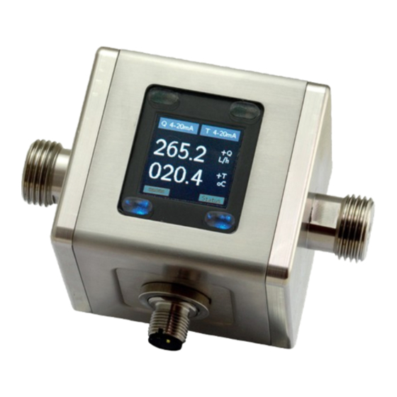
- Page 1 Edition 10/2021 OPERATING INSTRUCTIONS SITRANS F Electromagnetic flowmeters SITRANS FM100 www.siemens.com...
-
Page 2: Table Of Contents
We don’t accept warranty and liability claims neither upon this publication nor in case of improper treatment of the described products. The document may contain technical inaccuracies and typographical errors. The content will be revised on a regular basis. These changes will be implemented in later versions. - Page 3 SITRANS FM100 Dimensions ....................47 Product documentation and support ............48 16.1 Product documentation ..............48 16.2 Technical support ................49 Appendix ..................... 50 17.1 IO-Link process data structure ............50 ...
-
Page 4: Note
SITRANS FM100 2. Note Please read these operating instructions before unpacking and putting the unit into operation. Follow the instructions precisely as described herein. The devices are only to be used, maintained and serviced by persons familiar with these operating instructions and in accordance with local regulations applying to Health &... -
Page 5: Instrument Inspection
SITRANS FM100 3. Instrument Inspection Instruments are inspected before shipping and sent out in perfect condition. Should damage to a device be visible, we recommend a thorough inspection of the delivery packaging. In case of damage, please inform your parcel service / forwarding agent immediately, since they are responsible for damages during transit. -
Page 6: Operating Principle
SITRANS FM100 6. Operating principle 6.1 General The new Siemens SITRANS FM100 Flowmeter is designed to measure and monitor small and medium flows of conductive fluids in piping. The device works on the magnetic-inductive measuring principle. According to Faraday's law of induction, a voltage is induced in a conductor moving in a magnetic field. -
Page 7: Check Operating Conditions
SITRANS FM100 7.1 Check operating conditions flow rate max. operating pressure max. operating temperature In general, FM100 is subjected to the same loads as the piping into which it is installed. The FM100 should therefore be kept away from extreme loads, such as pressure surges with strong, dynamic pipe movements, vibrations in the proximity of centrifugal pumps, high temperature media, flooding etc. - Page 8 SITRANS FM100 Inlet and outlet run Installation from top to bottom avoid these installation locations Gas bubbles, particle Free outlet A5E48762204-AB page 7...
-
Page 9: Electrical Connection
SITRANS FM100 8. Electrical Connection 8.1 General Attention! Make sure that the voltage values of your system correspond with the voltage values of the measuring unit. Make sure that the supply wires are de-energised. Connect the supply voltage and the output signal to the plug PIN’s as stated below. -
Page 10: Pin Assignment
SITRANS FM100 8.2 Pin assignment 8.2.1 External connection with electrical connector M12x1 4-pin A5E48762204-AB page 9... -
Page 11: Connection Example Outputs
SITRANS FM100 8.3 Connection example outputs: OUT2: analogue output 4-20 mA OUT1: analogue output 0-10 V Configurable output functions: Out 1 Out 2 analogue output 4-20 mA analogue output 4-20 mA analogue output 0-20 mA analogue output 0-20 mA analogue output 2-10 V... -
Page 12: Operation And Menu Structure
SITRANS FM100 9. Operation and menu structure 9.1 General 9.1.1 Operation of the optical buttons Deactive optical button Optical button active An optical button is located at each corner of the TFT display. The operability of the respective buttons is signaled by blue backlighting; therefore non-backlit buttons are disabled and cannot be operated. -
Page 13: Measuring Mode
SITRANS FM100 function key symbol designation Measuring mode menu mode value input Menu level lower / forward forward (last menu level: Save value) Menu function: menu backward level higher / back (last step: exit menu) 9.2 Measuring mode After applying the supply voltage, the device starts in measuring mode. In this mode, the measured values of the respective measuring variables are continuously recorded;... - Page 14 SITRANS FM100 Measurement Mode Display Layout 'Single' The measurement variables are represented by their corresponding symbols: Mesuring variables Menu entry Description Symbol Flow Flow rate Volume Accumulated totalizer Temperature Medium temperature Part volume Partial totalizer The outputs and their status are shown on the display as follows:...
- Page 15 SITRANS FM100 Measurement Mode Display Layout 'Dual' Out 1 configured as switching output Out 2 configured as analogue output 4-20 mA pushpull and assigned to flow and assigned to temperature Font white: MV within MR Measuring variables with sign for direction Font yellow: 100% MR <=MV <=OverFlow...
-
Page 16: Menu Mode
SITRANS FM100 9.3 Menu Mode In menu mode, all device parameters can be set. The individual parameters are arranged in menu groups by function. While the menu mode is activated, the signal processing and the outputs are still active in the background. However, all display parameters and outputs are updated after exiting the menu mode or in the measuring mode. -
Page 17: Device Configuration
The flowmeter FM100 is pre-configured in factory. Changing the parameters "Measuring range" and "Sensor constant" or "K factor" is therefore not permitted. The adjustment of these parameters is only possible on the part of Siemens - factory. In the event of subsequent changes to volume or throughput units, the dependent parameters are converted and adjusted accordingly. -
Page 18: Display
SITRANS FM100 10.3 Display 10.3.1 Refresh Parameter "Refresh" defines the time interval within which the measuring variables are displayed. The "Refreshrate" can be increased in steps of 0.5 sec. to 10 sec. An increase in the refresh rate time causes an increased "filtering" of the display value. - Page 19 SITRANS FM100 The called hotkey function remains permanently activated and can only be left by pressing the key . A direct reset function is available for the MIN / MAX measured value function and the partial quantity counter. 10.3.6 Key sensitivity The sensitivity of the keys can be adjusted by setting the key sensitivity.
-
Page 20: Measurement
SITRANS FM100 Parameter table Display Sub- Sub- Sub- Default Default Parameter para- para- para- Value range/ Sublevel Description value value level meter meter meter value list level 1 level 2 level 3 Sets the display refresh Refresh value input 0.5-10 sec 0.5 sec... - Page 21 SITRANS FM100 10.4.1 Flow 10.4.1.1 Unit The displayed unit for the flow measurement can be selected from various predefined standard units. It is also possible to define a user-defined unit ("user"), here the "user unit" must be in LPM (liters / min.) be programmed: e.g.
- Page 22 SITRANS FM100 10.4.2.2 Unit of the total volume counter The parameter "Unit" determines the volume unit of the total volume counter. The listed volume units are available. When changing the volume unit, the current counter reading is converted to the new volume unit.
- Page 23 SITRANS FM100 Volume flow, temperature and part quantity counter The simulation starts as soon as the simulation is activated and the setting menu is exited. The simulation is interrupted or stopped, if the setting menu is called up. There are 3 different simulation types available for each purpose: a.) „Triangle“...
-
Page 24: Dosing Function
SITRANS FM100 Parameter table Measuring Sublevel Para- Subpara- Sub- Sub- Description Value range/ Default Default meter meter level para- para- value list value value level meter meter level 2 level 3 L/m, L/h, m3/h, galUS/m, galUS/h, galUs/ Unit List selection... - Page 25 SITRANS FM100 The different output types are optimized for different types of applications. The following table contains the application recommendations for the different output types. If the outputs are not used according to the recommendations, measurement deviations can occur and the desired functionality is not achieved.
- Page 26 SITRANS FM100 10.6.1.2 Output type The parameter "Output type" defines the function of the transistor output. NPN, PNP or PP (push-pull) output types are available. The push-pull type combines NPN and PNP and is therefore the best choice for most circuits. All outputs are short circuit and overload protected.
- Page 27 SITRANS FM100 10.6.1.7 Filter factor (delay) Further suppression of the switching outputs of fluctuating measuring signals can be achieved by setting the parameter "Filter factor". If this parameter is selected greater than 0, the switching of the output will be delayed accordingly. The "Supp direction"...
- Page 28 SITRANS FM100 10.6.2 Analogue outputs 10.6.2.1 Current output 0(4)-20 mA The current output gives a measured variable (flow or temperature) in scaled form as a 0 (4) -20 mA current signal. The current output is scaled via the "Value 20 mA "and" Value 4 mA "(with current output 0-20 mA "Value 0 mA").
- Page 29 SITRANS FM100 Output behaviour 0-20 mA and 0-10 V 10.6.2.3 Activation of behaviour according to NAMUR recommendation NE43 For all analogue outputs (current and voltage), the output behaviour can be activated according to NAMUR recommendation NE43. When the function is activated, e.g.
- Page 30 SITRANS FM100 The electrical output type of the pulse output is push-pull, therefore HIGH and LOW are actively switched through at the output. Behavior on OVERFLOW: If the volumetric flow measurement is in the OVERFLOW range, the pulse output is switched off and a constant HIGH level is applied to the output.
- Page 31 SITRANS FM100 Measuring pulse width min. pulse max. pulse rate range [LPM] [ms] volume [L] [pulse/L] 20 0.08889 11.25 10 0.04444 22.50 100 5 0.02222 45.00 1 0.00444 225.00 20 0.04444 22.50 10 0.02222 45.00 50 5 0.01111 90.00 1 0.00222 450.00 20 0.02222 45.00 10 ...
- Page 32 SITRANS FM100 10.6.4 Frequency output The FM100 flowmeter provides a scalable frequency output. When this output is activated, the measurement variable (flow or temperature) associated with the frequency output is output proportionally as a frequency with a 1: 1 pulse / pause duration.
- Page 33 SITRANS FM100 Parameter table Output 1/2 – Flow Sub- Sub- Sub-parameter Value range / Standard Standard parameter parameter Description level 1 value list value LPM value GPM level 2 level 3 disabled Output deactivated IO-Link Limit function / Function Sets the basic function...
- Page 34 SITRANS FM100 Sub- Sub- Sub-parameter Value range / Standard Standard parameter parameter Description level 1 value list value LPM value GPM level 2 level 3 Frequency output at max. frequency 50-1000 Hz 500 Hz "value at max. Hz" Overflow value in % of...
- Page 35 SITRANS FM100 Parameter table Output 1/2 – Temperature Sub- Sub- Sub- Value range / Standard Standard parameter parameter parameter Description value list value LPM value GPM level 1 level 2 level 3 disabled Output deactivated disabled Sets the basic Limit function / window...
-
Page 36: User Service
SITRANS FM100 Parameter table Output 1/2 – Part volume Sub- Sub- Sub- Standard Value range / Standard parameter parameter parameter Description value value list value LPM level 1 level 2 level 3 Disabled Output deactivated disabled Sets the Pulse ml, L, m3,... -
Page 37: Service / Factory Service
SITRANS FM100 Parameter table User menu Standard Parameter Value range / Standard Sublevel Description value level value list value LPM Protects the user service Password value input menu by password prompting 00000-99999 00000 if the password is not "00000" Resets the device to factory... -
Page 38: Device Default Settings
SITRANS FM100 Parameter table Info Menu Sublevel Description level General Displays the measuring ranges of the device Version Displays the hardware and software version Info Manual Displays the QR code to download the instruction manual 10.10 Device default settings The FM100 flowmeter is factory set and unloaded with the following configuration:... -
Page 39: Status
SITRANS FM100 11. Status The electromagnetic flowmeter can detect and display various device or application errors. If there is a status or error message, the STATUS symbol in the display alternately flashes orange / red. To call up the status / error information, the status key must be pressed, then the status window that appears then lists all the messages that have accumulated up to this point in time. -
Page 40: Dosing Function
SITRANS FM100 12. Dosing function The standard FM100 provides a simple dosing function. This can be permanently activated or deactivated in the settings menu under the menu item "dosing". If the dosing function is activated, fixed functions are assigned to the 2 outputs which... - Page 41 SITRANS FM100 Control input: Connection OUT1 can be used as a control input for the functions Start / Stop / Reset when the dosing function is activated. Function Conditions Control pulsetime START Stop Modus 0.5 s < t < 4 s...
- Page 42 SITRANS FM100 Description of dosing parameters Dosing quantity "Value" Parameter "Value" determines the dosing volume. The volume unit is specified in the "Unit" parameter. The maximum size is limited to 9999.9 (one digit after the decimal point). The absolute quantity can be extended or restricted by a suitable choice of dosing unit.
- Page 43 SITRANS FM100 Parameter table Dosing Subpara- Subpara- Subpara- Standard Parameter Value range / Standard Sublevel meter meter meter Description value level value list value LPM level 1 level 2 level 3 Dosing function disabled deactivated disabled Dosing function Activation activated Value 0 ≤...
-
Page 44: Io-Link Function
SITRANS FM100 13. IO-Link function As of firmware version REV190320, the FM100 flowmeter has an IO-Link communication interface as standard. Process and diagnostic data can be accessed directly via this interface and the device can be parameterized. Output 1 is factory configured for IO-Link function. If the IO-Link communication mode is active, the "IOLINK"... -
Page 45: Technical Information
SITRANS FM100 14. Technical Information Measurement process: electromagnetic Range: see order details Media: conductive fluids Minimum conductivity: ≥20 µS/cm 70 mm 2 /s Max. medium viscosity: Max. pressure: 16 bar Accuracy: <±(0.8% of reading+ 0.5% of full scale)* Repeatability: ±0.2% of full scale... - Page 46 SITRANS FM100 15 VDC <UHigh <Vs Total and partial quantity counter: overflow (reset) at 15 * 10 liters (regardless of the set unit) Electrical connection: plug M12x1, 4-pin Dosing Function Dosing value: 0.1 …9999.9 [Unit] Dosing output OUT2 PushPull, High active...
- Page 47 SITRANS FM100 Pressure Drop Curves [typical] dP [mbar] 1: FM100 measuring range 1C, 1D Q [%FS] 2: FM100 measuring range 2C, 2D 3: FM100 measuring range 4A, 4B 4: FM100 measuring range 3C, 3D 5: FM100 measuring range 2A, 2B 6: FM100 measuring range 1A, 1B...
-
Page 48: Dimensions
SITRANS FM100 15. Dimensions [mm] Compact version A5E48762204-AB page 47... -
Page 49: Product Documentation And Support
SITRANS FM100 16. Product documentation and support 16.1 Product documentation Process instrumentation product documentation is available in the following formats: Certificates Downloads (firmware, EDDs, software) Catalog and catalog sheets Manuals You have the option to show, open, save, or configure the manual. -
Page 50: Technical Support
Additional information on our technical support can be found at Technical Support. Service & support on the Internet In addition to our technical support, Siemens offers comprehensive online services at Service & Support. Contact If you have further questions about the device, contact your local Siemens... -
Page 51: Appendix
SITRANS FM100 17. Appendix 17.1 IO-Link process data structure Process data length: 9 bytes Byte Data Bit count Format Factor Range Value no. 0 ‐ 2 Flow 24 Bit IntegerT 1/1000 +/‐8388,608 L/min ‐45 3 ‐ 6 Volume 32 Bit FloatT +/‐1,4*10 ... +/‐3,4*10 L 7 ‐ 8 Temperature ... -
Page 52: Io-Link Diagnosis Information
SITRANS FM100 17.2 IO-Link diagnosis information Event Event Name Device Type Definition Code Code Status [hex] [dec] 0x7710 30480 Short Circuit Error check installation 0x8C10 35856 Process Variable Range Overrun Warning process data uncertain 0x8C20 35872 Measurement Range Overrun Error check application 0x8C30 35888 Process Variable Range ... -
Page 53: Io-Link System Command Table
SITRANS FM100 Event Event Name Device Type Definition Code Code Status [hex] [dec] no flow timeout of the dosing function is active 0x184B 6219 Simulation Active Warning indicades that one of the simulations is running 17.3 IO-Link system command table Command (hex) Command (hex) Command name 0x82 130 Restore factory settings 0xA0 160 Reset part volume counter 0xA1 161 ... -
Page 54: Io Link Isdu Parameter Table
SITRANS FM100 17.4 IO Link ISDU parameter table Index Name Description Factory default Max Value Min Value Length Data Type Access [hex] [Bytes] System 0x0002 SystemCommand See Table 1 UIntegerT W "Comand Codes" Product Identification (Vendor specific parameters) 0x0010 VendorName Siemens AG max. 20 StringT R ... - Page 55 SITRANS FM100 Index Name Description Factory default Max Value Min Value Length Data Type Access [hex] [Bytes] Device Status Information 0x0024 DeviceStatus 0 ‐ Device OK 1 UIntegerT R 1 ‐ Maintenance required 2 ‐ Out of specification 3 ‐ Functional check 4 ‐ Failure 0x0025 DetaildDevice max. 20 ArrayT of R Status ...
- Page 56 SITRANS FM100 Index Name Description Factory default Max Value Min Value Length Data Type Access [hex] [Bytes] 0x0110 OUT1Source Source for the 0 (0) ‐ Flow 1 UIntegerT output (1) ‐ Volume (production (2) ‐ Temperature setting) (3) ‐ Part Volume 0x0111 OUT1Type Configuration of 8 (0) ‐ disabled 1 UIntegerT the output: 0‐ (1) ‐ Alarm Output 20mA, Pulse, (2) ‐ 4‐20mA Frequency ...
- Page 57 SITRANS FM100 Index Name Description Factory default Max Value Min Value Length Data Type Access [hex] [Bytes] 0x0123 OUT1Analog If enabled (1) the 1 (0) ‐ NAMUR disabled 1 UIntegerT R/W NamurStandard analogoutput (1) ‐ NAMUR enabled conforms with the NAMUR Standard NE42. If disabled (0) the analogoutput stays in his equivalent range (e.g. 4‐ 20mA) 0x0124 OUT1AnalogValue The value from the 0,0 OUT1Analog MRS 4 FloatT ...
- Page 58 SITRANS FM100 Index Name Description Factory default Max Value Min Value Length Data Type Access [hex] [Bytes] 0x0147 OUT1Frequencyat Max. frequency in 500 1000 50 2 UIntegerT R/W FS Hz for the output 0x0149 OUT1Frequency Overflow 1 100 0 1 UIntegerT R/W Overflow frequency in percent of the max frequency 0x014A OUT1Frequency Value from source ...
- Page 59 SITRANS FM100 Index Name Description Factory default Max Value Min Value Length Data Type Access [hex] [Bytes] 0x0170 OUT2Alarm Switching 1,0 9999,0 ‐9999,0 4 FloatT R/W Hysteresis hysteresis for the alarmoutput 0x0174 OUT2Alarm How many times 0 60 0 1 UIntegerT R/W SuppressionFactor the threshold must be hit in order to switch the alarm output 0x0175 ...
- Page 60 SITRANS FM100 Index Name Description Factory default Max Value Min Value Length Data Type Access [hex] [Bytes] 0x0193 OUT2PulseVolume Unit used for the 1 (0) ‐ USER 1 UIntegerT R/W Unit pulse output (1) ‐ L (2) ‐ mL (3) ‐ m3 (4) ‐ galUS (5) ‐ galUK (6) ‐ Barrel 0x0194 OUT2PulseVolume User Unit used for 1,0 9999,9 0,0 4 FloatT R/W UnitUser the pulse output ...
- Page 61 SITRANS FM100 Index Name Description Factory default Max Value Min Value Length Data Type Access [hex] [Bytes] 0x01C3 DosingTimeout Timeout in 0,5 10,0 0,5 4 FloatT R/W seconds for no flow 0x01C7 DosingCounter Saved dosing 0,0 999999,0 ‐999999,0 4 FloatT R volume counter stats Service 0x01CB ServiceUser Password for user 0 ...
- Page 62 SITRANS FM100 Index Name Description Factory default Max Value Min Value Length Data Type Access [hex] [Bytes] 0x0319 SimIncrement Incrementation 10,0 999,0 ‐999,0 4 FloatT R/W Value value of the simulation 0x031D SimNumber Number of 20 65000 1 2 UIntegerT R/W Intervals intervals to simulation 0x031F SimTimingIntervals Timinig in ms ...
- Page 63 SITRANS FM100 Index Name Description Factory default Max Value Min Value Length Data Type Access [hex] [Bytes] 0x03DC SimMode Mode of the 0 (0) ‐ Static 1 UIntegerT R/W Simulation: (1) ‐ Triangle Static,Triangle or (2) ‐ Monotonic Monotonic 0x03DD SimStartValue Value to start with 0,0 9999,0 ‐9999,0 4 FloatT R/W the simulation 0x03E1 SimIncrement Incrementation 10,0 ...
- Page 64 SITRANS FM100 Index Name Description Factory default Max Value Min Value Length Data Type Access [hex] [Bytes] 0x0441 SimStartValue Value to start with 0,0 9999,0 ‐9999,0 4 FloatT R/W the simulation 0x0445 SimIncrement Incrementation 10,0 999,0 ‐999,0 4 FloatT R/W Value value of the simulation 0x0449 SimNumber Number of 20 65000 ...
- Page 65 For more information www.siemens.com/flow www.siemens.com/processinstrumentation Published by Siemens AG Digital Industries Process Automation Östliche Rheinbrückenstr. 50 76187 Karlsruhe, Germany Product information...
Need help?
Do you have a question about the SITRANS FM100 and is the answer not in the manual?
Questions and answers