
Subscribe to Our Youtube Channel
Related Manuals for New Holland E50B


Summary of Contents for New Holland E50B
- Page 1 SERVICE MANUAL E50B Hydraulic Excavator PIN number PJ06 - and higher Part number S5PJ0033E01 English July 2010...
- Page 2 HYDRAULIC EXCAVATOR SHOP E50B MANUAL model INDEX SPECIFICATIONS SECTION MAINTENANCE SECTION SYSTEM SECTION DISASSEMBLY SECTION TROUBLESHOOTING ENGINE SECTION PROCEDURE OF INSTALLING OPTIONS SECTION S5PJ0033E01 Book Code No. Find manuals at https://best-manuals.com...
- Page 3 GENERAL SAFETY INFORMATION 3) CAUTION- Indicates a potentially hazardous situation which, if not avoided, may result in mi- nor or moderate injury. It may also be used to alert against possible damage to the machine Do not operate or perform any maintenance on this and its components and is represented as fol- machine until all instructions found in the OPERA- lows:...
- Page 4 SAFETY PRECAUTIONS Do not operate this machine unless you have read and understand the instructions in the OP- The proper and safe lubrication and maintenance ERATOR’S MANUAL. Improper machine opera- for this machine, recommended by Manufacturer, tion is dangerous and could result in injury or are outlined in the OPERATOR’S MANUAL for the death.
- Page 5 you understand how to use them before performing been damaged or altered should be checked for any service work. balance before reusing. (14)Reinstall all fasteners with the same part number. (22)Be careful when servicing or separating the tracks Do not use a lesser quality fastener if replacements (crawlers).
- Page 6 INDEX NH-NA E50B Book Code No. Index Title Distribution Year–Month S5PA0105E01 OUTLINE 2010-04 S5PJ0233E01 SPECIFICATIONS 2010-04 S5PJ0333E01 ATTACHMENT DIMENSIONS 2010-04 S5PJ1133E01 TOOLS 2010-04 S5PJ1231E01 STANDARD MAINTENANCE 2010-04 TIME TABLE S5PJ1333E01 MAINTENANCE STANDARD 2010-04 AND TEST PROCEDURE S5PJ2233E01 HYDRAULIC SYSTEM 2010-04...
- Page 7 NOTE: This Manual is prepared as a technical material in This Manual may be properly revised due to the im- which the information necessary for the maintenance provement of products, modification of specifications, and repairing services of our hydraulic excavators are etc.
-
Page 8: Table Of Contents
1. OUTLINE 1. OUTLINE TABLE OF CONTENTS GENERAL PRECAUTIONS FOR REPAIRS ............1-3 1.1.1 PREPARATION BEFORE DISASSEMBLING ..........1-3 1.1.2 SAFETY IN DISASSEMBLING AND ASSEMBLING ........1-3 1.1.3 DISASSEMBLING AND ASSEMBLING HYDRAULIC EQUIPMENT ..1-4 1.1.4 ELECTRICAL EQUIPMENT ................1-6 1.1.5 HYDRAULIC PARTS ..................1-7 1.1.6 WELDING REPAIR ..................1-7 1.1.7 ENVIRONMENTAL MEASURE ..............1-7... - Page 9 CX31B : PW14-45001~ ↑ ↑ CX36B : PX15-20001~ (CASE-AUS) ↑ ↑ ↑ CX50B : PJ06-08890~ (CASE-NA) ↑ ↑ ↑ E50B : PJ06-08890~ (NH-NA) ↑ E30B : PW14-45001~ ↑ ↑ E35B : PX15-20001~ (NH-AUS) ↑ ↑ ↑ SK27SR-5 : PV13-33292~ (NA) ↑...
-
Page 10: General Precautions For Repairs
1. OUTLINE GENERAL PRECAUTIONS FOR REPAIRS 1.1.1 PREPARATION BEFORE DISASSEMBLING Read Operator's Manual before disassembling (1) Understanding operating procedure Read OPERATOR'S MANUAL carefully to understand the operating procedure. (2) Cleaning machines Remove soil, mud, and dust from the machine before carrying it into the service shop to prevent loss of work efficiency, damage of parts, and difficulty in rust prevention and dust protection while reassembling. -
Page 11: Disassembling And Assembling Hydraulic Equipment
1. OUTLINE 1.1.3 DISASSEMBLING AND ASSEMBLING HYDRAULIC EQUIPMENT (1) Removing hydraulic equipment 1. Before disconnecting pipes, release the hydraulic pressure of the system, or open the return side cover and take out the filter. 2. Carefully drain oil from the removed pipes into a container without spilling on the floor. 3. - Page 12 1. OUTLINE (5) Installing hydraulic equipment 1. Ensure hydraulic oil and lubricant are properly supplied. 2. Perform air bleeding when : a. Hydraulic oil changed b. Parts of suction side piping replaced c. Hydraulic pump installed d. Slewing motor installed e.
-
Page 13: Electrical Equipment
1. OUTLINE 1.1.4 ELECTRICAL EQUIPMENT (1) Do not disassemble electrical equipment. (2) Handle electrical equipment carefully - do not drop. Exposure to electrical current can cause electrical shock. (3) Turn the key OFF prior to connecting and disconnecting work. (4) Disconnect the connector by holding it and pressing the lock. Do not pull the wire to apply force to the caulked portion. -
Page 14: Hydraulic Parts
1. OUTLINE 1.1.5 HYDRAULIC PARTS (1) O-ring • Ensure O-rings have elasticity and are not damaged before use. • Use the appropriate O-rings. Even if the size is the same, O-rings are made of various kinds of materials having different hardness to apply to a variety of parts, such as the parts for moving or fixed portion, subjected to high pressure, and exposed to corrosive fluid. -
Page 15: International Unit Conversion System (Based On Marks' Standard Handbook For Mechanical Engineers)
1. OUTLINE INTERNATIONAL UNIT CONVERSION SYSTEM (Based on MARKS' STANDARD HANDBOOK FOR MECHANICAL ENGINEERS) Introduction Base units Table 1-1 Although this manual includes International System of Derived units Units and Foot-Pound System of Units, if you need SI of base units Supplemen units, refer to the following international system of units. - Page 16 1. OUTLINE (5) Prefixes of SI (6) Unit Conversion Table 1-5 Table 1-6 PREFIX SYMBOL MULTIPLICATION FACTORS QUANTITY Gravitational CONVERSION FACTOR giga Mass mega Force 1 kgf=9.807 N kilo Torque kgf•m N•m kgf•m=9.807 N•m hecto Pressure kgf/cm MPa 1 kgf/cm =0.09807 MPa deca Motive...
- Page 17 1. OUTLINE 1-10...
- Page 18 2. SPECIFICATIONS 2. SPECIFICATIONS TABLE OF CONTENTS COMPONENTS NAME ..................2-3 MACHINE DIMENSIONS ..................2-4 SPECIFICATIONS AND PERFORMANCE ............2-5 MACHINE & COMPONENTS WEIGHT (DRY) ............2-7 TRANSPORTATION .....................2-9 TYPE OF CRAWLER SHOES ................2-12 TYPE OF BUCKET ....................2-13 ENGINE SPECIFICATIONS .................2-14 2.8.1 SPECIFICATIONS ..................2-14 2.8.2 ENGINE PERFORMANCE CURVE .............2-15 Book Code No.
- Page 19 2. SPECIFICATIONS Issue Date of Issue Applicable Machines Remarks S5PJ0233E01 First Edition April, 2010 E50B : PJ06- (NH-NA)
-
Page 20: Components Name
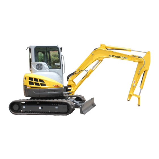
2. SPECIFICATIONS COMPONENTS NAME ARM CYLINDER BOOM BUCKET BOOM CYLINDER CYLINDER CANOPY OPERATING LEVER DOZER OPERATING LEVER LIGHT HYDRAULIC TANK LINK BUCKET THROTTLE LEVER MONITOR PANEL (GAUGE CLUSTER) TRAVEL LEVER RADIATOR CONTROL VALVE SWING CYLINDER AIR CLEANER SAFETY RESERVOIR LOCK LEVER TANK MUFFLER DOZER CYLINDER... -
Page 21: Machine Dimensions
2. SPECIFICATIONS MACHINE DIMENSIONS (1) E50B (CANOPY) Unit: mm (ft-in) 1940 { 6’4.4" } 5230 { 17’1.9" } 2140 { 7’0.3" } 1570 { 5’1.8" } 980 { 3’2.6" } 1690 { 5’6.5" } 400 { 15.7" } 1970 { 6’5.6" } 1560 { 5’1.4"... -
Page 22: Specifications And Performance
2. SPECIFICATIONS SPECIFICATIONS AND PERFORMANCE SPEED AND GRADEABILITY Model E50B Applicable Machines PJ06- Shoe Type Rubber shoe Iron shoe (OPT) Slewing Speed {rpm} 8.8 {8.8} Low (1st) High (2nd) Low (1st) High (2nd) Travel Speed km/h (mph) Gradeability % (degree) - Page 23 2. SPECIFICATIONS WEIGHT Rubber shoe Iron shoe Machine Weight kg (lb) 4,630 (10,200) 4,730 (10,400) Upper slewing body kg (lb) 2,280 (5,030) <-- Travel system kg (lb) 1,720 (3,790) 1,820 (4,010) Attachment kg (lb) 535 (1,180) (Boom+STD Arm+STD Bucket) Oil & Water kg (lb) 95 (209) This figure is calculated with Japanese standard bucket.
-
Page 24: Machine & Components Weight (Dry)
2. SPECIFICATIONS MACHINE & COMPONENTS WEIGHT (DRY) Unit ; kg (lb) E50B MODEL RUBBER SHOE IRON SHOE CANOPY CANOPY COMPLETE MACHINE 4,630 (10,200) 4,770 (10,500) 4,730 (10,400) 4,870 (10,700) 2,280 (5,030) 2,420 (5,340) 2,280 (5,030) 2,420 (5,340) UPPER FRAME ASSEMBLY (ASSY OF FOLLOWINGS) <--... - Page 25 2. SPECIFICATIONS Unit ; kg (lb) E50B MODEL RUBBER SHOE IRON SHOE CANOPY CANOPY FLUIDS (ASSY OF FOLLOWINGS) 95 (210) <-- <-- <-- HYDRAULIC OIL 45 (99) <-- <-- <-- FUEL 44 (97) <-- <-- <-- COOLANT 6 (13) <-- <--...
-
Page 26: Transportation
If machine cannot be transported with arm cylinder fully extended, remove bucket or attachment and extend arm cylinder. (2) TRANSPORTATION DIMENSION AND WEIGHT OF ATTACHMENT 1. BOOM WITH ARM CYLINDER Model E50B L X H X W 2,910 X 1,040 X 310 mm(ft-in) (9'6.6") (3'4.9") (12.2") Weight w/Arm cyl. - Page 27 2. SPECIFICATIONS 2. ARM & BUCKET (Japanese standard bucket) Model E50B L X H X W 2,770 X 510 X 650 mm (ft-in) (9'1.1") (20.1") (25.6") Weight kg (lb) 295 (650) 3. ARM Model E50B L X H X W...
- Page 28 2. SPECIFICATIONS 5. DOZER w/o cylinder weight Model E50B L X H X W 1,190 X 320 X 1,960 mm (ft-in) (3'11") (12.6") (6'5.2") Weight kg (lb) 175 (386) 2-11...
-
Page 29: Type Of Crawler Shoes
Total Crawler Shoe width Number of kPa (psi) Type Model width mm (in) Link mm (ft•in) CANOPY Rubber shoe E50B 400 (15.7") 1,970 (6'5") 26 (3.77) 27 (3.92) Iron shoe (option) E50B 400 (15.7") 1,970 (6'5") 26 (3.77) 27 (3.92) 2-12... -
Page 30: Type Of Bucket
Outer width mm (in) Number of Weight Type Model capacity Remarks with side without tooth kg (lb) (cu.yd) cutter side cutter Back hoe bucket Standard E50B 0.16 (0.21) 112 (247) (25.3") (23.6") size This table shows Japanese standard bucket. 2-13... -
Page 31: Engine Specifications
2. SPECIFICATIONS ENGINE SPECIFICATIONS 2.8.1 SPECIFICATIONS Model E50B Engine Model (YANMAR) 4TNV88-BXYB (EDM-4TNV88) Type Vertical, 4-cycle water-cooled diesel engine No. of cylinders - Bore × Stroke 4 - 88 mm (3.46 in) × 90 mm (3.54 in) Total displacement 2.189 liter (134 cu•in) Compression ratio 19.1... -
Page 32: Engine Performance Curve
2. SPECIFICATIONS 2.8.2 ENGINE PERFORMANCE CURVE E50B Model : 4TNV88-BXYB Rated Output : 29.3 kW / 2400 min (40 PS / 2,400 rpm) [Sd] [GT] (148) (129) [ T ] (111) (68) (92) (61) (74) [PS] (54) (55) (48) (37) - Page 33 2. SPECIFICATIONS 2-16...
- Page 34 3. ATTACHMENT DIMENSIONS 3. ATTACHMENT DIMENSIONS TABLE OF CONTENTS BOOM ........................3-3 3.1.1 BOOM DIMENSIONAL DRAWINGS ............3-3 3.1.2 BOOM MAINTENANCE STANDARDS ............3-4 ARM ........................3-8 3.2.1 ARM DIMENSIONAL DRAWINGS .............. 3-8 3.2.2 ARM MAINTENANCE STANDARDS ............3-10 BUCKET ......................3-14 3.3.1 BUCKET DIMENSIONAL DRAWINGS ............
- Page 35 3. ATTACHMENT DIMENSIONS Issue Date of Issue Applicable Machines Remarks S5PJ0333E01 First Edition April, 2010 E50B : PJ06- (NH-NA)
-
Page 36: Boom
3. ATTACHMENT DIMENSIONS BOOM 3.1.1 BOOM DIMENSIONAL DRAWINGS Boom Dimensional Drawings DIMENSIONS [mm(ft-in)] NAME E50B Boom length 2790 (9'1.84") Distance between pins of boss R1434 (4'8.46") Distance between pins of bracket R1487.5 (4'10.6") Height of boom cylinder rod pin 457.5 (18.0") Height of arm cylinder (head side) pin 908 (35.7") -
Page 37: Boom Maintenance Standards
3. ATTACHMENT DIMENSIONS 3.1.2 BOOM MAINTENANCE STANDARDS (1) Clearance of pin and bushing on boom section Clearance of pin and bushing on boom section Unit : mm (in) Standard dimensions Clearance Tolerance Standard Pos. Item Pin part No. Remedy Tolerance Standard Serviceabi Pin dia. - Page 38 3. ATTACHMENT DIMENSIONS This page is blank for editing convenience.
- Page 39 3. ATTACHMENT DIMENSIONS (2) Clearance in thrust direction on boom and cylinder installation section SECTION AA SECTION CC SECTION DD SECTION BB Clearance in thrust direction on boom section...
-
Page 40: Arm
3. ATTACHMENT DIMENSIONS Unit : mm (in) Standard Clearance X adjusted with shim Pin length dimensions (total of both sides) Sec. Item Remedy Standard Standard Serviceabili No. Dimensions value for No. Dimensions value ty limit repair Boom 0.008 0.1~0.5 (9.84 0.012 (0.004~ A-A Boom foot... - Page 41 This as a preview PDF file from best-manuals.com Download full PDF manual at best-manuals.com...
Need help?
Do you have a question about the E50B and is the answer not in the manual?
Questions and answers