Table of Contents
Advertisement
Advertisement
Chapters
Table of Contents

Related Manuals for New Holland E215B


Summary of Contents for New Holland E215B
- Page 1 HYDRAULIC EXCAVATOR SHOP E215B E215B MANUAL model (HS Engine) INDEX SPECIFICATIONS SECTION MAINTENANCE SECTION SYSTEM SECTION DISASSEMBLY SECTION TROUBLESHOOTING ENGINE SECTION PROCEDURE OF INSTALLING OPTIONS SECTION 87731204 Book Code No.
- Page 2 GENERAL SAFETY INFORMATION 3) CAUTION- Indicates a potentially hazardous situation which, if not avoided, may result in mi- nor or moderate injury. It may also be used to alert against possible damage to the machine Do not operate or perform any maintenance on this and its components and is represented as fol- machine until all instructions found in the OPERA- lows:...
- Page 3 SAFETY PRECAUTIONS stands, capable of supporting the machine, before performing any disassembly. The proper and safe lubrication and maintenance Do not operate this machine unless you have for this machine, recommended by Manufacturer, read and understand the instructions in the OP- are outlined in the OPERATOR’S MANUAL for the ERATOR’S MANUAL.
- Page 4 (13)Always use the proper tools that are in good condi- (21)Do not operate a machine if any rotating part is tion and that are suited for the job at hand. Be sure damaged or contacts any other part during opera- you understand how to use them before performing tion.
- Page 5 E215B NDEX NHK Middle East (HS Engine) E215BLC Book Code No. Index Title Distribution Year–Month S5YN0118E01 OUTLINE 2007-7 S5YN0225E01 SPECIFICATIONS 2007-7 S5YN0322E01 ATTACHMENT DIMENSIONS 2007-7 S5YN1122E01 TOOLS 2007-7 S5YN1221E01 STANDARD MAINTENANCE 2007-7 TIME SCHEDULE S5YN1318E02 MAINTENANCE STANDARD 2007-7 AND TEST PROCEDURE...
- Page 6 NOTE: This Manual is prepared as a technical material in This Manual may be properly revised due to the im- which the information necessary for the maintenance provement of products, modification of specifications, and repairing services of our hydraulic excavators are etc.
-
Page 7: Table Of Contents
1. OUTLINE TABLE OF CONTENTS GENERAL PRECAUTIONS FOR MAKING REPAIRS ............1-3 1.1.1 PREPARATION BEFORE DISASSEMBLING ............1-3 1.1.2 SAFETY WHEN DISASSEMBLING AND ASSEMBLING ........1-3 1.1.3 DISASSEMBLING AND ASSEMBLING HYDRAULIC EQUIPMENT .......1-3 1.1.4 ELECTRICAL EQUIPMENT ..................1-4 1.1.5 HYDRAULIC PARTS ....................1-5 1.1.6 WELD REPAIR ......................1-5 1.1.7 ENVIRONMENTAL ISSUES..................1-5 INTERNATIONAL UNIT SYSTEM ..................1-6... - Page 8 E235BSR : YF05-02001~ ↑ February, 2007 E235BSR(N)LC : YU05-02001~ (NHK) ↑ ↑ ↑ SK235SRLC-2 : YU05-02001~ (North America) ↑ E215B : YN11-45001~ ↑ March, 2007 E215BLC : YQ11-06001~ (NHK Russia) ↑ SK235SR-2 : YF05-02001~ ↑ April, 2007 SK235SRLC-2 : YU05-02001~ (OCE) ↑...
-
Page 9: General Precautions For Making Repairs
1. OUTLINE GENERAL PRECAUTIONS FOR 2) Attach "Don’t operate" tag to control lever, and begin a meeting before starting the work. MAKING REPAIRS 3) Before starting inspection and maintenance 1.1.1 PREPARATION BEFORE stop the engine. DISASSEMBLING 4) Confirm the position of first-aid kit and fire extinguisher, and also where to make contact for emergency measure and ambulance to Read Operator's Manual... -
Page 10: Electrical Equipment
1. OUTLINE 5) For parts which are required to use jig and tools, don’t fail to use the specified jig and tools. 6) For parts which can not be removed in the If hydraulic oil and lubricating oil are not specified procedure, never force removal. -
Page 11: Hydraulic Parts
1. OUTLINE (6) Engine key off before touching terminals of starter (2) Flexible hose (F hose) and alternator. • Even if the connector and length of hose are the (7) Remove battery grounding terminal before same, the parts differ according to the beginning work close to battery and battery relay withstanding pressure. -
Page 12: International Unit System
1. OUTLINE INTERNATIONAL UNIT SYSTEM (4) Derived Units bearing Peculiar Designations Table1-4 Introduction Although this manual uses the SI units system. Outline QUANTITY UNIT SYMBOL FORMULA of SI units system is described here. Frequency hertz 1Hz=1/s Given hereinunder are an excerpt of the units that are Force newton kg •... - Page 13 1. OUTLINE (6) Unit Conversion Table QUANTITIES REMARKS Mass Force 1kgf=9.807N Torque kgf•m N•m 1kgf•m=9.807N•m Pressure kgf/cm 1kgf/cm =0.098MPa Motive power 1PS=0.7355kW Revolution r.p.m 1r.p.m=1min –1 –1...
- Page 14 1. OUTLINE [MEMO]...
- Page 15 2. SPECIFICATIONS TABLE OF CONTENTS NAME OF COMPONENTS....................2-3 GENERAL DIMENSIONS ....................2-4 2.2.1 E215B/E215BLC ..2-4 [5.65m (18ft-6in) Boom+2.94m (9ft-8in) Standard Arm+0.80m (1.05cu•yd) Bucket Shoe] 2.2.2 E215B/E215BLC [5.65m (18ft-6in)+2.4m (7ft-10in) Short Arm+0.93m (1.22cu•yd) Bucket Shoe] ..2-4 2.2.3 E215B/E215BLC ..2-5 [5.65m (18ft-6in) Boom+3.5m (11ft-6in) Long Arm+0.70m (0.92cu•yd) Bucket Shoe]...
- Page 16 2. SPECIFICATIONS Issue Date of Issue Applicable Machines Remarks E215B : YN11-45001~ S5YN0225E01 First edition July, 2007 E215BLC : YQ11-06001~ (NHK Russia) HS Engine ↑ ↑ ↑ ↑ (NHK Middle East) HS Engine...
-
Page 17: Name Of Components
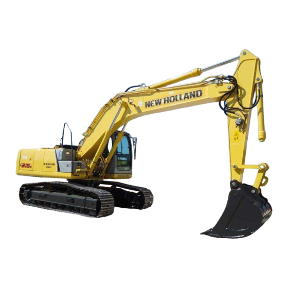
2. SPECIFICATIONS NAME OF COMPONENTS ARM CYLINDER BOOM BOOM CYLINDER BUCKET CYLINDER SLEWING BEARING IDLER LINK SLEWING MOTOR SWIVEL JOINT FUEL TANK HYDRAULIC TANK BUCKET LINK CONTROL VALVE GUARD MUFFLER HYDRAULIC PUMP BUCKET MONITOR PANEL SHOE AND TRACK LINK FRONT IDLER ENGINE IDLER ADJUST COUNTER WEIGHT... -
Page 18: General Dimensions
2. SPECIFICATIONS GENERAL DIMENSIONS 2.2.1 E215B/E215BLC [5.65m (18ft-6in) Boom+2.94m (9ft-8in) Standard Arm+0.80m (1.05cu•yd) Bucket Shoe] Unit : mm(ft-in) 9450 (31') 2750 (9') 600 (23.6") 4170 (13'8") [4450 (14'7")] 2800 (9'2") 4840 (15'11") [4980 (16'4")] [2990] (9'10") Dimensions marked * do not include the height of the shoe lug. -
Page 19: E215B/E215Blc
2. SPECIFICATIONS 2.2.3 E215B/E215BLC [5.65m (18ft-6in) Boom+3.5m (11ft-6in) Long Arm+0.70m (0.92cu•yd) Bucket Shoe] Unit : mm(ft-in) 9520 (31'3") 2750 (9') 4170 (13'8") [4450 (14'7")] 4840 (15'11") [4980 (16'4")] Dimensions marked * do not include the height of the shoe lug. -
Page 20: Weight Of Components
2. SPECIFICATIONS WEIGHT OF COMPONENTS Unit ; kg (lb) Model E215B E215BLC Item Machine complete 20,200 (44,500) 20,600 (45,400) ← 1. Upper frame assy (Assembly of following :) 9,500 (21,000) ← 1.1 Upper frame 1,770 (3,900) ← 1.2 Counter weight (Semi-weighted) 4,640 (10,230) ←... - Page 21 2. SPECIFICATIONS Unit ; kg (lb) Model E215B E215BLC Item ← 4. Lubricant and water (Assembly of following :) 550 (1,210) ← 4.1 Hydraulic oil 200 (440) ← 4.2 Engine oil 20 (44) ← 4.3 Fuel 310 (680) ← 4.4 Water 20 (44) Marks * show dry weight.
- Page 22 Thanks very much for your reading, Want to get more information, Please click here, Then get the complete manual NOTE: If there is no response to click on the link above, please download the PDF document first, and then click on it. Have any questions please write to me: admin@servicemanualperfect.com...
Need help?
Do you have a question about the E215B and is the answer not in the manual?
Questions and answers
Вибрация в распределителе при длительной работе и нагрев масла экскаватор кобелко 215