
Related Manuals for New Holland E55Bx Tier 3


Summary of Contents for New Holland E55Bx Tier 3
- Page 1 SERVICE MANUAL E55Bx Tier 3 Compact Hydraulic Excavator Part number S5HS0014E01 English April 2014 Copyright © 2014 CNH Industrial America LLC. All Rights Reserved.
- Page 2 HYDRAULIC EXCAVATOR SHOP E55Bx MANUAL model INDEX SPECIFICATIONS SECTION MAINTENANCE SECTION SYSTEM SECTION DISASSEMBLY SECTION TROUBLESHOOTING ENGINE SECTION S5HS0014E01 Book Code No. Find manuals at https://best-manuals.com...
- Page 3 3) CAUTION- Indicates a potentially hazardous GENERAL SAFETY INFORMATION situation which, if not avoided, may result in mi- nor or moderate injury. It may also be used to alert against possible damage to the machine and its components and is represented as fol- Do not operate or perform any maintenance on this lows: machine until all instructions found in the OPERA-...
- Page 4 stands, capable of supporting the machine, before SAFETY PRECAUTIONS performing any disassembly. The proper and safe lubrication and maintenance Do not operate this machine unless you have for this machine, recommended by Manufacturer, read and understand the instructions in the OP- are outlined in the OPERATOR’S MANUAL for the ERATOR’S MANUAL.
- Page 5 (13)Always use the proper tools that are in good condi- (21)Do not operate a machine if any rotating part is tion and that are suited for the job at hand. Be sure damaged or contacts any other part during opera- you understand how to use them before performing tion.
- Page 6 INDEX E55Bx Book Code No. Index 25 1 Title Distribution Year–Month S5PA0105E01 OUTLINE 2013-12 S5PS0214E01 SPECIFICATIONS 2013-12 S5PS0314E01 ATTACHMENT DIMENSIONS 2013-12 S5PS1113E01 TOOLS 2013-12 STANDARD MAINTENANCE S5PS1214E01 TIME SCHEDULE 2013-12 MAINTENANCE STANDARD S5PS1314E01 AND TEST PROCEDURE 2013-12 43 11 MECHATRO CONTROL S5PS2114E01 (OPT.) 2013-12...
- Page 7 NOTE: This Manual is prepared as a technical material in This Manual may be properly revised due to the im- which the information necessary for the maintenance provement of products, modification of specifications, and repairing services of our hydraulic excavators are etc.
-
Page 8: Table Of Contents
1. OUTLINE 1. OUTLINE TABLE OF CONTENTS GENERAL PRECAUTIONS FOR REPAIRS ............1-3 1.1.1 PREPARATION BEFORE DISASSEMBLING ..........1-3 1.1.2 SAFETY IN DISASSEMBLING AND ASSEMBLING ........1-3 1.1.3 DISASSEMBLING AND ASSEMBLING HYDRAULIC EQUIPMENT ..1-4 1.1.4 ELECTRICAL EQUIPMENT ................1-6 1.1.5 HYDRAULIC PARTS ..................1-7 1.1.6 WELDING REPAIR ..................1-7 1.1.7 ENVIRONMENTAL MEASURE ..............1-7... - Page 9 Find manuals at https://best-manuals.com...
-
Page 10: General Precautions For Repairs
1. OUTLINE GENERAL PRECAUTIONS FOR REPAIRS 1.1.1 PREPARATION BEFORE DISASSEMBLING Read Operator's Manual before disassembling (1) Understanding operating procedure Read OPERATOR'S MANUAL carefully to understand the operating procedure. (2) Cleaning machines Remove soil, mud, and dust from the machine before carrying it into the service shop to prevent loss of work efficiency, damage of parts, and difficulty in rust prevention and dust protection while reassembling. -
Page 11: Disassembling And Assembling Hydraulic Equipment
1. OUTLINE 1.1.3 DISASSEMBLING AND ASSEMBLING HYDRAULIC EQUIPMENT (1) Removing hydraulic equipment 1. Before disconnecting pipes, release the hydraulic pressure of the system, or open the return side cover and take out the filter. 2. Carefully drain oil of the removed pipes into a containers without spilling on the floor. 3. - Page 12 1. OUTLINE (5) Installing hydraulic equipment 1. Ensure hydraulic oil and lubricant are properly supplied. 2. Perform air bleeding when : a. Hydraulic oil changed b. Parts of suction side piping replaced c. Hydraulic pump installed d. Slewing motor installed e.
-
Page 13: Electrical Equipment
1. OUTLINE 1.1.4 ELECTRICAL EQUIPMENT (1) Do not disassemble electrical equipment. (2) Handle it carefully not to drop and give a shock. (3) Turn the key OFF prior to connecting and disconnecting work. (4) Disconnect the connector by holding it and pressing the lock. Do not pull the wire to apply force to the caulking portion. -
Page 14: Hydraulic Parts
1. OUTLINE 1.1.5 HYDRAULIC PARTS (1) O-ring • Ensure O-rings have elasticity and are not damaged before use. • Use the appropriate O-rings. O-rings are made of various kinds of materials having different hardness to apply to a variety of parts, such as the part for moving or fixed portion, subjected to high pressure, and exposed to corrosive fluid, even if the size is same. -
Page 15: International Unit Conversion System (Based On Marks' Standard Handbook For Mechanical Engineers)
1. OUTLINE INTERNATIONAL UNIT CONVERSION SYSTEM (Based on MARKS' STANDARD HANDBOOK FOR MECHANICAL ENGINEERS) Introduction Base units Table 1-1 Although this manual includes International System of Unit Derived units and Foot-Pound System of Units, if you need SI unit, refer of base units Supplemen to the following international system of units. - Page 16 1. OUTLINE (5) Prefixes of SI (6) Unit Conversion Table 1-5 Table 1-6 PREFIX SYMBOL MULTIPLICATION FACTORS QUANTITY Gravitational CONVERSION FACTOR giga Mass mega Force 1 kgf=9.807 N kilo Torque kgf•m N•m kgf•m=9.807 N•m hecto Pressure kgf/cm MPa 1 kgf/cm =0.09807 MPa deca Motive...
- Page 17 1. OUTLINE 1-10...
- Page 18 2. SPECIFICATIONS 2. SPECIFICATIONS TABLE OF CONTENTS COMPONENTS NAME ..................2-3 MACHINE DIMENSIONS ..................2-4 SPECIFICATIONS AND PERFORMANCE ............2-5 MACHINE & COMPONENTS MASS (DRY) ............2-7 TRANSPORTATION .....................2-9 TYPE OF CRAWLER SHOES ................2-12 TYPE OF BUCKET ....................2-13 ENGINE SPECIFICATIONS .................2-14 2.8.1 SPECIFICATIONS ..................2-14 2.8.2 ENGINE PERFORMANCE CURVE .............2-15 Book Code No.
-
Page 20: Components Name
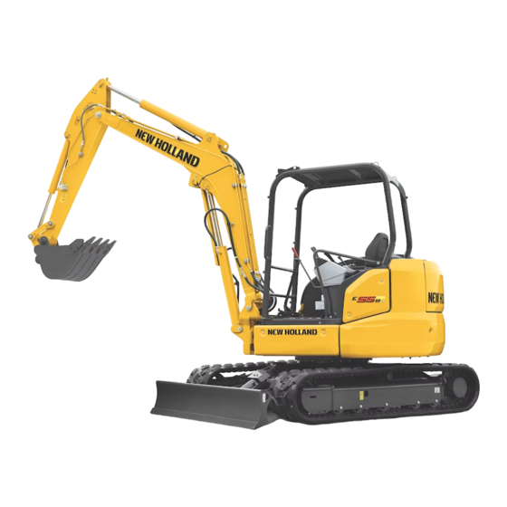
2. SPECIFICATIONS COMPONENTS NAME ARM CYLINDER BOOM BOOM SWING CYLINDER BUCKET CYLINDER CANOPY SLEWING MOTOR BATTERY LIGHT IDLER LINK FUEL TANK BUCKET LINK GUARD BUCKET HYDRAULIC TANK BOOM CYLINDER RADIATOR DOZER CYLINDER RESERVOIR DOZER TANK AIR CLEANER COUNTER WEIGHT RUBBER CRAWLER SHOE IDLER ASSY CONTROL VALVE ENGINE... -
Page 21: Machine Dimensions
2. SPECIFICATIONS MACHINE DIMENSIONS (1) E55Bx (CANOPY) Unit ; mm {ft-in} 1940 {6’4”} 5550 {18’3”} 2360 {7’9”} 1770 {5’10”} 1170 {3’10”} 1700 {5’7”} 2000 {6’7”} {15.7”} 1560 {5’1”} 2500 {8’2”} 1960 {6’5”} 2920 {6’7”} (2) E55Bx (CAB) Unit ; mm {ft-in} 1940 {6’4”} 5550 {18’3”} 2360 {7’9”}... -
Page 22: Specifications And Performance
2. SPECIFICATIONS SPECIFICATIONS AND PERFORMANCE SPEED AND GRADEABILITY E55Bx c i l Swing Speed Low (1st) High (2nd) Low (1st) High (2nd) Travel Speed km/h (mph) 2.1 (1.3) 4.0 (2.5) 2.1 (1.3) 3.7 (2.3) l i b y t i ENGINE n i l direct injection type diesel engine... - Page 23 2. SPECIFICATIONS MASS Rubber shoe Iron shoe Machine Mass kg (lb) 4,900 (10,810) 5,040 (11,110) Upper swing body kg (lb) 2,290 (5,050) <-- Travel system kg (lb) 1,750 (3,860) 1,900 (4,190) Attachment kg (lb) 640 (1,410) (Boom+STD Arm+STD Bucket) Oil & Water kg (lb) 120 (265) This figure is calculated with Japanese standard bucket.
-
Page 24: Machine & Components Mass (Dry)
2. SPECIFICATIONS MACHINE & COMPONENTS MASS (DRY) Unit ; kg (lb) E55Bx MODEL RUBBER SHOE IRON SHOE CANOPY CANOPY COMPLETE MACHINE 4,900 (10,810) 5,020 (11,070) 5,040 (11,110) 5,160 (11,380) UPPER FRAME ASSEMBLY 2,290 (5,050) 2,410 (5,310) 2,290 (5,050) 2,410 (5,310) (ASSY OF FOLLOWINGS) UPPER FRAME 570 (1,257) - Page 25 2. SPECIFICATIONS Unit ; kg (lb) E55Bx MODEL RUBBER SHOE IRON SHOE CANOPY CANOPY FLUIDS (ASSY OF FOLLOWINGS) 120 (265) <-- <-- <-- HYDRAULIC OIL 51 (112) <-- <-- <-- FUEL 63 (139) <-- <-- <-- COOLANT 6 (13) <-- <-- <-- Mark * shows dry mass.
-
Page 26: Transportation
2. SPECIFICATIONS TRANSPORTATION (1) LOADING MACHINE ON A TRAILER 1. Keep trailer bed clean. Put chocks against truck wheels. 2. Use a ramp or loading deck. Ramps must be strong enough, have a low angle, and correct height. Load and unload machine on a level surface. - Page 27 2. SPECIFICATIONS 2. ARM & BUCKET (Japanese standard bucket) 1.69m(5ft-6.5in)Arm + 1.69m(5ft-6.5in)Arm + Item / Type 0.16m3(0.21cu.yd) STD Bucket 0.21m3(0.28cu.yd)Bucket L X H X W 2,900 X 530 x 650 2,900 X 550 X 750 mm (ft-in) (9'6.2") (20.9") (25.6") (9'6.2") (21.7") (29.5") Mass kg (lb) 284 (626)
- Page 28 2. SPECIFICATIONS 5. DOZER w/o cylinder mass L X H X W 1,250 X 330 X 1,960 mm (ft-in) (4'1.2") (13") (6'5.2") Mass kg (lb) 219 (483) 2-11...
-
Page 29: Type Of Crawler Shoes
2. SPECIFICATIONS TYPE OF CRAWLER SHOES Length between Ground Pressure center of idler and kPa {psi} Width Type center of travel mm {in} motor CANOPY mm {ft-in} Rubber belt 28.0 28.7 {15.7"} {4.1} {4.2} 1,960 {6'5"} Iron shoe (Optional) 29.7 30.4 {15.7"} {4.2}... -
Page 30: Type Of Bucket
2. SPECIFICATIONS TYPE OF BUCKET Outer width mm (in) Heaped Number of Mass Type capacity Remarks with side without tooth kg (lb) (cu.yd) cutter side cutter Back hoe bucket Standard 0.16 (0.21) 106 (234) (25.3") (23.6") size This table shows Japanese standard bucket. 2-13... -
Page 31: Engine Specifications
2. SPECIFICATIONS ENGINE SPECIFICATIONS 2.8.1 SPECIFICATIONS E55Bx Engine Model (YANMAR) 4TNV88-B Type Vertical, 4-cycle water-cooled diesel engine, DI, NA No. of cylinders - Bore 90 mm (3.54 in) l a t t i l i • • • f ) t f n i l ±... -
Page 32: Engine Performance Curve
2. SPECIFICATIONS 2.8.2 ENGINE PERFORMANCE CURVE E55Bx Model : 4TNV88-B Rated Output : 28.3 kW / 2400 min (38.5 PS / 2,400 rpm) Smoke Exhaust Gas Temp. (lbf . ft) N . m (20) 200 (18) 175 (15) 150 (ps) Torque (13) 125 (68) - Page 33 2. SPECIFICATIONS 2-16...
- Page 34 3. ATTACHMENT DIMENSIONS 3. ATTACHMENT DIMENSIONS TABLE OF CONTENTS BOOM ........................3-3 3.1.1 BOOM DIMENSIONAL DRAWINGS ............3-3 3.1.2 BOOM MAINTENANCE STANDARDS ............3-4 ARM ........................3-8 3.2.1 ARM DIMENSIONAL DRAWINGS .............. 3-8 3.2.2 ARM MAINTENANCE STANDARDS ............3-10 BUCKET ......................3-13 3.3.1 BUCKET DIMENSIONAL DRAWINGS ............
-
Page 36: Boom
3. ATTACHMENT DIMENSIONS BOOM 3.1.1 BOOM DIMENSIONAL DRAWINGS Boom Dimensional Drawings NAME DIMENSIONS [mm(ft-in)] Boom length 2985 (9'9.52") Distance between pins of boss R1432 (4'8.38") Distance between pins of bracket R1475 (4'10.1") Height of boom cylinder rod pin 440 (17.3") Height of arm cylinder (head side) pin 830 (32.7") Boom foot width... -
Page 37: Boom Maintenance Standards
3. ATTACHMENT DIMENSIONS 3.1.2 BOOM MAINTENANCE STANDARDS (1) Clearance of pin and bushing on boom section Clearance of pin and bushing on boom section Unit : mm (in) Standard dimensions Clearance Tolerance Standard Pos. Item Pin part No. Remedy Tolerance Standard Serviceabi Pin dia. - Page 38 3. ATTACHMENT DIMENSIONS This page is blank for editing convenience.
- Page 39 3. ATTACHMENT DIMENSIONS (2) Clearance in thrust direction on boom and cylinder installation section SECTION AA SECTION CC SECTION DD SECTION BB Clearance in thrust direction on boom section...
- Page 40 3. ATTACHMENT DIMENSIONS Unit : mm (in) Standard Clearance X adjusted with shim Pin length dimensions (total of both sides) Sec. Item Remedy Standard Standard Serviceabili No. Dimensions value for No. Dimensions value ty limit repair Boom 0.008 0.1~0.5 (9.84 0.016 A-A Boom foot (0.004~...
-
Page 41: Arm
3. ATTACHMENT DIMENSIONS 3.2.1 ARM DIMENSIONAL DRAWINGS SECTION Z-Z SECTION X-X SECTION Y-Y Arm dimensional drawings... - Page 42 3. ATTACHMENT DIMENSIONS Name Dimensions [mm(ft-in)] Arm length 1685 (5'6.34") Distance between pins of boss and bracket R405 (15.9") Distance between pins of boss and bracket R1118 (3'8.02") Distance between pins of boss and boss R230.5 (9.07") Height between pins of boss and bracket 326 (12.8") Height between pins of boss and bracket 204 (8.03")
-
Page 43: Arm Maintenance Standards
3. ATTACHMENT DIMENSIONS 3.2.2 ARM MAINTENANCE STANDARDS (1) Clearance of pin and bushing D, D’ Clearance of pin and bushing on arm section Unit : mm (in) Standard dimensions Clearance Tolerance Standard Pos. Item Pin part No. Remedy Tolerance Standard Serviceabili Pin dia. - Page 44 3. ATTACHMENT DIMENSIONS (2) Clearance in thrust direction on arm and cylinder installation section SECTION CC SECTION AA SECTION BB This clearance is adjusted with shim 0.1~0.5mm (0.004"~0.020") L4 X SECTION DD SECTION EE SECTION FF SECTION GG Clearance in thrust direction on arm section 3-11...
- Page 45 3. ATTACHMENT DIMENSIONS Unit : mm (in) Standard Clearance X adjusted with Pin length dimensions shim (total of both sides) Sec. Item Remedy Standard Servicea Standard Dimensions value for bility No. Dimensions value repair limit (5.91 0.024 287.5 Arm point (11.3) Bucket 0.035...
-
Page 46: Bucket
3. ATTACHMENT DIMENSIONS BUCKET 3.3.1 BUCKET DIMENSIONAL DRAWINGS Bucket dimensional drawings Heaped Capacity m 0.16 (cu-yd) (0.20) Distance between pin and bracket 228.5 (9") Distance between bucket pin and tooth end R800 (31.5") Inner width of bucket top end 571 (22.5") Inner width of lug 151 (5.95") Inner width of bracket... -
Page 47: Detail Dimensional Drawings Of Lug Section
3. ATTACHMENT DIMENSIONS 3.3.2 DETAIL DIMENSIONAL DRAWINGS OF LUG SECTION Dimension of lug section Unit : mm (in) Plate outer dia. Boss thickness Pin bore dia. Lug plate thickness Portion øA øC ø95 ø45 Dimensions (3.74) (0.906) (0.551) (1.77 3.3.3 DETAIL DIMENSIONAL DRAWINGS OF BOSS SECTION Dimension of boss section Unit : mm (in) - Page 48 3. ATTACHMENT DIMENSIONS This page is blank for editing convenience. 3-15...
-
Page 49: Dozer
3. ATTACHMENT DIMENSIONS DOZER 3.4.1 DOZER DIMENSIONAL DRAWINGS Dozer dimensional drawings NAME Dimensions [mm(ft-in)] Blade width 1960 (6'5.17") Blade height 346 (13.6") Distance from dozer attaching pin center to cutting edge end R1251 (4'1.25") Inner width of dozer attaching bracket 531 (20.9") Width of dozer attaching bracket 69 (2.72") -
Page 50: Dozer Maintenance Standards
3. ATTACHMENT DIMENSIONS 3.4.2 DOZER MAINTENANCE STANDARDS PIN A PIN B PIN C Dozer maintenance standards (1) Clearance of pin and bushing Unit : mm (in) Standard dimension Clearance Tolerance Tolerance Standard Pos. Item Pin part No. Remedy Standard Serviceabi Pin dia. - Page 51 This as a preview PDF file from best-manuals.com Download full PDF manual at best-manuals.com...
Need help?
Do you have a question about the E55Bx Tier 3 and is the answer not in the manual?
Questions and answers