ecobee SMART - Smart Thermostat Manual
- Installation manual (20 pages) ,
- User manual (18 pages)
Advertisement
- 1 GETTING STARTED
- 2 INSTAllING THE SMART THERMOSTAT
- 3 NAVIGATING THE SMART THERMOSTAT
-
4
CONFIGuRING THE SMART THERMOSTAT
- 4.1 Configuring the Installer Settings
- 4.2 Installation Wizard
- 4.3 Equipment
- 4.4 Thresholds
- 4.5 Test Equipment
- 4.6 Sensors
- 4.7 Setting Up the Remote Sensor Inputs
- 4.8 View Wiring Diagram
- 4.9 Contractor Info
- 4.10 Reset Installation Settings
- 4.11 Reset All Setting
- 4.12 Performing a Hardware reset
- 4.13 Configuring reminder alerts
- 4.14 List of Alerts
- 5 Documents / Resources
GETTING STARTED
Welcome
The ecobee Smart Thermostat has been designed in partnership with HVAC contractors to ensure the installation process is simple and efficient. This step-by-step Installation Manual will walk you through all aspects of the installation.
To ensure an on-going service relationship with your customers, please register all of your ecobee Smart Thermostats in your Contractor Portal.
-The ecobee Team-
Technical support
Our technical support team is available to answer your questions at 1.877-9-ecobee (1.877.932.6233), or via email at support@ecobee.com.
Before You Begin
This product is intended to be installed by trained service professionals
This manual explains the procedures for installing the ecobee Smart Thermostat. Please read it carefully before beginning the installation.
For information on how to operate the ecobee Smart Thermostat, please see the ecobee User's Manual.
The ecobee Smart Thermostat consists of two parts (see images below):

- A Smart Thermostat to be mounted on the homeowner's wall.
- An Equipment Interface Module This should be mounted in the homeowner's utility room and connects to the heating, cooling and ventilation equipment.
![]()
Disconnect electric power to the system before installing this product. Failure to do so could result in electric shock and/or equipment damage.
All wiring must conform to your local electrical code.
Mercury Notice: This product does not contain mercury. If you are replacing a product that does contain mercury please contact your local waste-management authority for disposal instructions. Do not discard the old product in the regular trash.

HVAC System Compatibility information
ecobee is designed to operate low-voltage heating and cooling systems. It is not designed for use with linevoltage or millivolt heating and cooling systems. ecobee supports control of up to four heating stages and two cooling stages. It also supports control of humidifiers, dehumidifiers, heat-recovery ventilators and energy-recovery ventilators.
Equipment Description
| Gas/Oil/Electric heating (up to three stages) | Yes |
| Heat pump with auxiliary heat (up to four stages) | Yes |
| Geothermal Heat Pump | Yes |
| Duel fuel systems | Yes |
| Standard electric cooling (up to two stages) | Yes |
| Boilers | Yes |
| Central humidifier | Yes |
| Central dehumidifier | Yes |
| Heat Recovery Ventilator (HRV) | Yes |
| Energy Recovery Ventilator (ERV) | Yes |
| Sensors with dry contact outputs | Yes |
Specifications
Temperature ranges
Heat: 45 – 79°F (7 – 26°C)
Cool: 58 – 92°F (14 – 33°C)
Display: 40 – 100°F (5 – 37°C)
Sensitivity: +/- 1°F (0.5°C)
Equipment Interface Operating: -40o to 160oF (-40o to 70oC)
Thermostat Operating: 32o to 130oF (0o to 55oC)
Humidity Range
Humidify: 20 to 50% R.H
Dehumidify: 30 to 60% R.H Display: 0 - 90% R.H
Sensitivity: +/- 2% R.H.
Operating: 5 – 95% R.H non-condensing
Dimensions
Thermostat: 5.5"W x 3.25"H x 1"D (139.5mm H x 82.5mm W x 25mm D)
Equipment Interface: 4.6"W x 10"H x 1.3"D (118mm W x 254mm H x 32mm D)
Power
AC Transformer - 24 VAC - 3VA Minimum (not included)
Battery – CR2032 – 3V lithium coin cell (included),
Power Adaptor - #EB-PS-01 - 120V 50/60Hz to 12V DC 1A (not included)
Wiring Specifications
Refer to this table to determine maximum wire lengths allowed:
Smart Thermostat to Equipment Interface
| 18 AWG | 20 AWG | 22 AWG |
| 1250ft/380m | 790ft/240m | 500ft/150m |
Equipment Interface to heating/air equipment
| 18 AWG | 20 AWG | 22 AWG |
| 128ft/39m | 80ft/24m | 50ft/15m |
Terminal Description and Electrical Ratings
| Terminal | Description | Voltage | Current max |
| Y | 1st stage cooling | 30V AC | 3A |
| W (O/B) | 1st stage heating (or changeover) | 30V AC | 3A |
| G | Fan | 30V AC | 3A |
| W2(AUX) | 2nd stage heating (or 1st auxiliary heat) | 30V AC | 3A |
| R/H | Heat transformer return | 30V AC | 3A |
| R/C | Cool transformer return | 30V AC | 3A |
| ACC1 | 1st accessory relay | 30V AC | 3A |
| ACC1r | 1st accessory relay return | 30V AC | 3A |
| ACC2 | 2nd accessory relay | 30V AC | 3A |
| ACC2r | 2nd accessory relay return | 30V AC | 3A |
| ACC3 | 3rd accessory relay | 30V AC | 3A |
| ACC3r | 3rd accessory relay return | 30V AC | 3A |
| IN1 + | Input 1 + | Dry contact only | Dry contact only |
| IN1- | Input 1 - | Dry contact only | Dry contact only |
| IN2+ | Input 2 + | Dry contact only | Dry contact only |
| IN2- | Input 2- | Dry contact only | Dry contact only |
| +12v | 12V DC power to Thermostat | 8-14V DC | 600mA |
| GND | GND to Thermostat | - | - |
| D+ | Data + communication line | - | - |
| D- | Data – communication line | - | - |
INSTAllING THE SMART THERMOSTAT
There are five steps to installing the ecobee Smart Thermostat
- Install the Equipment Interface.
- Wire the Equipment Interface.
- Install the Smart Thermostat.
- Connect the Smart Thermostat to the Equipment Interface.
- Power up both devices.
Installing the Equipment Interface
To install the Equipment Interface:
- In the homeowner's utility room or basement, select a suitable location either on a wall or on the cold air return plenum. Make sure the surface is relatively flat and, if you are using a power adaptor, make sure there is an electrical outlet within five feet of where you plan to mount the device.
- Remove the front cover of the Equipment Interface. If necessary, Insert a flat-head screwdriver into one of the slots as shown below, and gently twist the screwdriver.
Insert a screwdriver into one of the two slots and twist gently
![]()
- Place the back of the enclosure on the intended mounting surface and use it as a template to mark the location of the mounting holes, as shown below.
Mounting holes indicated with solid color
![]()
- Move the back of the enclosure out of the way and make the holes where indicated in step 3. The mounting holes can accommodate a #6 pan-head screw.
- Use drywall plugs or other screw anchors (not included) to ensure the Equipment Interface can be mounted securely.
- Fasten the backplate to the wall using the appropriate screws (not included).


Wiring the Equipment Interface
To wire the Equipment Interface:
- Disconnect the power to the heating and air conditioning equipment.
- Disconnect the wires going to the existing Thermostat.
- Using the wiring diagrams, connect the heating or air conditioning equipment to the Equipment Interface.
- Do not apply power until you have installed and connected the Smart Thermostat. (see instructions)
- Do not install the front cover on the Equipment Interface at this point.
Wiring Diagrams
Below are the Equipment Interface Terminal Labels
Please take note that there is a factory installed jumper between R/H and R/C.

Single Stage Heat/Cool with Thrre Accessories

Dual Stage Heat, Single Stage Cool with Three Accessories

Dual Stage Heat/Cool with Two Accessories

Three Stage Heat, Two Stage Cool with One Accessory

Single Stage Heat/Cool, Dual Stage Auxiliary Heat with Humidifer

Dual Stage Heat/Cool, Single Stage Auxiliary Heat with Two Accessories

Dual Stage Heat/Cool, Dual Stage Auxiliary Heat with One Accessory

Dual Stage Furnace with Dehumidifier and Two Stage Heat Pump

Single Stage Cooling with Boiler

Dual Stage Cooling with Boiler


indicates a jumper. Non-powered accessories require a jumper from RH / RC to ACC1, ACC2, ACC3 for a 24V feed.
![]() Remove factory installed jumper
Remove factory installed jumper
Installing the Smart Thermostat
The ideal location for the Smart Thermostat is approximately five feet (1.5m) above floor level in the main living area.
Do not install the Smart Thermostat:
- Close to sources of heat such as incandescent lights or heating/cooling registers.
- In direct sunlight.
- On exterior, non-insulated or poorly insulated walls.
- In the kitchen or other areas of potentially high heat and/or humidity.
- In an area that could restrict air flow.
To Install the Smart Thermostat:
- Remove the front cover of the Smart Thermostat, insert a flat-head screwdriver into one of the slots as shown below and gently twist the screwdriver.
Insert screwdriver into one of the two slots and twist gently
![]()
- Place the Smart Thermostat backplate on the wall. Make sure that any existing wires can be inserted through the opening for the wiring.
- Using the backplate as a template, mark the location of the mounting holes on the wall as shown below.
The solid color indicates mounting holes
![]()
- Move the backplate out of the way and make holes where indicated in step 3. The mounting holes can accommodate a #6 pan-head screw.
- Use drywall plugs or other screw anchors (not included) to ensure the Smart Thermostat can be mounted securely to the wall.
- Fasten the backplate to the wall using the appropriate screws (not included).


Connecting the Smart Thermostat to the Equipment Interface
Only four wires are needed to connect the Smart Thermostat to the Equipment Interface. If you are replacing a Thermostat, you can use the existing wiring.
Note: Ensure any unused wires do not have exposed bare copper conductors.
Follow these steps to connect the Smart Thermostat to the Equipment Interface:
- Connect the wires between the Smart Thermostat and Equipment Interface as shown below.
Wiring from Smart Thermostat to the Equipment Interface
![]()
- Attach the front cover of the Smart Thermostat to the backplate. Ensure the four pins on the circuit board mate with the terminal block on the backplate as shown below.
Replace the front cover ensuring the pins meet the terminals

Slide the battery under the contacts and push down firmly


The Thermostat comes with a factory installed, coin cell battery. When replacing the battery ensure the + side of the battery is facing out and the battery contacts remain in the upright position (not bent underneath the battery).
The battery should snap in easily.
Connecting Power
Once you've completed the wiring of the Smart Thermostat and Equipment Interface, you can apply power to the Equipment Interface and restore power to the heating and air conditioning equipment.
There are two methods of powering the Smart Thermostat. You can power it directly from a 24VAC source capable of at least 3VA.
Hard-wired 24 VAC option

The second method requires the optional 120V to 12Vdc power adaptor. Plug the power supply into a standard electrical outlet and plug the barrel connector into the Equipment Interface.

Plug the adaptor into the Equipment Interface
Equipment Interface Status LED
The Equipment Interface has four LEDs to display the status of the system.
If you've wired the system correctly, only the Power LED should be on.
LED arrangement

The LEDs operate as follows:
| Power | This LED monitors the power supply of the Equipment Interface. |
| LED ON | Power is connected to the Equipment Interface and is within the appropriate voltage range. |
| LED OFF | Power is disconnected or has dropped below 9V. |
| System | This LED monitors the operation of the Equipment Interface. |
| LED ON | There is a fault with the Equipment Interface. |
| LED OFF | The equipment interface is operational. |
| Line | This LED monitors the power supplied to the Smart Thermostat from the Equipment Interface. |
| LED ON | The voltage at the +12V and GND terminal has dropped below 7V. |
| LED OFF | Adequate power is being supplied to the Smart Thermostat. |
| Communication | This LED monitors the communication between the Smart Thermostat and the Equipment Interface (i.e., the D+ and D- terminals). |
| LED ON | The Equipment Interface and Smart Thermostat are not communicating with each other. |
| LED OFF | The two devices are communicating properly. |
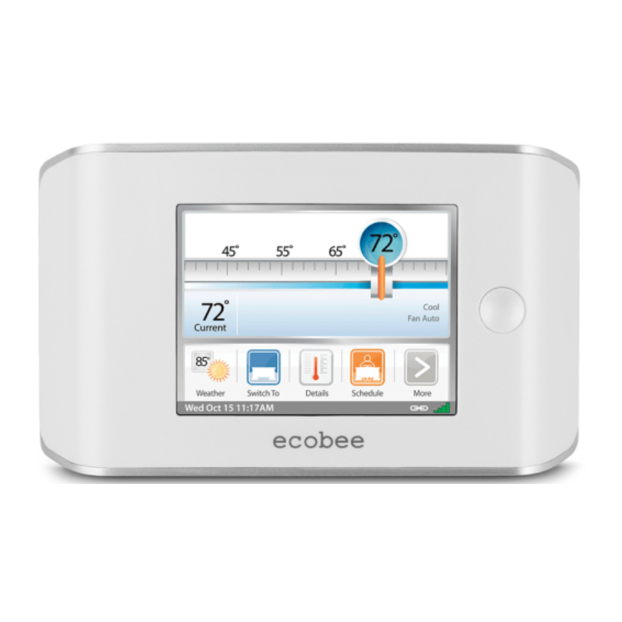
NAVIGATING THE SMART THERMOSTAT
Once the Smart Thermostat and Equipment Interface are powered up and working correctly, you can begin configuring the system.
The Smart Thermostat uses touch screen technology, so it's easy to navigate – just tap the icons, buttons and lists.
Note: To prevent damage to the touch screen, never use a sharp object such as a pen.
 When the screen shows a list setting an arrow on the right, it indicates there are more than two options to choose from.
![]() If there is no arrow, then the list item only has two options. Toggle between options by pressing the list item.
If there is no arrow, then the list item only has two options. Toggle between options by pressing the list item.
In the various screens, you have three navigation choices:
Press Done to save changes and move to the next screen.

Press Cancel to go back to the previous screen without saving changes.

At any time, press the Home button (found on the right-hand side of the touch screen). This cancels any action and takes you back to the home screen.
If you need to enter data in the form of text, you will be presented with a keyboard.
Pressing the Caps key will allow you to enter capital letters; pressing the 123@ key will change the letters to numbers or commonly used symbols.
CONFIGuRING THE SMART THERMOSTAT
Configuring the Installer Settings
Installer Settings let you configure the settings related to the various devices (such as a furnace, air conditioner, humidifier, dehumidifier or ventilator) that are connected to the Equipment Interface.
To prevent accidental modifications to these settings you can enable a 4-digit installer code. This code is pre-programmed to 3262 and can be enabled in the Thresholds option menu.
Installation Wizard
The Installation Wizard takes you step-by-step through a series of choices regarding the HVAC equipment intended to be connected to the Equipment Interface. Simply answer the questions accordingly and press Next to advance to the next screen. Once completed you will be shown a diagram of the wiring connections that reflects the choices made during the wizard process. You can press Back to go back and make any changes. Once you are satisfied with the setup, press Done.
Equipment
The equipment setting will allow you to manually configure the various devices that are connected to the Equipment Interface.
Heat Pump
This section allows you to enable and configure up to a 2 stage heat pump. If a second stage is required you must configure an Accessory relay to control that stage
- Geothermal/Ground Source Heat pump If you select Yes, this tells the system a geothermal or ground source heat pump is being controlled. This helps the Thermostat determine optimum performance and default settings. If you select NO, the system will optimize for an air-to-air heat pump.
- O/B Energize on Cool If you choose Yes, the reversing valve output (O/B terminal) will activate when there is a call for cooling. If you select No, the relay will energize when there is call for heat.
- Min Cycle Off Time Enables you to configure the compressor off time between cycles. This is adjustable from 240 - 900 Seconds.
- Min Outdoor Temp Allows you to set the minimum outside air temperature at which the compressor will be disabled. This performs two functions: You can set it to prevent the compressor from going on when the outdoor temperature is too low, thus resulting in damage to the compressor. You can also set this value to determine when you want the auxiliary heat (if installed) to engage to help meet the set temperature. The temperature range is adjustable from 0°F (-17.8°C) - 65°F (18.3°C) or can be completely disabled. You will need an internet connection for this feature to operate properly.
- Allow Heat Pump/Auxiliary Heat to Run Simultaneously If you select Yes and there is a source of auxiliary heat, it will turn on in addition to the heat pump. The heat pump will be energized for the first 30 minutes. If, after 30 minutes, the set point has not been met, the auxiliary heat will be energized to assist the heat pump in meeting the load.
If you select no, the heat pump will be energized for up to 2 hours. If after 2 hours the set point has not been met, the Thermostat will shutdown the heat pump and energize the auxiliary heat to meet the set point. This option should also be used for installation where the heat pump evaporator coil is downstream from the source of auxiliary heat.
To configure the installer settings:
 | From the Home screen, press More. |
 | Press Settings and select Installation Settings |
Furnace (Auxiliary Heat)
Allows you to enable and configure up to a 3-stage conventional heat source. If you have selected Heat pump as your primary source, this feature will allow you to configure the auxiliary heat connected to the system.
- Furnace Type Allows you to configure the type of furnace connected. This allows the Smart Thermostat to optimize its algorithms based on the type of fuel and typical characteristics of the chosen system. Choose the option that best represents the type of heating system installed.
- Heat Stages Allows you to configure up to 3 stages of heat. If you require a third stage, you must configure an accessory relay to control that stage.
- Heat Fan Control This option allows you to determine if the system fan is controlled by the system during heat cycles, or if the Thermostat is required to control the fan. Normally the HVAC system controls the fan during heat cycles.
Air Conditioner
Allows you to enable and configure up to 2 stages of air conditioning. If you require a second stage, you must configure an accessory relay to control that stage.
Staging Method of Operation
The ecobee Smart Thermostat uses a unique method for staging for multi-stage heating or cooling. It uses a combination of intelligent algorithms and past performance to determine when to activate the stages. When there is a call for heat or cool, the system computes how long it would take for the system to reach the desired set point in stage 1, stage 2 or stage 3 accordingly. It will determine the highest stage at which a minimum of 10 minutes of run time is required. It will then automatically start the system at that stage (ie if it calculates that it will take 15 minutes at stage 2 but only 7 minutes at stage 3, the system will immediately turn on stage 2 to meet the set point). If the calculation indicates to start at stage 1, and it takes more than 10 minutes to reach the set point, it will automatically engage stage 2. If stage 2 runs for more than 10 minute without reaching the set point it will activate stage 3. A minimum run time of 10 minutes is used to ensure that proper circulation throughout the system and that minimum cycle times are maintained. For heat pumps with auxiliary heat, the operation of the auxiliary heat will depend on the configuration of the Allow Heat Pump/Auxiliary Heat to Run Simultaneously.
Accessory relays
Accessory relays are generic relays that can be configured to control the following;
- Heat Stage 3 Select this option when the Thermostat is required to control a 3-stage conventional heating system. Connect the third stage (or W3) contact to this accessory relay.
- Auxiliary Heat Stage 2 Select this option when the Thermostat is required to control a heat pump system with 2 stages of Auxiliary heat. Connect the second stage of the auxiliary heat to this relay.
- Compressor/AC Stage 2 Select this option when the Thermostat is required to control either a 2 stage heat pump or a 2 stage air conditioner. Connect the Y2 terminal of the system to this relay.
- Humidifier Select this option when the Thermostat is required to control a humidifier. When this option is selected you will also be able to configure the following:
Humidify only while heating If Yes is chosen, the system will activate this relay when the current humidity is below the humidity set point and there is a call for heat.
If No is chosen the system will activate this relay and the system fan when the current humidity is below the humidity set point. This is designed to support steam type humidifiers
Window Efficiency To optimize the frost control feature of this system the system needs to know the efficiency ratio of the windows within the area being controlled. Options are Low, Medium and High.
NEW Min Runtime Delta Determines how far from the set point, the system will maintain to reduce short cycling of the equipment. - Dehumidifier On a call for cool, if the current humidity is above the set point, this relay will be activated. When this option is selected you will also be able to configure if you wish to enable the fan during the dehumidification cycle. Choose yes if you are using the air conditioning system to dehumidify, choose No if you are using a standalone dehumidification system that independently controls the system fan.
NEW Min Runtime Delta Determines how far from the set point, the system will maintain to reduce short cycling of the equipment.
NEW Dehumidify in Heat Mode Allows you to control the dehumidification even when the system is in heat mode.
NEW Dehumidifier Active Allow you to configure if the active stat of this relay is open or closed. - Ventilator Activated when the user engages Ventilator Max from the Details screen. The system fan will also turn on when Ventilator Max is engaged
Thresholds
This section will allow you to configure the various temperature or time thresholds associated with the heating and cooling equipment. You must configure the required equipment first before setting the thresholds, and only the application thresholds will be shown (i.e. if no air conditioner is configured, you will not see the options related to air conditioners).
Allow Auto Heat/Cool
Enable this option to allow the user to select auto change-over as a system mode.
Heat/Cool Min Delta
The minimum difference between the heat mode set temperature and the cool mode set temperature when the system mode is in auto change-over.
Compressor Settings
- Min Cycle Off Time Allows you to configure the compressor off time between cycles. This ensures the compressor does not short cycle which could affect the operating life of the system. This is adjustable from 240 - 900 seconds.
- Min Outdoor Temp This section allows you to set the minimum outside air temperature at which the compressor will be disabled. This performs two functions: You can set it to prevent the compressor from going on when the outdoor temperature is too low, thus resulting in damage to the compressor. You can also set this value to determine when you want the auxiliary heat (if installed) to engage to help meet the set temperature. The temperature range is adjustable from 0°F (-17.8°C) - 65°F (18.3°C) or can be completely disabled. You will need an internet connection for this feature to operate properly.
- AC Overcool Max When using the AC to dehumidify, the section allows you to program how many degrees below the current set point the Thermostat will run in order to reach the dehumidify set point.
Aux Heat Settings
- Max Outdoor Temperature Allows you to set the maximum outdoor temperature threshold. Above this level, the auxiliary heat will not be activated. Instead, the heat pump will maintain the set point.
Common Heat/Cool Settings
- Heat Differential Temp The minimum difference between the current temperature and set temperature before the system calls for heat. A smaller difference means a more comfortable environment, whereas a larger difference is more economical.
- Heat Dissipation Time The amount of time the fan will run after the heat set point has been reached and the call for heat has been turned off. Running the fan for a period of time allows for any heated air left in the ducts to circulate throughout the home.
- Cool Differential Temp The minimum difference between the current temperature and the set temperature.
- Cool Dissipation Time The amount of time the fan will run after the cool has been turned off. Running the fan for a period of time allows for any cooled air left in the ducts to circulate throughout the home.
Advanced Settings
This section will allow you to customize how long each stage will run before the next stage will turn on. You may also program when a particular stage is turned on based on the temperature delta between the set temperature and the current temperature.
- NEW Reverse staging If this option is enabled, the thermostat will cycle down from the higher stages so that as it approaches set point it will only be running in stage 1. The HVAC equipment will start in stage 1. As the stage 1 temperature delta is exceeded, the second stage will engage. Once the equipment has brought the current temperature back to within the temperature delta, stage 2 will disengage and stage 1 remain running until the set point is meet.
- Stage X Maximum Runtime The maximum amount of time X stage will run before engaging the next stage. Options are Auto and 10-120 minutes
- Stage X Temperature Delta The minimum difference between the current temperature and the set temperature that will activate this stage (regardless if the maximum run time of the previous stage was reached). Options are Auto and 1-10F.
- Comp to Aux Runtime The maximum amount of time this stage will run before engaging the next stage. Options are Auto and 10-180 minutes
- Comp to Aux Temp Delta The minimum difference between the current temperature and the set temperature that will activate this stage (regardless if the maximum run time of the previous stage was reached). Options are Auto and 1-10F.
- Cool Min On Time Sets the minimum equipment run time in cool mode.
- Heat Min On Time Sets the minimum equipment run time in heat mode.
Temp Correction
This will allow you to program an offset between what temperature the Thermostat is measuring versus what is displayed. If you find that the temperature where the Thermostat is located does not represent the room temperature, this offset allows you to compensate for that difference.
Installer Code
This option lets you enable or disable 3262 as the installer code.
Test Equipment
This section allows you to manually turn on and off the various equipment connected to the Equipment Interface, in order to test the wiring and connections.
If an optional Remote Sensor module is installed this section will display the actual value (in ohms or volts) being read by the module for each individual sensor.

Compressor protection and minimum run-time features are not enforced while in this mode.
In any of the screens within this section, the equipment will turn off when you select Done.
Sensors
This section allows you to configure the detector inputs on the Equipment Interface. This can be used to connect optional flood sensors, or other leak-detection devices.
Once an input has been triggered, it will generate an alert on the touch screen and send an e-mail if the Thermostat has been registered with a web portal. Each input can be configured as normally open, where a short-circuit between the IN1+ and IN1 will activate the alert, or normally closed, where an open circuit will activate the alert.
To activate any input, select the input and program a name. To deactivate the input, simply delete the name.
Setting Up the Remote Sensor Inputs
(requires optional EB-RSM)
Name
To enable, simply enter a name for this input (i.e. Door sensor). To disable this input delete the name assigned.
Type
This defines the type of input.
- Configure In this section you can choose from a predetermined list of commonly available sensors. If your sensor is not on the list you can create a new one by entering the specific parameters. For temperature you will need the B value of the sensor or the resistance value of the sensor at 70F (21C) these are found on the sensor manufacturers data sheet.
Note: The remote sensor support only 10K NTC type temperature sensors.
Usage
This section allows to configure what function this sensor needs to perform
- Control Sensor This option configures the sensor to be part of the HVAC control. These sensor can then be configured to replace or be part of a the Thermostat Set temperature. Refer to Set Temperature Average.
- Monitoring Sensor This option configures the sensor to monitor areas independently of the HVAC system (ie freezers, wine cellars etc).
- Outdoor Sensor This options allows you to use a outdoor temperature sensor in place of the internet weather feed. The value measured here will be used for any control or dual fuel algorthiims and it will be displayed on the Thermostat. The Thermostat will coniintuie t use the internet weather feed for the 5-day forecast
View Wiring Diagram
This feature allows you to view the terminal connections of the equipment interface as determined by the configuration options selected during the installation process.
Contractor Info
This section allows you to enter your contact information. It will be displayed to the homeowner in the About menu, when any alert is shown on the touch screen and in his personal web portal. You can enter your:
- Company name
- Phone number
- Email address
- Website address.
If you are a registered ecobee contractor, you will have access to your Contractor portal. In this portal, you can enter the serial number of each ecobee Smart Thermostat you install. Once your registered Thermostats are connected to the Internet, your contact information, including your company logo, will be automatically loaded onto them.
Reset Installation Settings
Selecting this option will restore all the installation settings back to the factory default. Any user setting (not related to the equipment installed) will remain unchanged.
Reset All Setting
Selecting this option will reset the entire Smart Thermostat system back to the original factory default settings.
Performing a Hardware reset
In rare circumstances, static electricity or power surges may interrupt the operation of the Smart Thermostat or Equipment Interface, forcing a hardware reset.
Resetting the Smart Thermostat
You can reset the Smart Thermostat by pressing the hardware reset button, located through an opening in the top left corner of the Thermostat, as shown below. Pressing the hardware reset button will not alter programming or configuration options.
Reset button indicated in solid colour

Configuring reminder alerts
To configure reminder alerts:
 | From the Home Screen, press More. |
 | Press Settings and select Reminders and Alerts from the list. |
HVAC Maintenance
The Maintenance reminder generates an alert telling the homeowner that regularly scheduled maintenance is required.
This alert, along with your contact information (if you programmed the information into the system), will be displayed on the touch screen. If the homeowner enrolls with www.ecobee.com, this reminder will be emailed to them and will also appear in their web portal.
Select this item to turn the reminder on or off, to show the date of the last service and to set a reminder interval between 1 and 12 months.
Furnace Filter
The Furnace Air Filter reminder generates an alert for cleaning or changing the furnace air filter.
Select this item to turn the reminder on or off, and to select the reminder interval (in hours or calendar months). This reminder also displays the date of the last filter change.
Humidity Filter
The Humidity Filter reminder generates an alert for cleaning or changing the humidity filter. Select this item to turn the reminder on or off, and to select the reminder interval (in hours or calendar months). This reminder also displays the date of the last filter change.
Dehumidifier Filter
Select this item to turn the reminder on or off, and to select the reminder interval (in hours or calendar months). This reminder also displays the date of the last filter change.
Ventilator Filter
Select this item to turn the reminder on or off to choose the reminder interval in run-time hours or calendar months. You can also check the date of the last filter change.
Note: If a humidifier, dehumidifier or ventilator is not configured in Accessory Relays, these options will not be displayed.
UV lamp
Sets the reminder period for cleaning or replacing the UV lamp. Select this item to turn the reminder on or off and to set the reminder in calendar months. You can also check the date of the last lamp change.
Alerts
The Smart Thermostat can generate alerts when the temperature in the home reaches a pre-programmed level. This protects the home from damage due to freezing and/or excessive heat.
This alert, along with your contact information (if you programmed the information into the system) will be displayed on the touch screen. If the homeowner enrolls with www.ecobee.com, this reminder will be e-mailed to them and will also appear in their personal web portal.
Low Temperature Alert
Select this to set the temperature at which the Smart Thermostat will generate a Low Temperature Alert. The range can be:
Off – no alert will be generated
Set temperature range of 35 – 68°F (1.5 – 20°C).
High Temperature Alert
Select this to set the temperature at which the Smart Thermostat will generate a High Temperature Alert. The range can be:
Off – no alert will be generated
Set temperature range of 76 – 104°F (24.5 – 40°C).
Low Humidity Alert
Select this item to set the humidity level at which the Smart Thermostat will generate a Low Humidity alert. The range can be adjusted to:
Off – no alert will be generated
Set humidity range of 5 – 95% R.H. in 5% increments
High Humidity Alert
Select this item to set the humidity level at which the Smart Thermostat will generate a High Humidity alert. The range can be adjusted to:
Off – no alert will be generated
Set humidity range of 5-95% R.H. in 5% increments
Auxiliary Heat Run-time Alert (optional)
In a heat pump with auxiliary heat configuration, you can program the Smart Thermostat to generate an alert if the auxiliary heat runs for more than this programmed amount of time during a 24-hour period.
Auxiliary Outdoor Temperature Alert (optional)
In a heat pump with auxiliary heat configuration, you can program the Smart Thermostat to generate an alert if the auxiliary heat is called for when the outdoor temperature exceeds this programmed set point (this feature requires an internet connection to function properly)
Enable Alerts to be displayed on console
Select No, if you do not want any of the alerts to be display on the touch screen interface. Alerts will continue to be displayed on the web portal and sent via email.
Enable Heating and Cooling Alerts
Select No, if you do not want the Thermostat to generate the System Failed to Heat or Cool alerts. If disabled, these alerts will not be shown on the Thermostat or web portal and no emails will be sent.
List of Alerts
Below is a complete list of alerts. Depending on your configuration, some of these may not apply to your system.
| Low Battery | The battery in your Thermostat will need to be changed soon. |
| Furnace Air Filter | Your furnace filter needs to be cleaned/changed. |
| Ventilator Filter | Your ventilator filter needs to be cleaned/changed. |
| uV lamp | Your UV lamp needs to be changed. |
| Humidifier Filter | Your humidifier pad needs to be cleaned/changed. |
| Comms fault | There is no communication between the Thermostat and the Equipment Interface module. |
| low Temp. Alert | The temperature in the home is too low. |
| High Temp Alert | The temperature in the home is too high. |
| low Humidity Alert | The humidity in the home is too low. |
| High Humidity Alert | The Humidity in the home is too high. |
| Heat Not Responding | The system has failed to heat the home. |
| Cool Not Responding | The system has failed to cool the home. |
| Input 1 | Used if this input is programmed to generate an alert. |
| Input 2 | Used if this input is programmed to generate an alert. |
| Maintenance Reminder | You are due for regular maintenance. |
| Auxiliary Heat Run Time | Your auxiliary heat source is running too often. |
| Auxiliary Outdoor Temperature | Your auxiliary heat source is running at higher than expected outdoor temperatures. |
©2011 ecobee
477 Richmond Street West | Suite 210 Toronto | Ontario | M5V 3E7 | Canada
toll free 1.877.932.6233
www.ecobee.com

Documents / Resources
References
Download manual
Here you can download full pdf version of manual, it may contain additional safety instructions, warranty information, FCC rules, etc.
Advertisement


Need help?
Do you have a question about the SMART and is the answer not in the manual?
Questions and answers