Table of Contents
Advertisement
Quick Links
https://tehnoteka.rs
Uputstvo za upotrebu (EN)
ASRock Z690M PG Riptide D5 matična ploča
Tehnoteka je online destinacija za upoređivanje cena i karakteristika bele tehnike,
potrošačke elektronike i IT uređaja kod trgovinskih lanaca i internet prodavnica u Srbiji.
Naša stranica vam omogućava da istražite najnovije informacije, detaljne karakteristike
i konkurentne cene proizvoda.
Posetite nas i uživajte u ekskluzivnom iskustvu pametne kupovine klikom na link:
https://tehnoteka.rs/p/asrock-z690m-pg-riptide-d5-maticna-ploca-akcija-cena/
Advertisement
Table of Contents

Related Manuals for ASROCK Z690M PG RIPTIDE/D5


Summary of Contents for ASROCK Z690M PG RIPTIDE/D5
- Page 1 Uputstvo za upotrebu (EN) ASRock Z690M PG Riptide D5 matična ploča Tehnoteka je online destinacija za upoređivanje cena i karakteristika bele tehnike, potrošačke elektronike i IT uređaja kod trgovinskih lanaca i internet prodavnica u Srbiji. Naša stranica vam omogućava da istražite najnovije informacije, detaljne karakteristike i konkurentne cene proizvoda.
- Page 3 (including damages for loss of profits, loss of business, loss of data, interruption of business and the like), even if ASRock has been advised of the possibility of such damages arising from any defect or error in the documentation or product.
- Page 4 If you require assistance please call ASRock Tel : +886-2-28965588 ext.123 (Standard International call charges apply) The terms HDMI®...
- Page 5 ES OF ANY KIND WHETHER UNDER THIS AGREEMENT OR OTHERWISE, EVEN IF INTEL HAS BEEN ADVISED OF THE POSSIBILITY OF SUCH DAMAGES. LICENSE TO USE COMMENTS AND SUGGESTIONS. This Agreement does NOT obligate Licensee to provide Intel with comments or suggestions regarding the Software. However, if Licensee provides Intel with comments or suggestions for the modification, correction, improvement or enhancement of (a) the Software or (b) Intel products or processes that work with the Software, Licensee grants to Intel a non-exclusive, worldwide,...
-
Page 6: Table Of Contents
Contents Chapter 1 Introduction Package Contents Specifications Motherboard Layout I/O Panel Chapter 2 Installation Installing the CPU Installing the CPU Fan and Heatsink Installing Memory Modules (DIMM) Expansion Slots (PCIe Slots) Jumpers Setup Onboard Headers and Connectors Smart Switch Post Status Checker CrossFire Operation Guide 2.9.1 Installing Two CrossFire... - Page 7 Chapter 3 Software and Utilities Operation Installing Drivers ASRock Motherboard Utility (Phantom Gaming Tuning) 3.2.1 Installing ASRock Motherboard Utility (Phantom Gaming Tuning) 3.2.2 Using ASRock Motherboard Utility (Phantom Gaming Tuning) ASRock Live Update & APP Shop 3.3.1 UI Overview 3.3.2 Apps 3.3.3 BIOS &...
- Page 8 4.6.3 Storage Configuration 4.6.4 Intel(R) Thunderbolt 4.6.5 ACPI Configuration 4.6.6 USB Configuration 4.6.7 Trusted Computing Tools Hardware Health Event Monitoring Screen Security Screen 4.10 Boot Screen 4.11 Exit Screen...
-
Page 9: Chapter 1 Introduction
ASRock’s website without further notice. If you require technical support related to this motherboard, please visit our website for specific information about the model you are using. You may find the latest VGA cards and CPU support list on ASRock’s website as well. ASRock website http://www.asrock.com. -
Page 10: Specifications
2DPC 1R Up to 4800+ MHz (OC), 4000 MHz Natively. 2DPC 2R Up to 4800+ MHz (OC), 3600 MHz Natively. * Please refer to Memory Support List on ASRock's website for more information. (http://www.asrock.com/) • Max. capacity of system memory: 128GB • Supports Intel®... - Page 11 Z690M PG Riptide/D5 • Dual graphics output: support HDMI and DisplayPort 1.4 ports by independent display controllers • Supports HDMI 2.1 TMDS Compatible with max. resolution up to 4K x 2K (4096x2160) @ 60Hz • Supports DisplayPort 1.4 with DSC (compressed) max.
- Page 12 • 1 x 8 pin 12V Power Connector (Hi-Density Power Connector) • 1 x 4 pin 12V Power Connector (Hi-Density Power Connector) • 1 x Front Panel Audio Connector • 1 x Thunderbolt AIC Connector (5-pin) (Supports ASRock Thunderbolt 4 AIC Card)
- Page 13 • ErP/EuP ready (ErP/EuP ready power supply is required) * For detailed product information, please visit our website: http://www.asrock.com Please realize that there is a certain risk involved with overclocking, including adjusting the setting in the BIOS, applying Untied Overclocking Technology, or using third-party overclocking tools.
-
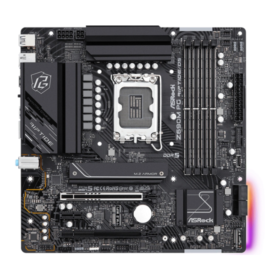
Page 14: Motherboard Layout
1.3 Motherboard Layout CPU_FAN2/WP USB 3.2 Gen1 CPU_FAN1 ATX12V1 ATX12V2 T: USB3_0 B: USB3_1 CHA_FAN3/WP BOOT DRAM USB 3.2 Gen1 T: USB3_2 B: USB3_3 BIOS _FB1 USB 3.2 Gen2 T: USB32_TA_1 B: USB32_TC_1 USB 3.2 Gen1 Top: T: USB3_4 RJ-45 B: USB3_5 CHA_FAN1/WP CHA_FAN2/WP... - Page 15 Z690M PG Riptide/D5 No. Description 8 pin 12V Power Connector (ATX12V1) 4 pin 12V Power Connector (ATX12V2) CPU Fan Connector (CPU_FAN1) 2 x 288-pin DDR5 DIMM Slots (DDR5_A1, DDR5_B1) 2 x 288-pin DDR5 DIMM Slots (DDR5_A2, DDR5_B2) Chassis/Water Pump Fan Connector (CHA_FAN3/WP)
-
Page 16: I/O Panel
1.4 I/O Panel No. Description No. Description 2.5G LAN RJ-45 Port* USB 3.2 Gen2 Type-C Port Line In (Light Blue)** (USB32_TC_1) Front Speaker (Lime)** BIOS Flashback Button Microphone (Pink)** USB 3.2 Gen1 Ports (USB3_2_3)*** USB 3.2 Gen1 Ports (USB3_4_5) DisplayPort 1.4 USB 3.2 Gen2 Type-A Port HDMI Port (USB32_TA_1)***... - Page 17 Z690M PG Riptide/D5 ** Function of the Audio Ports in 7.1-channel Configuration: Port Function Light Blue (Rear panel) Rear Speaker Out Lime (Rear panel) Front Speaker Out Pink (Rear panel) Central /Subwoofer Speaker Out Lime (Front panel) Side Speaker Out...
-
Page 18: Chapter 2 Installation
Chapter 2 Installation This is a Micro ATX form factor motherboard. Before you install the motherboard, study the configuration of your chassis to ensure that the motherboard fits into it. Pre-installation Precautions Take note of the following precautions before you install motherboard components or change any motherboard settings. -
Page 19: Installing The Cpu
Z690M PG Riptide/D5 2.1 Installing the CPU 1. Before you insert the 1700-Pin CPU into the socket, please check if the PnP cap is on the socket, if the CPU surface is unclean, or if there are any bent pins in the socket. Do not force to insert the CPU into the socket if above situation is found. - Page 21 Z690M PG Riptide/D5 Please save and replace the cover if the processor is removed. The cover must be placed if you wish to return the motherboard for after service.
-
Page 22: Installing The Cpu Fan And Heatsink
2.2 Installing the CPU Fan and Heatsink... -
Page 23: Installing Memory Modules (Dimm)
Z690M PG Riptide/D5 2.3 Installing Memory Modules (DIMM) This motherboard provides four 288-pin DDR5 (Double Data Rate 5) DIMM slots, and supports Dual Channel Memory Technology. 1. For dual channel configuration, you always need to install identical (the same brand, speed, size and chip-type) DDR5 DIMM pairs. -
Page 25: Expansion Slots (Pcie Slots)
Z690M PG Riptide/D5 2.4 Expansion Slots (PCIe Slots) There are 3 PCIe slots on the motherboard. Before installing an expansion card, please make sure that the power supply is switched off or the power cord is unplugged. Please read the documentation of the expansion card and make necessary hardware settings for the card before you start the installation. -
Page 26: Jumpers Setup
2.5 Jumpers Setup The illustration shows how jumpers are setup. When the jumper cap is placed on the pins, the jumper is “Short”. If no jumper cap is placed on the pins, the jumper is “Open”. Clear CMOS Jumper Short: Clear CMOS (CLRMOS1) Open: Default 2-pin Jumper... -
Page 27: Onboard Headers And Connectors
Z690M PG Riptide/D5 2.6 Onboard Headers and Connectors Onboard headers and connectors are NOT jumpers. Do NOT place jumper caps over these headers and connectors. Placing jumper caps over the headers and connectors will cause permanent damage to the motherboard. - Page 28 Serial ATA3 Connectors These four SATA3 Right Angle: connectors support SATA (SATA3_0: data cables for internal see p.6, No. 15) (Upper) storage devices with up to (SATA3_1: 6.0 Gb/s data transfer rate. see p.6, No. 15) (Lower) (SATA3_2: see p.6, No. 16) (Upper) (SATA3_3: see p.6, No.
- Page 29 Z690M PG Riptide/D5 Front Panel Audio Header This header is for PRESENCE# (9-pin HD_AUDIO1) MIC_RET connecting audio devices OUT_RET (see p.6, No. 25) to the front audio panel. OUT2_L J_SENSE OUT2_R MIC2_R MIC2_L 1. High Definition Audio supports Jack Sensing, but the panel wire on the chassis must support HDA to function correctly.
- Page 30 CPU Fan Connector This motherboard pro- FAN_SPEED_CONTROL CPU_FAN_SPEED (4-pin CPU_FAN1) vides a 4-Pin CPU fan +12V (see p.6, No. 3) (Quiet Fan) connector. If you plan to connect a 3-Pin CPU fan, please connect it to Pin 1-3. CPU/Water Pump Fan This motherboard pro- Connector vides a 4-Pin water cooling...
- Page 31 Z690M PG Riptide/D5 ATX 12V Power Please connect an ATX Connector 12V power supply to this (4-pin ATX12V2) connector. (see p.6, No. 2) *The power supply plug fits into this connector in only one orientation. *Connecting an ATX 12V 4-pin cable to ATX12V2 is optional.
- Page 32 RGB LED Header This RGB header is used to con- (4-pin RGB_LED1) nect RGB LED extension cable +12V G R (see p.6, No. 22) which allow users to choose from various LED lighting effects. Caution: Never install the RGB LED cable in the wrong orientation;...
-
Page 33: Smart Switch
(BIOS_FB1) users to flash the BIOS. (see p.8, No. 8) ASRock BIOS Flashback feature allows you to update BIOS without powering on the system, even without CPU. Before using the BIOS Flashback function, please suspend BitLocker and any encryption or security relying on the TPM. Make sure that you have already stored and backup-ed the recovery key. -
Page 34: Post Status Checker
2.8 Post Status Checker Post Status Checker (PSC) diagnoses the computer when users power on the machine. It emits a red light to indicate whether the CPU, memory, VGA or stor- age is dysfunctional. The lights go off if the four mentioned above are functioning normally. -
Page 35: Crossfire Tm Operation Guide
Z690M PG Riptide/D5 2.9 CrossFire Operation Guide This motherboard supports CrossFire that allows you to install up to two identical PCI Express x16 graphics cards. 1. You should only use identical CrossFire -ready graphics cards that are AMD certified. 2. Make sure that your graphics card driver supports AMD CrossFire technology. - Page 36 Step 3 Connect a VGA/DVI/DP/HDMI cable from the monitor to the corresponding port on the graphics card installed to the PCIE1 slot.
-
Page 37: Driver Installation And Setup
Z690M PG Riptide/D5 2.9.2 Driver Installation and Setup Step 1 Power on your computer and boot into OS. Step 2 Remove the AMD drivers if you have any VGA drivers installed in your system. The Catalyst Uninstaller is an optional download. We recommend using this utility to uninstall any previously installed Catalyst drivers prior to installation. -
Page 38: Wifi/Bt Pcie Wifi Module And Intel® Cnvi (Integrated Wifi/Bt) Installation Guide
2.10 M.2 WiFi/BT PCIe WiFi Module and Intel® CNVi (Integrated WiFi/BT) Installation Guide The M.2, also known as the Next Generation Form Factor (NGFF), is a small size and versatile card edge connector that aims to replace mPCIe and mSATA. The M.2 Socket (Key E) supports type 2230 WiFi/BT PCIe WiFi module and Intel®... - Page 39 Z690M PG Riptide/D5 Step 3 Gently insert the WiFi/BT PCIe WiFi module or Intel® CNVi (Integrated WiFi/BT) into the M.2 slot. Please be aware that the module only fits in one orientation. Step 4 Tighten the screw with a screwdriver to secure the module into place.
-
Page 40: M.2_Ssd (Ngff) Module Installation Guide (M2_1)
2.11 M.2_SSD (NGFF) Module Installation Guide (M2_1) The M.2, also known as the Next Generation Form Factor (NGFF), is a small size and versatile card edge connector that aims to replace mPCIe and mSATA. The Hyper M.2 Socket (M2_1, Key M) supports type 2260/2280 PCIe Gen4x4 (64 Gb/s) mode. Installing the M.2_SSD (NGFF) Module Step 1 Prepare a M.2_SSD (NGFF) module... - Page 41 Z690M PG Riptide/D5 Step 3 Before installing a M.2 (NGFF) SSD module, please loosen the screws to remove the M.2 heatsink. *Please remove the protective films on the bottom side of the M.2 heatsink before you install a M.2 SSD module.
- Page 42 Step 6 Tighten the screw with a screwdriver to secure the module and M.2 heatsink into place. Please do not overtighten the screw as this might damage the module and M.2 heatsink.
- Page 43 Z690M PG Riptide/D5 M.2_SSD (NGFF) Module Support List (M2_1) Vendor Interface ADATA PCIe3 x4 ASX7000NP-128GT-C ADATA PCIe3 x4 ASX8000NP-256GM-C ADATA PCIe3 x4 ASX7000NP-256GT-C ADATA PCIe3 x4 ASX8000NP-512GM-C ADATA PCIe3 x4 ASX7000NP-512GT-C Apacer PCIe3 x4 AP240GZ280 Corsair PCIe3 x4 CSSD-F240GBMP500 Intel...
-
Page 44: M.2_Ssd (Ngff) Module Installation Guide (M2_2)
2.12 M.2_SSD (NGFF) Module Installation Guide (M2_2) The M.2, also known as the Next Generation Form Factor (NGFF), is a small size and versatile card edge connector that aims to replace mPCIe and mSATA. The Hyper M.2 Socket (M2_2, Key M) supports type 2230/2242/2260/2280 SATA3 6.0 Gb/s & PCIe Gen4x4 (64 Gb/s) modes. - Page 45 Z690M PG Riptide/D5 Step 3 Move the standoff based on the module type and length. The standoff is placed at the nut location D by default. Skip Step 3 and 4 and go straight to Step 5 if you are going to use the default nut.
- Page 46 M.2_SSD (NGFF) Module Support List Vendor Interface ADATA SATA3 AXNS330E-32GM-B ADATA SATA3 AXNS381E-128GM-B ADATA SATA3 AXNS381E-256GM-B ADATA SATA3 ASU800NS38-256GT-C ADATA SATA3 ASU800NS38-512GT-C ADATA PCIe3 x4 ASX7000NP-128GT-C ADATA PCIe3 x4 ASX8000NP-256GM-C ADATA PCIe3 x4 ASX7000NP-256GT-C ADATA PCIe3 x4 ASX8000NP-512GM-C ADATA PCIe3 x4 ASX7000NP-512GT-C Apacer PCIe3 x4...
- Page 47 Z690M PG Riptide/D5 TEAM PCIe3 x4 TM8FP2240G0C101 TEAM PCIe3 x4 TM8FP2480GC110 Transcend SATA3 TS256GMTS400 Transcend SATA3 TS512GMTS600 Transcend SATA3 TS512GMTS800 V-Color SATA3 VLM100-120G-2280B-RD V-Color SATA3 VLM100-240G-2280RGB V-Color SATA3 VSM100-240G-2280 V-Color SATA3 VLM100-240G-2280B-RD SATA3 WDS100T1B0B-00AS40 SATA3 WDS240G1G0B-00RC30 PCIe3 x4 WDS256G1X0C-00ENX0 (NVME)
-
Page 48: Chapter 3 Software And Utilities Operation
Chapter 3 Software and Utilities Operation 3.1 Installing Drivers The Support CD that comes with the motherboard contains necessary drivers and useful utilities that enhance the motherboard’s features. Running The Support CD To begin using the support CD, insert the CD into your CD-ROM drive. The CD automatically displays the Main Menu if “AUTORUN”... -
Page 49: Asrock Motherboard Utility (Phantom Gaming Tuning)
Gaming Tuning) ASRock Motherboard Utility (Phantom Gaming Tuning) can be downloaded from ASRock Live Update & APP Shop. After the installation, you will find the icon “AS- Rock Motherboard Utility (Phantom Gaming Tuning)“ on your desktop. Double- click the “ASRock Motherboard Utility (Phantom Gaming Tuning)“... - Page 50 OC Tweaker Configurations for overclocking the system. System Info View information about the system. *The System Browser tab may not appear for certain models.
- Page 51 Settings Configure ASRock ASRock Motherboard Utility (Phantom Gaming Tuning). Click to select "Auto run at Windows Startup" if you want ASRock Motherboard Utility (Phantom Gaming Tuning) to be launched when you start up the Windows operating system.
-
Page 52: Asrock Live Update & App Shop
Double-click on your desktop to access ASRock Live Update & APP Shop utility. *You need to be connected to the Internet to download apps from the ASRock Live Update & APP Shop. 3.3.1 UI Overview Category Panel Hot News... -
Page 53: Apps
Z690M PG Riptide/D5 3.3.2 Apps When the "Apps" tab is selected, you will see all the available apps on screen for you to download. Installing an App Step 1 Find the app you want to install. The most recommended app appears on the left side of the screen. The other various apps are shown on the right. - Page 54 Step 3 If you want to install the app, click on the red icon to start downloading. Step 4 When installation completes, you can find the green "Installed" icon appears on the upper right corner. To uninstall it, simply click on the trash can icon *The trash icon may not appear for certain apps.
- Page 55 Z690M PG Riptide/D5 Upgrading an App You can only upgrade the apps you have already installed. When there is an available new version for your app, you will find the mark of "New Version" appears below the installed app icon.
-
Page 56: Bios & Drivers
3.3.3 BIOS & Drivers Installing BIOS or Drivers When the "BIOS & Drivers" tab is selected, you will see a list of recommended or critical updates for the BIOS or drivers. Please update them all soon. Step 1 Please check the item information before update. Click on to see more details. -
Page 57: Setting
Z690M PG Riptide/D5 3.3.4 Setting In the "Setting" page, you can change the language, select the server location, and determine if you want to automatically run the ASRock Live Update & APP Shop on Windows startup. -
Page 58: Nahimic Audio
3.4 Nahimic Audio Nahimic audio software provides an incredible high definition sound technology which boosts the audio and voice performance of your system. Nahimic Audio interface is composed of four tabs : Audio, Microphone, Sound Tracker and Settings. There are four functions in Nahimic audio : Function Description From this tab, you can mute the current audio device, choose... -
Page 59: Asrock Polychrome Sync
Z690M PG Riptide/D5 3.5 ASRock Polychrome SYNC ASRock Polychrome SYNC is a lighting control utility specifically designed for unique indi- viduals with sophisticated tastes to build their own stylish colorful lighting system. Simply by connecting the LED strip, you can customize various lighting schemes and patterns, including Static, Breathing, Strobe, Cycling, Music, Wave and more. - Page 60 Connecting the Addressable RGB LED Strip Connect your Addressable RGB LED strips to the Addressable LED Headers (ADDR_LED1 / ADDR_LED2 / ADDR_LED3) on the motherboard. ADDR_LED2 DO_ADDR VOUT ADDR_LED3 DO_ADDR VOUT ADDR_LED1 DO_ADDR VOUT 1. Never install the RGB LED cable in the wrong orientation; otherwise, the cable may be damaged.
- Page 61 ASRock Polychrome SYNC Utility Now you can adjust the RGB LED color through the ASRock Polychrome SYNC Utility. Download this utility from the ASRock Live Update & APP Shop and start coloring your PC style your way! Drag the tab to customize your preference.
-
Page 62: Chapter 4 Uefi Setup Utility
Chapter 4 UEFI SETUP UTILITY 4.1 Introduction This section explains how to use the UEFI SETUP UTILITY to configure your system. You may run the UEFI SETUP UTILITY by pressing <F2> or <Del> right after you power on the computer, otherwise, the Power-On-Self-Test (POST) will continue with its test routines. -
Page 63: Ez Mode
Z690M PG Riptide/D5 4.2 EZ Mode The EZ Mode screen appears when you enter the BIOS setup program by default. EZ mode is a dashboard which contains multiple readings of the system’s current status. You can check the most crucial information of your system, such as CPU speed, DRAM frequency, SATA information, fan speed, etc. -
Page 64: Advanced Mode
4.3 Advanced Mode The Advanced Mode provides more options to configure the BIOS settings. Refer to the following sections for the detailed configurations. To access the EZ Mode, press <F6> or click the "EZ Mode" button at the upper right corner of the screen. -
Page 65: Navigation Keys
Z690M PG Riptide/D5 4.3.2 Navigation Keys Use < > key or < > key to choose among the selections on the menu bar, and use < > key or < > key to move the cursor up or down to select items, then press <Enter>... -
Page 66: Main Screen
4.4 Main Screen When you enter the UEFI SETUP UTILITY, the Main screen will appear and display the system overview. The availability and location of BIOS settings can be different for different models and BIOS versions. My Favorite Display your collection of BIOS items. Press F5 to add/remove your favorite items. -
Page 67: Oc Tweaker Screen
Z690M PG Riptide/D5 4.5 OC Tweaker Screen In the OC Tweaker screen, you can set up overclocking features. Because the UEFI software is constantly being updated, the following UEFI setup screens and descriptions are for reference purpose only, and they may not exactly match what you see on your screen. - Page 68 The CPU speed is determined by the CPU P-Core Ratio multiplied with the BCLK. Increasing the CPU P-Core Ratio will increase the internal CPU clock speed without affecting the clock speed of other components. AVX2 Ratio Offset AVX2 Ratio Offset specifies a negative offset from the CPU Ratio for AVX workloads.
- Page 69 Z690M PG Riptide/D5 BCLK TSC HW Fixup BCLK TSC HW Fixup disable during TSC copy from PMA to APIC. FLL Overclock Mode Nominal is good for normal core ratio overclocking. Elevated and Extremely El¬evated are good for high BCLK OC.
- Page 70 Short Duration Power Limit Configure Package Power Limit 2 in watts. When the limit is exceeded, the CPU ratio will be lowered immediately. A lower limit can protect the CPU and save power, while a higher limit may improve performance. CPU Core Unlimited Current Limit To unlock voltage regulator current limit completely, you can set this option to Enabled.
- Page 71 Z690M PG Riptide/D5 BCLK Frequency Configure the BCLK Frequency. Primary Timing CAS# Latency (tCL) The time between sending a column address to the memory and the beginning of the data in response. RAS# to CAS# Delay (tRCD) The number of clock cycles required between the opening of a row of memory and accessing columns within it.
- Page 72 RAS to RAS Delay (tRRD_S) The number of clocks between two rows activated in different banks of the same rank. Write to Read Delay (tWTR_L) The number of clocks between the last valid write operation and the next read command to the same internal bank. Write to Read Delay (tWTR_S) The number of clocks between the last valid write operation and the next read command to the same internal bank.
- Page 73 Z690M PG Riptide/D5 tRDRD_sg Configure between module read to read delay. tRDRD_dg Configure between module read to read delay. tRDRD_dr Configure between module read to read delay. tRDRD_dd Configure between module read to read delay. tRDWR_sg Configure between module read to write delay.
- Page 74 tWRWR_dg Configure between module write to write delay. tWRWR_dr Configure between module write to write delay. tWRWR_dd Configure between module write to write delay. TAT Runtime Value tRDRD_sg Configure between module read to read delay. tRDRD_dg Configure between module read to read delay. tRDRD_dr Configure between module read to read delay.
- Page 75 Z690M PG Riptide/D5 tWRRD_dr Configure between module write to read delay. tWRRD_dd Configure between module write to read delay. tWRWR_sg Configure between module write to write delay. tWRWR_dg Configure between module write to write delay. tWRWR_dr Configure between module write to write delay.
- Page 76 Initial RTL (MC1 C1 B1/B2) Configure round trip latency initial value. RTL (MC0 C0 A1/A2) Configure round trip latency value. RTL (MC0 C1 A1/A2) Configure round trip latency value. RTL (MC1 C0 B1/B2) Configure round trip latency value. RTL (MC1 C1 B1/B2) Configure round trip latency value.
- Page 77 Z690M PG Riptide/D5 ODT NOM Rd (B2) Configure the memory on die termination resistors' NOM Rd for channel B2. ODT NOM Wr (A1) Configure the memory on die termination resistors' NOM Wr for channel A1. ODT NOM Wr (A2) Configure the memory on die termination resistors' NOM Wr for channel A2.
- Page 78 ODT CA (A1 Group A) Configure the memory on die termination resistors' CA for channel A1 Group A. ODT CA (A2 Group A) Configure the memory on die termination resistors' CA for channel A2 Group A. ODT CA (B1 Group A) Configure the memory on die termination resistors' CA for channel B1 Group A.
- Page 79 Z690M PG Riptide/D5 ODT CS (A2 Group B) Configure the memory on die termination resistors' CS for channel A2 Group B. ODT CS (B1 Group B) Configure the memory on die termination resistors' CS for channel B1 Group B. ODT CS (B2 Group B) Configure the memory on die termination resistors' CS for channel B2 Group B.
- Page 80 Try Slowest MRC Training. Realtime Memory Timing Configure the realtime memory timings. [Enabled] The system will allow performing realtime memory timing changes after MRC_DONE. Reset for MRC Failed Reset system after MRC training is failed. MRC Training on Warm Boot When enabled, memory training will be executed when warm boot.
- Page 81 Z690M PG Riptide/D5 +0.82V PCH Voltage Configure the chipset voltage (0.82V). +1.05V PCH Voltage Configure the chipset voltage (1.05V). VCCIN AUX Voltage Configure the voltage for the VCCIN AUX. +1.8V PROC Voltage Configure the CPU voltage (1.8V). +1.05V PROC Voltage Configure the CPU voltage (1.05V).
- Page 82 P-Core PLL Voltage Offset Use this feature to set the PLL Voltage Offset value from 0-15 with each unit at 17.5mV. This is used to increase the range of the domain frequency in extreme overclocking conditions. Enter 0 to use the manufacturer default value. E-Core PLL Voltage Offset Use this feature to set the PLL Voltage Offset value from 0-15 with each unit at 17.5mV.
- Page 83 Z690M PG Riptide/D5 Extra Turbo Voltage Specifies the extra turbo voltage applied while the IA Core is operating in turbo mode. VF Offset Mode Selects between Legacy and Selection modes. Need Reset System after enabling OverClocking Feature to initialize the default value. In Legacy Mode, setting a global offset for the entire VF curve.
- Page 84 Extra Turbo Voltage Specifies the extra turbo voltage applied while ring is operating in turbo mode. Uses Mailbox MSR 0x150, cmd 0x10, 0x11. Range 0-2000 mV. VF Offset Mode Selects between Legacy and Selection modes. Need Reset System after enabling OverClocking Feature to initialize the default value.
- Page 85 Z690M PG Riptide/D5 System Agent Voltage Offset Specifies the Offset Voltage applied to the Uncore domain. This voltage is specified in millivolts. Offset Prefix Sets the offset value as positive or negative. Save User Default Type a profile name and press enter to save your settings as user default.
-
Page 86: Advanced Screen
4.6 Advanced Screen In this section, you may set the configurations for the following items: CPU Configuration, Chipset Configuration, Storage Configuration, Intel(R) Thunderbolt, ACPI Configuration, USB Configuration and Trusted Computing. Setting wrong values in this section may cause the system to malfunction. UEFI Configuration UEFI Setup Style Select the default mode when entering the UEFI setup utility. -
Page 87: Cpu Configuration
Z690M PG Riptide/D5 4.6.1 CPU Configuration Processor E-Core Information This item displays the E-Core Information. Processor P-Core Information This item displays the P-Core Information. Intel Hyper Threading Technology Intel Hyper Threading Technology allows multiple threads to run on each core, so that the overall performance on threaded software is improved. - Page 88 C7 enabled for better power saving. Enhanced Halt State (C1E) Enable Enhanced Halt State (C1E) for lower power consumption. CPU C6 State Support Enable C6 deep sleep state for lower power consumption. CPU C7 State Support Enable C7 deep sleep state for lower power consumption. Package C State Support Enable CPU, PCIe, Memory, Graphics C State Support for power saving.
- Page 89 Z690M PG Riptide/D5 Legacy Game Compatibility Mode When enabled, pressing the scroll lock key will toggle the Efficient cores between being parked when Scroll Lock LED is on and un-parked when LED is off.
-
Page 90: Chipset Configuration
4.6.2 Chipset Configuration Primary Graphics Adapter Select a primary VGA. Above 4G Decoding Enable or disable 64bit capable Devices to be decoded in Above 4G Address Space (only if the system supports 64 bit PCI decoding). C.A.M (Clever Access Memory) If system has Resizable BAR capable PCIe Devices, use this option to enable or disable Resizable BAR support (only of the system supports 64-bit PCI decoding). - Page 91 Z690M PG Riptide/D5 DMI Link Speed Configure DMI Slot Link Speed. Auto mode is optimizing for overclocking. PCIE1 Link Speed Select the link speed for PCIE1. PCIE2 Link Speed Select the link speed for PCIE2. PCIE3 Link Speed Select the link speed for PCIE3.
- Page 92 Front Panel Enable/disable front panel HD audio. Onboard HDMI HD Audio Enable audio for the onboard digital outputs. Onboard WAN Device Use this item to enable or disable the onboard WAN device. Deep Sleep Configure deep sleep mode for power saving when the computer is shut down. Restore on AC/Power Loss Select the power state after a power failure.
-
Page 93: Storage Configuration
Z690M PG Riptide/D5 4.6.3 Storage Configuration SATA Controller(s) Enable/disable the SATA controllers. SATA Mode Selection AHCI: Supports new features that improve performance. Hybrid Storage Detection and Configuration Mode This item allows you select Hybrid Storage Detection and Configuration Mode. SATA Aggressive Link Power Management SATA Aggressive Link Power Management allows SATA devices to enter a low power state during periods of inactivity to save power. -
Page 94: Intel(R) Thunderbolt
4.6.4 Intel(R) Thunderbolt Discrete Thunderbolt(TM) Support Enable or disable the Discrete Thunderbolt(TM) Support. Thunderbolt Boot Support Enabled to allow booting from Bootable devices which are present behind Thunderbolt. Thunderbolt Usb Support Enabled to allow booting from Usb devices which are present behind Thunderbolt. Windows 10 Thunderbolt support Enable or disable the Windows 10 Thunderbolt support. -
Page 95: Acpi Configuration
Z690M PG Riptide/D5 4.6.5 ACPI Configuration Suspend to RAM Select disable for ACPI suspend type S1. It is recommended to select auto for ACPI S3 power saving. PCIE Devices Power On Allow the system to be waked up by a PCIE device and enable wake on LAN. -
Page 96: Usb Configuration
4.6.6 USB Configuration Legacy USB Support Enable or disable Legacy OS Support for USB 2.0 devices. If you encounter USB compatibility issues it is recommended to disable legacy USB support. Select UEFI Setup Only to support USB devices under the UEFI setup and Windows/Linux operating systems only. -
Page 97: Trusted Computing
Z690M PG Riptide/D5 4.6.7 Trusted Computing NOTE: Options vary depending on the version of your connected TPM module. Security Device Support Use this item to enable or disable BIOS support for security device. O.S. will not show Security Device. TCG EFI protocol and INT1A interface will not be available. - Page 98 NOTE: Your computer will reboot during restart in order to change State of the Device. Platform Hierarchy Use this item to enable or disable Platform Hierarchy. Storage Hierarchy Use this item to enable or disable Storage Hierarchy. Endorsement Hierarchy Use this item to enable or disable Endorsement Hierarchy. Physical Presence Spec version Select this item to tell OS to support PPI spec version 1.2 or 1.3.
-
Page 99: Tools
ASRock Polychrome RGB Select LED lighting color. UEFI Tech Service Contact ASRock Tech Service if you are having trouble with your PC. Please setup network configuration before using UEFI Tech Service. Easy RAID Installer Easy RAID Installer helps you to copy the RAID driver from the support CD to your USB storage device. - Page 100 Internet Flash - DHCP (Auto IP), Auto ASRock Internet Flash downloads and updates the latest UEFI firmware version from our servers for you. Please setup network configuration before using Internet Flash. *For BIOS backup and recovery purpose, it is recommended to plug in your USB pen drive before using this function.
-
Page 101: Hardware Health Event Monitoring Screen
Z690M PG Riptide/D5 4.8 Hardware Health Event Monitoring Screen This section allows you to monitor the status of the hardware on your system, including the parameters of the CPU temperature, motherboard temperature, fan speed and voltage. Fan Tuning Measure Fan Min Duty Cycle. - Page 102 CPU Fan 2 Control Mode Select DC/PWM mode for CPU Fan 2. CPU Fan 2 Setting Select a fan mode for CPU Fan 2, or choose Customize to set 5 CPU temperatures and assign a respective fan speed for each temperature. CPU Fan 2 Temp Source Select a fan temperature source for CPU Fan 2.
- Page 103 Z690M PG Riptide/D5 Chassis Fan 2 Setting Select a fan mode for Chassis Fan 2, or choose Customize to set 5 CPU temperatures and assign a respective fan speed for each temperature. Chassis Fan 2 Temp Source Select a fan temperature source for Chassis Fan 2.
- Page 104 Chassis Fan 4 Temp Source Select a fan temperature source for Chassis Fan 4. Chassis Fan 4 Step Up Set the value of Chassis Fan 4 Step Up. Chassis Fan 4 Step Down Set the value of Chassis Fan 4 Step Down.
-
Page 105: Security Screen
Z690M PG Riptide/D5 4.9 Security Screen In this section you may set or change the supervisor/user password for the system. You may also clear the user password. Supervisor Password Set or change the password for the administrator account. Only the administrator has authority to change the settings in the UEFI Setup Utility. -
Page 106: Boot Screen
4.10 Boot Screen This section displays the available devices on your system for you to configure the boot settings and the boot priority. Fast Boot Fast Boot minimizes your computer's boot time. In fast mode you may not boot from an USB storage device. The VBIOS must support UEFI GOP if you are using an external graphics card. - Page 107 Z690M PG Riptide/D5 Full Screen Logo Enable to display the boot logo or disable to show normal POST messages. AddOn ROM Display Enable AddOn ROM Display to see the AddOn ROM messages or configure the AddOn ROM if you've enabled Full Screen Logo. Disable for faster boot speed.
- Page 108 Launch Storage OpROM Policy Select UEFI only to run those that support UEFI option ROM only. Select Legacy only to run those that support legacy option ROM only. Select Do not launch to not execute both legacy and UEFI option ROM. Other PCI Device ROM Priority For PCI devices other than Network.
-
Page 109: Exit Screen
Z690M PG Riptide/D5 4.11 Exit Screen Save Changes and Exit When you select this option the following message, “Save configuration changes and exit setup?” will pop out. Select [OK] to save changes and exit the UEFI SETUP UTILITY. Discard Changes and Exit When you select this option the following message, “Discard changes and exit... - Page 110 Contact Information If you need to contact ASRock or want to know more about ASRock, you’re welcome to visit ASRock’s website at http://www.asrock.com; or you may contact your dealer for further information. For technical questions, please submit a support request form at http://www.asrock.com/support/tsd.asp...
- Page 111 13848 Magnolia Ave, Chino, CA91710 Phone/Fax No: +1-909-590-8308/+1-909-590-1026 hereby declares that the product Product Name : Motherboard Z690M PG Riptide/D5 Model Number : Conforms to the following speci cations: FCC Part 15, Subpart B, Unintentional Radiators Supplementary Information: is device complies with part 15 of the FCC Rules. Operation is subject to the...
- Page 112 EU Declaration of Conformity For the following equipment: Motherboard (Product Name) Z690M PG Riptide/D5 / ASRock (Model Designation / Trade Name) ASRock Incorporation (Manufacturer Name) 2F., No.37, Sec. 2, Jhongyang S. Rd., Beitou District, Taipei City 112, Taiwan (R.O.C.) (Manufacturer Address) EMC Directive –...
- Page 113 Ovaj dokument je originalno proizveden i objavljen od strane proizvođača, brenda ASRock, i preuzet je sa njihove zvanične stranice. S obzirom na ovu činjenicu, Tehnoteka ističe da ne preuzima odgovornost za tačnost, celovitost ili pouzdanost informacija, podataka, mišljenja, saveta ili izjava sadržanih u ovom dokumentu.
Need help?
Do you have a question about the Z690M PG RIPTIDE/D5 and is the answer not in the manual?
Questions and answers