
Related Manuals for ASROCK ROMED4ID-2T


Summary of Contents for ASROCK ROMED4ID-2T
- Page 1 ROMED4ID-2T User Manual Version 1.0 Published January 2021 Copyright©2021 ASRock Rack INC. All rights reserved.
- Page 2 (including damages for loss of profits, loss of business, loss of data, interruption of business and the like), even if ASRock Rack has been advised of the possibility of such damages arising from any defect or error in the documentation or product.
- Page 3 Contact Information If you need to contact ASRock Rack or want to know more about ASRock Rack, you’re welcome to visit ASRock Rack’s website at www.ASRockRack.com; or you may contact your dealer for further information. ASRock Rack Incorporation 6F., No.37, Sec. 2, Jhongyang S. Rd., Beitou District,...
-
Page 4: Table Of Contents
Contents Chapter 1 Introduction Package Contents Specifications Unique Features Motherboard Layout Onboard LED Indicators I/O Panel Block Diagram Chapter 2 Installation Screw Holes Pre-installation Precautions Installing the CPU Installation of Memory Modules (DIMM) Expansion Slot (PCI Express Slot) Onboard Headers and Connectors ATX PSU / DC-IN Power Connections Unit Identification purpose LED/Switch Driver Installation Guide... - Page 5 Main Screen Advanced Screen 3.3.1 CPU Configuration 3.3.2 Chipset Configuration 3.3.3 Storage Configuration 3.3.4 ACPI Configuration 3.3.5 USB Configuration 3.3.6 Super IO Configuration 3.3.7 Serial Port Console Redirection 3.3.8 H/W Monitor 3.3.9 PCI Subsystem Settings 3.3.10 AMD CBS 3.3.11 AMD PBS 3.3.12 PSP Firmware Versions 3.3.13 Instant Flash Server Mgmt...
- Page 6 Exit Screen Chapter 4 Software Support Install Operating System Support CD Information 4.2.1 Running The Support CD 4.2.2 Drivers Menu 4.2.3 Utilities Menu 4.2.4 Contact Information Chapter 5 Troubleshooting Troubleshooting Procedures Technical Support Procedures Returning Merchandise for Service...
-
Page 7: Chapter 1 Introduction
In case any modifications of this manual occur, the updated version will be available on ASRock Rack website without further notice. You may find the latest memory and CPU support lists on ASRock Rack website as well. ASRock Rack’s Website: www.ASRockRack.com If you require technical support related to this motherboard, please visit our website for specific information about the model you are using. -
Page 8: Specifications
Proprietary Dimension 6.7'' x 8.2'' (17.0 cm x 20.8 cm) Processor System AMD EPYC™ 7002* Series Processors Family *Please refer to CPU AVL on the ASRock Rack’s website for latest update. Socket Single Socket SP3 (LGA4094) Chipset System Memory Type... - Page 9 32MB AMI UEFI Legal BIOS BIOS Features - Plug and Play (PnP) - ACPI 2.0 Compliance Wake Up Events - SMBIOS 2.8 Support - ASRock Rack Instant Flash Hardware Monitor Temperature - CPU Temperature Sensing - MB/TR1/Card side Temperature Sensing...
- Page 10 Support OS Microsoft® Windows® - Server 2016 (64 bit) - Server 2019 (64 bit) Linux® - RedHat Enterprise Linux Server 8.2 (64 bit) / 7.9 (64 bit) - CentOs 8.2 (64 bit) / 7.9 (64 bit) - SUSE SLES 15.2 (64 bit) / 12.5 (64 bit) - UBuntu 20.04.1 (64 bit) / 18.04.5 (64 bit) / 16.04.7 (64 bit) Hypervisor - VMWare ESXi 6.7 u3 / 7.0 u1...
-
Page 11: Unique Features
POST or the <F2> key to enter into the BIOS setup menu to access ASRock Rack Instant Flash. Just launch this tool and save the new BIOS file to your USB flash drive, floppy disk or hard drive, then you can update your BIOS only in a few clicks without preparing an additional floppy diskette or other complicated flash utility. -
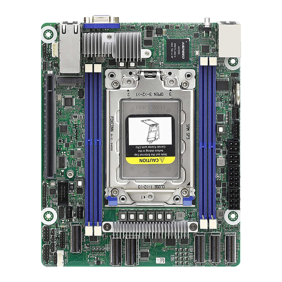
Page 12: Motherboard Layout
1.4 Motherboard Layout 20.8cm (8.2 in) BATTERY1 PSU_SMB1 FAN1 SLIM1 SATAPWR1 ATX12V2 ATX12V1 ATX4PIN1 DDR4_H1 (64 bit, 288-pin module) UID1 SLIM2 DDR4_G1 (64 bit, 288-pin module) SLIM3 2500 LGA4094 Socket SP3 SLIM4 SLIM5 DDR4_C1 (64 bit, 288-pin module) DDR4_D1 (64 bit, 288-pin module) FAN2 SLIM6 FAN3... - Page 13 ROMED4ID-2T Description System Fan Connector (FAN1) PSU SMBus Header (PSU_SMB1) SATA Power Connector (DC-IN Mode) (SATAPWR1)** ATX 4-PIN Power Connector (ATX4PIN1)** ATX 12V Power Connector (ATX12V2) ATX 12V Power Connector (ATX12V1) Slimline SAS Connector (SLIM1) (Supports SATA) Slimline SAS Connector (SLIM2)
-
Page 14: Onboard Led Indicators
1.5 Onboard LED Indicators DDR4_H1 (64 bit, 288-pin module) DDR4_G1 (64 bit, 288-pin module) LGA4094 Socket SP3 DDR4_D1 (64 bit, 288-pin module) DDR4_C1 (64 bit, 288-pin module) - Page 15 ROMED4ID-2T Item Status Description FAN_LED1 Amber FAN1 failed SB_PWR1 Green STB PWR ready FAN_LED3 Amber FAN3 failed FAN_LED2 Amber FAN2 failed BMC_LED1 Green BMC heartbeat LED...
-
Page 16: I/O Panel
1.6 I/O Panel No. Description No. Description USB 3.2 Gen1 Ports (USB3_1_2) VGA Port (VGA1) LAN RJ-45 Port (IPMI_LAN1)* 10G LAN RJ-45 Port (LAN1)** UID Switch (UID1) 10G LAN RJ-45 Port (LAN2)** *There are two LED next to the LAN port. Please refer to the table below for the LAN port LED indications. - Page 17 ROMED4ID-2T **There are two LEDs on each LAN port. Please refer to the table below for the LAN port LED indications. ACT/LINK LED SPEED LED LAN Port ACT/LINK LED SPEED LED 10G LAN Port (LAN1, LAN2) LED Indications Activity / Link LED...
-
Page 18: Block Diagram
1.7 Block Diagram... -
Page 19: Chapter 2 Installation
ROMED4ID-2T Chapter 2 Installation This is a Proprietary form factor (6.7'' x 8.2'', 17.0 cm x 20.8 cm) motherboard. Before you install the motherboard, study the configuration of your chassis to ensure that the motherboard fits into it. Make sure to unplug the power cord before installing or removing the motherboard. Failure to do so may cause physical injuries to you and damages to motherboard components. -
Page 20: Installing The Cpu
2.3 Installing the CPU 1. Before you insert the CPU into the socket, please check if the PnP cap is on the socket, if the CPU surface is unclean, or if there are any bent pins in the socket. Do not force to insert the CPU into the socket if above situation is found. - Page 21 ROMED4ID-2T...
- Page 22 Carr ier Frame with CPU Rail Frame Please make sure that the carrier frame with CPU is closely attached to the rail frame while inserting it. Install the carrier frame with CPU. Don’t separate them.
- Page 23 ROMED4ID-2T...
-
Page 24: Installation Of Memory Modules (Dimm)
2.4 Installation of Memory Modules (DIMM) This motherboard provides four 288-pin DDR4 (Double Data Rate 4) DIMM slots in two groups, and supports Quad Channel Memory Technology. Quad Channel Memory Configuration (without NVDIMM) DDR4_C1 DDR4_D1 DDR4_G1 DDR4_H1 Priority (Blue) (Blue) (Blue) (Blue) Populated... - Page 25 ROMED4ID-2T The DIMM only fits in one correct orientation. It will cause permanent damage to the motherboard and the DIMM if you force the DIMM into the slot at incorrect orientation.
-
Page 26: Expansion Slot (Pci Express Slot)
2.5 Expansion Slot (PCI Express Slot) There is 1 PCI Express slot on this motherboard. PCIE slot: PCIE7 (PCIE 4.0 x16 slot, from CPU) is used for PCI Express x16 lane width cards. Slot Generation Mechanical Electrical Source PCIE7 Installing an expansion card Step 1. -
Page 27: Onboard Headers And Connectors
ROMED4ID-2T 2.6 Onboard Headers and Connectors Onboard headers and connectors are NOT jumpers. Do NOT place jumper caps over these headers and connectors. Placing jumper caps over the headers and connectors will cause permanent damage to the motherboard. PLED+ System Panel Header... - Page 28 Auxiliary Panel Header This header supports multiple (9-pin ITX_AUX_PAN- functions on the front panel, LAN_LINK0_ACT EL1) including front panel SMB, LAN1_LINK_P LAN2_LINK_P (see p.6, No. 13) internet status indicator. LAN_LINK1_ACT SYSTEM_FAULT_LED_P SYSTEM_FAULT_LED_N R_CASEOPEN# USB 2.0 Header USB_PWR There is one USB (9-pin USB_1_2) 2.0 header on this DUMMY...
- Page 29 ROMED4ID-2T Slimline SAS Connectors These connectors are used for (SLIM1) the NVME PCIE devices. (see p.6, No. 7) SLIM1 (SLIM2) (see p.6, No. 8) SLIM2 (SLIM3) (see p.6, No. 10) SLIM3 (SLIM4) SLIM4 (see p.6, No. 11) (SLIM5) SLIM5 (see p.6, No. 12)
- Page 30 ATX 4-PIN Power The motherboard provides one Connector 4-pin power/signal connector ATX_PWROK (4-pin ATX4PIN1 which is a required input for PSON# ATX_+5VSB ATX power source. (ATX 24pin-to-4pin) (see p.6, No. 4) When using ATX power, it is necessary to use a 24pin-to- 4pin power cable to connect between the 24pin power connector of PSU and the...
- Page 31 ROMED4ID-2T ATX 12V Power The motherboard provides two Connectors 8-pin 12V power connectors (8-pin ATX12V1) which are required input for (see p.6, No. 6) either DC-IN 12V or ATX (8-pin ATX12V2) +12V power source. (see p.6, No. 5) When using ATX power, it is...
- Page 32 Intelligent Platform IPMB_SDA This 4-pin connector is used IPMB_SCL Management Bus Header to provide a cabled base-board (4-pin IPMB1) or front panel connection for (see p.6, No. 29) value added features and 3rd- No Connect party add-in cards, such as Emergency Management cards, t h a t p r o v i d e m a n a g e m e n t features using the IPMB.
-
Page 33: Atx Psu / Dc-In Power Connections
ROMED4ID-2T 2.7 ATX PSU / DC-IN Power Connections This motherboard supports both +12V DC and ATX power input. Please refer to the table below for the required connections between the motherboard and the power supply. Connector DC-IN ATX PSU 12V 8pin... -
Page 34: Unit Identification Purpose Led/Switch
2.8 Unit Identification purpose LED/Switch With the UID button, You are able to locate the server you’re working on from behind a rack of servers. Unit Identification When the UID button on the purpose LED/Switch front or rear panel is pressed, (UID1) the front/rear UID blue LED indicator will be truned on. - Page 35 ROMED4ID-2T 2.10 M.2_SSD (NGFF) Module Installation Guide (M2_1) The M.2, also known as the Next Generation Form Factor (NGFF), is a small size and versatile card edge connector that aims to replace mPCIe and mSATA. This M.2_SSD (NGFF) Socket 3 can accommodate a SATA3 6.0 Gb/s module or a PCI Express module up to Gen4 x4 (64 Gb/s) only.
-
Page 36: Chapter 3 Uefi Setup Utility
Chapter 3 UEFI Setup Utility 3.1 Introduction This section explains how to use the UEFI SETUP UTILITY to configure your system. The UEFI chip on the motherboard stores the UEFI SETUP UTILITY. You may run the UEFI SETUP UTILITY when you start up the computer. Please press <F2> or <Del> during the Power-On-Self-Test (POST) to enter the UEFI SETUP UTILITY;... -
Page 37: Navigation Keys
ROMED4ID-2T 3.1.2 Navigation Keys Please check the following table for the function description of each navigation key. Navigation Key(s) Function Description Moves cursor left or right to select Screens Moves cursor up or down to select items + / - To change option for the selected items <Tab>... -
Page 38: Main Screen
3.2 Main Screen Once you enter the UEFI SETUP UTILITY, the Main screen will appear and display the system overview. The Main screen provides system overview information and allows you to set the system time and date. -
Page 39: Advanced Screen
ROMED4ID-2T 3.3 Advanced Screen In this section, you may set the configurations for the following items: CPU Configuration, Chipset Configuration, Storage Configuration, ACPI Configuration, USB Configuration, Super IO Configuration, Serial Port Console Redirection, H/W Monitor, PCI Subsystem Settings, AMD CBS, AMD PBS, PSP Firmware Versions and Instant Flash. -
Page 40: Cpu Configuration
3.3.1 CPU Configuration SVM Mode Enable or disable CPU Virtualization. Node 0 Information View Memory Information related to Node 0. -
Page 41: Chipset Configuration
ROMED4ID-2T 3.3.2 Chipset Configuration OnBrd/Ext VGA Select Select between onboard or external VGA support. SLIMLINE1 Mode This allows you to configure SLIMLINE1 Mode. SLIMLINE2 Mode This allows you to configure SLIMLINE2 Mode. SLIMLINE4/SLIMLINE1 Link Width This allows you to select SLIMLINE4/SLIMLINE1 Link Width. - Page 42 PCIE7 Link Width This allows you to select PCIE7 Link Width. The default value is [x16]. Onboard Debug Port LED Enable or disable the onboard Dr. Debug LED. Restore AC Power Loss This allows you to set the power state after a power failure. If [Power Off] is selected, the power will remain off when the power recovers.
-
Page 43: Storage Configuration
ROMED4ID-2T 3.3.3 Storage Configuration SATA Hot Plug Enable/disable the SATA Hot Plug Function. -
Page 44: Acpi Configuration
3.3.4 ACPI Configuration PCIE Devices Power On Allow the system to be waked up by a PCIE device and enable wake on LAN. RTC Alarm Power On Use this item to enable or disable RTC (Real Time Clock) to power on the system. -
Page 45: Usb Configuration
ROMED4ID-2T 3.3.5 USB Configuration Legacy USB Support Use this option to enable or disable legacy support for USB devices. The default value is [Enabled]. -
Page 46: Super Io Configuration
3.3.6 Super IO Configuration Serial Port 1 Configuration Use this item to set parameters of Serial Port 1 (COM1). Serial Port Use this item to enable or disable the serial port. Serial Port Address Use this item to select an optimal setting for Super IO device. SOL Configuration Use this item to set parameters of SOL. -
Page 47: Serial Port Console Redirection
ROMED4ID-2T 3.3.7 Serial Port Console Redirection COM1 / SOL Console Redirection Use this option to enable or disable Console Redirection. If this item is set to Enabled, you can select a COM Port to be used for Console Redirection. Console Redirection Settings Use this option to configure Console Redirection Settings, and specify how your computer and the host computer to which you are connected exchange information. - Page 48 Bits Per Second Use this item to select the serial port transmission speed. The speed used in the host computer and the client computer must be the same. Long or noisy lines may require lower transmission speed. The options include [9600], [19200], [38400], [57600] and [115200]. Data Bits Use this item to set the data transmission size.
- Page 49 ROMED4ID-2T Redirect After POST When Bootloader is selected, then Legacy Console Redirection is disabled before booting to legacy OS. When Always Enable is selected, then Legacy Console Redirection is enabled for legacy OS. Default setting for this option is set to Always Enable.
-
Page 50: H/W Monitor
3.3.8 H/W Monitor In this section, it allows you to monitor the status of the hardware on your system, includ- ing the parameters of the CPU temperature, motherboard temperature, CPU fan speed, chassis fan speed, and the critical voltage. Watch Dog Timer This allows you to enable or disable the Watch Dog Timer. -
Page 51: Pci Subsystem Settings
ROMED4ID-2T 3.3.9 PCI Subsystem Settings Above 4G Decoding Enable or disable 64bit capable Devices to be decoded in Above 4G Address Space (only if the system supports 64 bit PCI decoding). SR-IOV Support If system has SR-IOV capable PCIe Devices, this option Enables or Disables Single Root IO... -
Page 52: Amd Cbs
3.3.10 AMD CBS CPU Common Options Use this item to configure CPU Common options. DF Common Options Use this item to configure DF Common options. UMC Common Options Use this item to configure UMC Common options. NBIO Common Options Use this item to configure NBIO Common options. FCH Common Options Use this item to configure FCH Common options. -
Page 53: Amd Pbs
ROMED4ID-2T 3.3.11 AMD PBS Use this item to configure AMD CPM RAS related settings. -
Page 54: Psp Firmware Versions
3.3.12 PSP Firmware Versions The PSP Firmware Verions displays the version information of PSP Recovery BL, PSP BootLoader, SMU FW, ABL, APCB, APDB, and APPB. -
Page 55: Instant Flash
ROMED4ID-2T 3.3.13 Instant Flash Instant Flash is a UEFI flash utility embedded in Flash ROM. This convenient UEFI update tool allows you to update system UEFI without entering operating systems ® first like MS-DOS or Windows . Just save the new UEFI file to your USB flash drive,... -
Page 56: Server Mgmt
3.4 Server Mgmt Wait For BMC Wait For BMC response for specified time out. BMC starts at the same time when BIOS starts during AC power ON. It takes around 90 seconds to initialize Host to BMC interfaces. -
Page 57: System Event Log
ROMED4ID-2T 3.4.1 System Event Log SEL Components Change this to enable ro disable event logging for error/progress codes during boot. Erase SEL Use this to choose options for earsing SEL. When SEL is Full Use this to choose options for reactions to a full SEL. -
Page 58: Bmc Network Configuration
3.4.2 BMC Network Configuration BMC Out of Band Access Enabled/Disabled BMC Out of band Access. Lan Channel (Failover) Manual Setting IPMI LAN If [No] is selected, the IP address is assigned by DHCP. If you prefer using a static IP address, toggle to [Yes], and the changes take effect after the system reboots. - Page 59 ROMED4ID-2T The default login information for the IPMI web interface is: Username: admin Password: admin For more instructions on how to set up remote control environment and use the IPMI man- agement platform, please refer to the IPMI Configuration User Guide or go to the Support website at: http://www.asrockrack.com/support/ipmi.asp...
-
Page 60: Bmc Tools
3.4.3 BMC Tools Load BMC Default Settings Use this item to Load BMC Default Settings. KCS Control Select this KCS interface state after POST end. If [Enabled] us selected, the BMC will remain KCS interface after POST stage. If [Disabled] is selected, the BMC will disable KCS interface after POST stage. -
Page 61: Security
ROMED4ID-2T 3.5 Security In this section, you may set or change the supervisor/user password for the system. For the user password, you may also clear it. Supervisor Password Set or change the password for the administrator account. Only the administrator has authority to change the settings in the UEFI Setup Utility. -
Page 62: Key Management
3.5.1 Key Management In this section, expert users can modify Secure Boot Policy variables without full authenti- cation. Factory Key Provision Install factory default Secure Boot keys after the platform reset and while the System is in Setup mode. Install Default Secure Boot Keys Please install default secure boot keys if it’s the first time you use secure boot. - Page 63 ROMED4ID-2T b) EFI_CERT_X509 (DER) c) EFI_CERT_RSA2048 (bin) d) EFI_CERT_SHAXXX 2. Authenticated UEFI Variable 3. EFI PE/COFF Image(SHA256) Key Source: Default, External, Mixed Key Exchange Keys Enroll Factory Defaults or load certificates from a file: 1. Public Key Certificate in: a) EFI_SIGNATURE_LIST...
- Page 64 1. Public Key Certificate in: a) EFI_SIGNATURE_LIST b) EFI_CERT_X509 (DER) c) EFI_CERT_RSA2048 (bin) d) EFI_CERT_SHAXXX 2. Authenticated UEFI Variable 3. EFI PE/COFF Image(SHA256) Key Source: Default, External, Mixed Authorized TimeStamps Enroll Factory Defaults or load certificates from a file: 1. Public Key Certificate in: a) EFI_SIGNATURE_LIST b) EFI_CERT_X509 (DER) c) EFI_CERT_RSA2048 (bin)
-
Page 65: Boot Screen
ROMED4ID-2T 3.6 Boot Screen In this section, it will display the available devices on your system for you to configure the boot settings and the boot priority. Boot Option #1 Use this item to set the system boot order. Boot Option #2 Use this item to set the system boot order. - Page 66 USB Device BBS Priorities Use this item to set the boot priorities for USB devices. Setup Prompt Timeout Configure the number of seconds to wait for the UEFI setup utility. Bootup Num-Lock If this item is set to [On], it will automatically activate the Numeric Lock function after boot-up.
-
Page 67: Csm Parameters
ROMED4ID-2T 3.6.1 CSM Parameters Enable to launch the Compatibility Support Module. Please do not disable unless you’re running a WHCK test. If you are using Windows Server 2012 R2 or later ver- sions 64-bit UEFI and all of your devices support UEFI, you may also disable CSM for faster boot speed. - Page 68 SLIMLINE2-1 Slot OpROM Use this item to select slot storage and Network Option ROM policy. In Auto option, the default is Disabled with NVMe device, but it is Legacy with other devices. (This item can't select Video Option ROM policy.) SLIMLINE2-2 Slot OpROM Use this item to select slot storage and Network Option ROM policy.
- Page 69 ROMED4ID-2T SLIMLINE6-1 Slot OpROM Use this item to select slot storage and Network Option ROM policy. In Auto option, the default is Disabled with NVMe device, but it is Legacy with other devices. (This item can't select Video Option ROM policy.) SLIMLINE6-2 Slot OpROM Use this item to select slot storage and Network Option ROM policy.
-
Page 70: Event Logs
3.7 Event Logs Change Smbios Event Log Settings This allows you to configure the Smbios Event Log Settings. When entering the item, you will see the followings: Smbios Event Log Use this item to enable or disable all features of the SMBIOS Event Logging during system boot. - Page 71 ROMED4ID-2T entries which utilize a multiple-event counter. The value ranges from 0 to 99 minutes. Log EFI Status Code Enable or disable the logging of EFI Status Codes as OEM reserved type E0 (if not already converted to legacy). Convert EFI Status Codes to Standard Smbios Type Enable or disable the converting of EFI Status Codes to Standard Smbios Types (Not all may be translated).
-
Page 72: Exit Screen
3.8 Exit Screen Save Changes and Exit When you select this option, the following message “Save configuration changes and exit setup?” will pop-out. Press <F10> key or select [Yes] to save the changes and exit the UEFI SETUP UTILITY. Discard Changes and Exit When you select this option, the following message “Discard changes and exit setup?”... -
Page 73: Chapter 4 Software Support
4.2.4 Contact Information If you need to contact ASRock Rack or want to know more about ASRock Rack, welcome to visit ASRock Rack’s website at http://www.ASRockRack.com; or you may contact your... -
Page 74: Chapter 5 Troubleshooting
Chapter 5 Troubleshooting 5.1 Troubleshooting Procedures Follow the procedures below to troubleshoot your system. Always unplug the power cord before adding, removing or changing any hardware com- ponents. Failure to do so may cause physical injuries to you and damages to motherboard components. - Page 75 1. Verify if the battery on the motherboard provides ~3VDC. Install a new battery if it does not. 2. Confirm whether your power supply provides adaquate and stable power. Other problems... 1. Try searching keywords related to your problem on ASRock Rack’s FAQ page: http://www.asrockrack.com/support...
-
Page 76: Technical Support Procedures
5.2 Technical Support Procedures If you have tried the troubleshooting procedures mentioned above and the problems are still unsolved, please contact ASRock Rack’s technical support with the following information: 1. Your contact information 2. Model name, BIOS version and problem type.
Need help?
Do you have a question about the ROMED4ID-2T and is the answer not in the manual?
Questions and answers