
Related Manuals for ASROCK ROMED8QM-2T


Summary of Contents for ASROCK ROMED8QM-2T
- Page 1 ROMED8QM-2T User Manual Version 1.0 Published February2020 Copyright©2020 ASRock Rack INC. All rights reserved.
- Page 2 (including damages for loss of profits, loss of business, loss of data, interruption of business and the like), even if ASRock Rack has been advised of the possibility of such damages arising from any defect or error in the documentation or product.
- Page 3 Contact Information If you need to contact ASRock Rack or want to know more about ASRock Rack, you’re welcome to visit ASRock Rack’s website at www.ASRockRack.com; or you may contact your dealer for further information. ASRock Rack Incorporation 6F., No.37, Sec. 2, Jhongyang S. Rd., Beitou District,...
-
Page 4: Table Of Contents
Contents Chapter 1 Introduction Package Contents Specifications Unique Features Motherboard Layout Onboard LED Indicators I/O Panel Block Diagram Chapter 2 Installation Screw Holes Pre-installation Precautions Installing the CPU Installation of Memory Modules (DIMM) Expansion Slots (PCI Express Slots) Jumper Setup Onboard Headers and Connectors Dr. - Page 5 3.1.2 Navigation Keys Main Screen Advanced Screen 3.3.1 CPU Configuration 3.3.2 Chipset Configuration 3.3.3 Storage Configuration 3.3.4 ACPI Configuration 3.3.5 USB Configuration 3.3.6 Super IO Configuration 3.3.7 Serial Port Console Redirection 3.3.8 H/W Monitor 3.3.9 AMD CBS 3.3.10 AMD PBS 3.3.11 PSP Firmware Versions 3.3.12 Instant Flash Server Mgmt...
- Page 6 Exit Screen Chapter 4 Software Support Install Operating System Support CD Information 4.2.1 Running The Support CD 4.2.2 Drivers Menu 4.2.3 Utilities Menu 4.2.4 Contact Information Chapter 5 Troubleshooting Troubleshooting Procedures Technical Support Procedures Returning Merchandise for Service...
-
Page 7: Chapter 1 Introduction
In case any modifications of this manual occur, the updated version will be available on ASRock Rack website without further notice. You may find the latest memory and CPU support lists on ASRock Rack website as well. ASRock Rack’s Website: www.ASRockRack.com If you require technical support related to this motherboard, please visit our website for specific information about the model you are using. -
Page 8: Specifications
1.2 Specifications ROMED8QM-2T MB Physical Status Form Factor Dimension 12'' x 9.6'' (30.5 cm x 24.4 cm) Processor System AMD EPYC™ 7002 Series Processor Family (ROME) Socket Single Socket SP3 (LGA4094) Chipset System Memory Type - Eight Channel DDR4 memory technology... - Page 9 ROMED8QM-2T LAN Controller - 2 x RJ45 10G base-T by Intel® X550-AT2 - 1 x RJ45 Dedicated IPMI LAN port by RTL8211E - Supports Wake-On-LAN - Supports Energy E_cient Ethernet 802.3az - Supports Dual LAN with Teaming function - Supports PXE...
- Page 10 32MB AMI UEFI Legal BIOS BIOS Features - Plug and Play (PnP) - ACPI 2.0 Compliance Wake Up Events - SMBIOS 2.8 Support - ASRock Rack Instant Flash Hardware Monitor Temperature - CPU / RTL8211E/X550 Environment Temperature Sensing - MB_A/MB_B/Card Side Temperature Sensing...
-
Page 11: Unique Features
POST or the <F2> key to enter into the BIOS setup menu to access ASRock Rack Instant Flash. Just launch this tool and save the new BIOS file to your USB flash drive, floppy disk or hard drive, then you can update your BIOS only in a few clicks without preparing an additional floppy diskette or other complicated flash utility. -
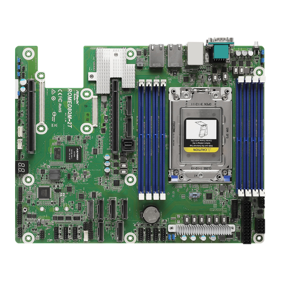
Page 12: Motherboard Layout
(Support SATA) SLIM2 (Support SATA) SLIM6 SATA_0_3 PCIE6 Intel SLIM7 SLIM4 X550 SATA_SGPIO2 SATA_SGPIO1 M2_1 MEZZ_B1 SATA_SGPIO3 CPU1_HSBP1 2500 FAN2 NUT30 ROMED8QM-2T FAN3 NUT42 FAN4 RoHS NCT6779 NUT60 MEZZ_A1 SATA_SGPIO0 CLRMOS1 PCIE1 NUT80 PANEL1 IPMB1 BMC_SMB1 AUX_PANEL1 TPM1 PLED PWRBTN CHASSIS_ID1... - Page 13 ROMED8QM-2T Description NVDIMM Power Mode Jumper (NV_12V_2) NVDIMM Power Mode Jumper (NV_12V_4) PSU SMBus Header (PSU_SMB1) ATX 12V Power Connector (ATX12V1) ATX Power Connector (ATXPWR1) USB 3.1 Gen1 Header (USB3_3_4) PWM Configuration Header (PWM_CFG1) NVDIMM Power Mode Jumper (NV_12V_1) NVDIMM Power Mode Jumper (NV_12V_3)
- Page 14 Description Intelligent Platform Management Bus Header (IPMB1) Manufacturing Mode Jumper (MFG1) Non Maskable Interrupt Button (NMI_BTN1) NCSI Mode Jumper (NCSI_SEL1) Thermal Sensor Header (TR1) Chassis ID Jumper (CHASSIS_ID2) Chassis ID Jumper (CHASSIS_ID1) Chassis ID Jumper (CHASSIS_ID0) PCI Express 4.0 Card Slot (PCIE1) Mezzanine Card Slot (MEZZ_A1) Mezzanine Card Slot (MEZZ_B1) PCI Express 4.0 Card Slot (PCIE6)
-
Page 15: Onboard Led Indicators
ROMED8QM-2T 1.5 Onboard LED Indicators DDR4_H1 (64 bit, 288-pin module) DDR4_G1 (64 bit, 288-pin module) DDR4_F1 (64 bit, 288-pin module) DDR4_E1 (64 bit, 288-pin module) LGA4094 Socket SP3 DDR4_A1 (64 bit, 288-pin module) DDR4_B1 (64 bit, 288-pin module) DDR4_C1 (64 bit, 288-pin module) - Page 16 Item Status Description LED_FAN7 FAN7 failed LED_FAN5 FAN5 failed LED_FAN6 FAN6 failed LED_FAN1 FAN1 failed LED_FAN2 FAN2 failed LED_FAN3 FAN3 failed LED_FAN4 FAN4 failed SB_PWR1 Green STB PWR ready BMC_LED1 Green BMC heartbeat LED...
-
Page 17: I/O Panel
ROMED8QM-2T 1.6 I/O Panel No. Description No. Description UID Switch (UID1) LAN RJ-45 Port (IPMI_LAN1)* VGA Port (VGA1) 10G LAN RJ-45 Port (LAN1)** Serial Port (COM1) 10G LAN RJ-45 Port (LAN2)** USB 3.1 Gen1 Ports (USB3_1_2) *There are two LED next to the LAN port. Please refer to the table below for the LAN port LED indications. - Page 18 **There are two LEDs on each LAN port. Please refer to the table below for the LAN port LED indications. ACT/LINK LED SPEED LED LAN Port LAN Port (LAN1, LAN2) LED Indications Activity / Link LED Speed LED Status Description Status Description No Link...
-
Page 19: Block Diagram
ROMED8QM-2T 1.7 Block Diagram MAC1 Ethernet 1.1 & PCI-Express 10/100/1000 PCIE Gen2 x 1 DDR4 DDR4 DDR4 DDR4 USB2.0 x 2 PCI-E Gen4 DDR4 DDR4 DDR4 DDR4 SATA Gen3 x 1... -
Page 20: Chapter 2 Installation
Chapter 2 Installation This is an ATX form factor (12” x 9.6”, 30.5 cm x 24.4 cm) motherboard. Before you install the motherboard, study the configuration of your chassis to ensure that the motherboard fits into it. Make sure to unplug the power cord before installing or removing the motherboard. Failure to do so may cause physical injuries to you and damages to motherboard components. -
Page 21: Pre-Installation Precautions
ROMED8QM-2T Do not over-tighten the screws! Doing so may damage the motherboard. 2.2 Pre-installation Precautions Take note of the following precautions before you install motherboard components or change any motherboard settings. 1. Unplug the power cord from the wall socket before touching any components. -
Page 22: Installing The Cpu
2.3 Installing the CPU 1. Before you insert the CPU into the socket, please check if the PnP cap is on the socket, if the CPU surface is unclean, or if there are any bent pins in the socket. Do not force to insert the CPU into the socket if above situation is found. - Page 23 ROMED8QM-2T...
- Page 24 Carr ier Frame with CPU Rail Frame Please make sure that the carrier frame with CPU is closely attached to the rail frame while inserting it. Install the carrier frame with CPU. Don’t separate them.
- Page 25 ROMED8QM-2T...
-
Page 26: Installation Of Memory Modules (Dimm)
2.4 Installation of Memory Modules (DIMM) This motherboard provides eight 288-pin DDR4 (Double Data Rate 4) DIMM slots in two groups, and supports Eight Channel Memory Technology. CPU1 1 DIMM 2 DIMMS 4 DIMMS 8 DIMMS 1. It is not allowed to install a DDR, DDR2 or DDR3 memory module into a DDR4 slot; otherwise, this motherboard and DIMM may be damaged. - Page 27 ROMED8QM-2T The DIMM only fits in one correct orientation. It will cause permanent damage to the motherboard and the DIMM if you force the DIMM into the slot at incorrect orientation.
-
Page 28: Expansion Slots (Pci Express Slots)
2.5 Expansion Slots (PCI Express Slots) There are 2 PCI Express slots on this motherboard. PCIE slot: PCIE1 (PCIE 4.0 x16 slot, from CPU) is used for PCI Express x16 lane width cards. PCIE6 (PCIE 4.0 x16 slot, from CPU) is used for PCI Express x16 lane width cards. Slot Generation Mechanical... -
Page 29: Jumper Setup
ROMED8QM-2T 2.6 Jumper Setup The illustration shows how jumpers are setup. When the jumper cap is placed on the pins, the jumper is “Short”. If no jumper cap is placed on the pins, the jumper is “Open”. The illustration shows a 3-pin jumper whose pin1 and pin2 are “Short”... - Page 30 Chassis ID0 Jumper (3-pin CHASSIS_ID0) (see p.6, No. 41) Chassis ID1 Jumper (3-pin CHASSIS_ID1) (see p.6, No. 40) Chassis ID2 Jumper (3-pin CHASSIS_ID2) Reserved for system level Reserved for system level (see p.6, No. 39) Chassis ID0 Jumper (3-pin CHASSIS_ID0) (see p.6, No.
- Page 31 ROMED8QM-2T NVDIMM Power Mode Jumpers (3-pin NV_12V_3) No Power (Default) +12V for NVDIMM_ABCD (see p.6, No. 9) NVDIMM Power Mode Jumpers (3-pin NV_12V_4) No Power (Default) +12V for NVDIMM_EFGH (see p.6, No. 2) The illustration shows how jumpers are setup. When the jumper cap is placed on the pins, the jumper is “Short”.
-
Page 32: Onboard Headers And Connectors
2.7 Onboard Headers and Connectors Onboard headers and connectors are NOT jumpers. Do NOT place jumper caps over these headers and connectors. Placing jumper caps over the headers and connectors will cause permanent damage to the motherboard. System Panel Header C onnec t t he power sw itch, PLED+ PLED-... - Page 33 ROMED8QM-2T Auxiliary Panel Header This header supports multiple (18-pin AUX_PANEL1) functions on the front panel, (see p.6, No. 28) including the front panel SMB, internet status indicator and chassis intrusion pin. A. Front panel SMBus connecting pin (6-1 pin FPSMB) This header allows you to connect SMBus (System Management Bus) equipment.
- Page 34 Mini-SAS HD Connector The connector supports SA TA _0_3 (SATA_0_3) MiniSAS-to-SATA (see p.6, No. 48) data cables for internal storage devices with up SA TA _4_7 to 6.0 Gb/s data transfer rate. IntA_PA_D+ USB 3.1 Gen1 Header Besides two default USB 3.1 IntA_PA_D- (19-pin USB3_3_4) Gen1 ports on the I/O panel,...
- Page 35 ROMED8QM-2T ATX Power Connector This motherboard provides a (24-pin ATXPWR1) 24-pin ATX power connector. (see p.6, No. 5) To use a 20-pin ATX power supply, please plug it along Pin 1 and Pin 13. ATX 12V Power This motherboard provides...
- Page 36 Baseboard Management The header is used for the SM Controller SMBus Header BUS devices. BMC_SMB_PRESENT_1_N (5-pin BMC_SMB1) Power (see p.6, No. 33) BMC_SMBCLK BMC_SMBDATA Thermal Sensor Header Please connect the thermal (3-pin TR1) sensor cable to either pin 1-2 (see p.6, No. 38) or pin 2-3 and the other end to the device which you wish to monitor its temperature.
- Page 37 ROMED8QM-2T PWM Configuration This header is used for PWM Header configurations. (3-pin PWM_CFG1) (see p.6, No. 7) Backplane PCI Express This header is used for the hot Hot-Plug Connector plug feature of HDDs on the (5-pin CPU1_HSBP1) backplane. P0_HP_ALERT_L (see p.6, No. 21)
-
Page 38: Dr. Debug
2.8 Dr. Debug Dr. Debug is used to provide code information, which makes troubleshooting even easier. Please see the diagrams below for reading the Dr. Debug codes. Code Description 0x10 PEI_CORE_STARTED 0x11 PEI_CAR_CPU_INIT 0x15 PEI_CAR_NB_INIT 0x19 PEI_CAR_SB_INIT 0x31 PEI_MEMORY_INSTALLED 0x32 PEI_CPU_INIT 0x33 PEI_CPU_CACHE_INIT... - Page 39 ROMED8QM-2T 0x63 DXE_CPU_INIT 0x68 DXE_NB_HB_INIT 0x69 DXE_NB_INIT 0x6A DXE_NB_SMM_INIT 0x70 DXE_SB_INIT 0x71 DXE_SB_SMM_INIT 0x72 DXE_SB_DEVICES_INIT 0x78 DXE_ACPI_INIT 0x79 DXE_CSM_INIT 0x90 DXE_BDS_STARTED 0x91 DXE_BDS_CONNECT_DRIVERS 0x92 DXE_PCI_BUS_BEGIN 0x93 DXE_PCI_BUS_HPC_INIT 0x94 DXE_PCI_BUS_ENUM 0x95 DXE_PCI_BUS_REQUEST_RESOURCES 0x96 DXE_PCI_BUS_ASSIGN_RESOURCES 0x97 DXE_CON_OUT_CONNECT 0x98 DXE_CON_IN_CONNECT...
- Page 40 0x99 DXE_SIO_INIT 0x9A DXE_USB_BEGIN 0x9B DXE_USB_RESET 0x9C DXE_USB_DETECT 0x9D DXE_USB_ENABLE 0xA0 DXE_IDE_BEGIN 0xA1 DXE_IDE_RESET 0xA2 DXE_IDE_DETECT 0xA3 DXE_IDE_ENABLE 0xA4 DXE_SCSI_BEGIN 0xA5 DXE_SCSI_RESET 0xA6 DXE_SCSI_DETECT 0xA7 DXE_SCSI_ENABLE 0xA8 DXE_SETUP_VERIFYING_PASSWORD 0xA9 DXE_SETUP_START 0xAB DXE_SETUP_INPUT_WAIT 0xAD DXE_READY_TO_BOOT 0xAE DXE_LEGACY_BOOT...
- Page 41 ROMED8QM-2T 0xAF DXE_EXIT_BOOT_SERVICES 0xB0 RT_SET_VIRTUAL_ADDRESS_MAP_BEGIN 0xB1 RT_SET_VIRTUAL_ADDRESS_MAP_END 0xB2 DXE_LEGACY_OPROM_INIT 0xB3 DXE_RESET_SYSTEM 0xB4 DXE_USB_HOTPLUG 0xB5 DXE_PCI_BUS_HOTPLUG 0xB6 DXE_NVRAM_CLEANUP 0xB7 DXE_CONFIGURATION_RESET 0xF0 PEI_RECOVERY_AUTO 0xF1 PEI_RECOVERY_USER 0xF2 PEI_RECOVERY_STARTED 0xF3 PEI_RECOVERY_CAPSULE_FOUND 0xF4 PEI_RECOVERY_CAPSULE_LOADED 0xE0 PEI_S3_STARTED 0xE1 PEI_S3_BOOT_SCRIPT 0xE2 PEI_S3_VIDEO_REPOST...
- Page 42 0xE3 PEI_S3_OS_WAKE 0x50 PEI_MEMORY_INVALID_TYPE 0x53 PEI_MEMORY_NOT_DETECTED 0x55 PEI_MEMORY_NOT_INSTALLED 0x57 PEI_CPU_MISMATCH 0x58 PEI_CPU_SELF_TEST_FAILED 0x59 PEI_CPU_NO_MICROCODE 0x5A PEI_CPU_ERROR 0x5B PEI_RESET_NOT_AVAILABLE 0xD0 DXE_CPU_ERROR 0xD1 DXE_NB_ERROR 0xD2 DXE_SB_ERROR 0xD3 DXE_ARCH_PROTOCOL_NOT_AVAILABLE 0xD4 DXE_PCI_BUS_OUT_OF_RESOURCES 0xD5 DXE_LEGACY_OPROM_NO_SPACE 0xD6 DXE_NO_CON_OUT 0xD7 DXE_NO_CON_IN...
- Page 43 ROMED8QM-2T 0xD8 DXE_INVALID_PASSWORD 0xD9 DXE_BOOT_OPTION_LOAD_ERROR 0xDA DXE_BOOT_OPTION_FAILED 0xDB DXE_FLASH_UPDATE_FAILED 0xDC DXE_RESET_NOT_AVAILABLE 0xE8 PEI_MEMORY_S3_RESUME_FAILED 0xE9 PEI_S3_RESUME_PPI_NOT_FOUND 0xEA PEI_S3_BOOT_SCRIPT_ERROR 0xEB PEI_S3_OS_WAKE_ERROR...
-
Page 44: Unit Identification Purpose Led/Switch
2.9 Unit Identification purpose LED/Switch With the UID button, You are able to locate the server you’re working on from behind a rack of servers. Unit Identification When the UID button on the purpose LED/Switch front or rear panel is pressed, (UID1) the front/rear UID blue LED indicator will be truned on. -
Page 45: M.2_Ssd (Ngff) Module Installation Guide
ROMED8QM-2T 2.11 M.2_SSD (NGFF) Module Installation Guide The M.2, also known as the Next Generation Form Factor (NGFF), is a small size and versatile card edge connector that aims to replace mPCIe and mSATA. The M.2_SSD (NGFF) Socket 3 can accommodate either a M.2 SATA3 6.0 Gb/s module or a M.2 PCI Express module up to Gen3 x4 (32 Gb/s). - Page 46 Step 3 Move the standoff based on the module type and length. The standoff is placed at the nut location D by default. Skip Step 3 and 4 and go straight to Step 5 if you are going to use the default nut. Otherwise, release the standoff by hand.
-
Page 47: Chapter 3 Uefi Setup Utility
ROMED8QM-2T Chapter 3 UEFI Setup Utility 3.1 Introduction This section explains how to use the UEFI SETUP UTILITY to configure your system. The UEFI chip on the motherboard stores the UEFI SETUP UTILITY. You may run the UEFI SETUP UTILITY when you start up the computer. Please press <F2> or <Del> during the Power-On-Self-Test (POST) to enter the UEFI SETUP UTILITY;... -
Page 48: Navigation Keys
3.1.2 Navigation Keys Please check the following table for the function description of each navigation key. Navigation Key(s) Function Description Moves cursor left or right to select Screens Moves cursor up or down to select items + / - To change option for the selected items <Tab>... -
Page 49: Main Screen
ROMED8QM-2T 3.2 Main Screen Once you enter the UEFI SETUP UTILITY, the Main screen will appear and display the system overview. The Main screen provides system overview information and allows you to set the system time and date. -
Page 50: Advanced Screen
3.3 Advanced Screen In this section, you may set the configurations for the following items: CPU Configuration, Chipset Configuration, Storage Configuration, ACPI Configuration, USB Configuration, Super IO Configuration, Serial Port Console Redirection, H/W Monitor, AMD CBS, AMD PBS, PSP Firmware Versions and Instant Flash. Setting wrong values in this section may cause the system to malfunction. -
Page 51: Cpu Configuration
ROMED8QM-2T 3.3.1 CPU Configuration SVM Mode Enable or disable CPU Virtualization. Node 0 Information View Memory Information related to Node 0. -
Page 52: Chipset Configuration
3.3.2 Chipset Configuration OnBrd/Ext VGA Select Select between onboard or external VGA support. Onboard LAN1 This allows you to enable or disable the Onboard LAN1 feature. Onboard LAN2 This allows you to enable or disable the Onboard LAN2 feature. SLIM1 Mode Selection This allows you to configure P1 Lanes functions. - Page 53 ROMED8QM-2T PCIE6 Link Speed This allows you to select PCIE6 Link Speed. The default value is [Auto]. SLIM1 Link Speed This allows you to select SLIM1 Link Speed. The default value is [Auto]. SLIM2 Link Speed This allows you to select SLIM2 Link Speed. The default value is [Auto].
- Page 54 SLIM4Link Width This allows you to select SLIM4 Link Width. The default value is [x4x4]. SLIM5 Link Width This allows you to select SLIM5 Link Width. The default value is [x4x4]. SLIM6 Link Width This allows you to select SLIM6 Link Width. The default value is [x4x4]. SLIM7 Link Width This allows you to select SLIM7 Link Width.
-
Page 55: Storage Configuration
ROMED8QM-2T 3.3.3 Storage Configuration SATA Hot Plug Enable/disable the SATA Hot Plug Function. -
Page 56: Acpi Configuration
3.3.4 ACPI Configuration PCIE Devices Power On Allow the system to be waked up by a PCIE device and enable wake on LAN. RTC Alarm Power On Use this item to enable or disable RTC (Real Time Clock) to power on the system. -
Page 57: Usb Configuration
ROMED8QM-2T 3.3.5 USB Configuration Legacy USB Support Use this option to enable or disable legacy support for USB devices. The default value is [Enabled]. -
Page 58: Super Io Configuration
3.3.6 Super IO Configuration Serial Port 1 Configuration Use this item to set parameters of Serial Port 1 (COM1). Serial Port Use this item to enable or disable the serial port. Change Settings Use this item to select an optimal setting for Super IO device. SOL Configuration Use this item to set parameters of SOL. -
Page 59: Serial Port Console Redirection
ROMED8QM-2T 3.3.7 Serial Port Console Redirection COM1 / SOL Console Redirection Use this option to enable or disable Console Redirection. If this item is set to Enabled, you can select a COM Port to be used for Console Redirection. Console Redirection Settings Use this option to configure Console Redirection Settings, and specify how your computer and the host computer to which you are connected exchange information. - Page 60 Bits Per Second Use this item to select the serial port transmission speed. The speed used in the host computer and the client computer must be the same. Long or noisy lines may require lower transmission speed. The options include [9600], [19200], [38400], [57600] and [115200]. Data Bits Use this item to set the data transmission size.
- Page 61 ROMED8QM-2T Redirect After POST When Bootloader is selected, then Legacy Console Redirection is disabled before booting to legacy OS. When Always Enable is selected, then Legacy Console Redirection is enabled for legacy OS. Default setting for this option is set to Always Enable.
-
Page 62: H/W Monitor
3.3.8 H/W Monitor In this section, it allows you to monitor the status of the hardware on your system, includ- ing the parameters of the CPU temperature, motherboard temperature, CPU fan speed, chassis fan speed, and the critical voltage. Fan Control If [Auto] is selected, the fan speed will controlled by BMC. - Page 63 ROMED8QM-2T FAN 5 This allows you to set the fan 5’s speed. The default value is [Smart Fan]. FAN 6 This allows you to set the fan 6’s speed. The default value is [Smart Fan]. FAN 7 This allows you to set the fan 7’s speed. The default value is [Smart Fan].
-
Page 64: Amd Cbs
3.3.9 AMD CBS CPU Common Options Use this item to configure CPU Common options. DF Common Options Use this item to configure DF Common options. UMC Common Options Use this item to configure UMC Common options. NBIO Common Options Use this item to configure NBIO Common options. FCH Common Options Use this item to configure FCH Common options. -
Page 65: Amd Pbs
ROMED8QM-2T 3.3.10 AMD PBS Use this item to configure AMD CPM RAS related settings. -
Page 66: Psp Firmware Versions
3.3.11 PSP Firmware Versions The PSP Firmware Verions displays the version information of PSP Recovery BL, PSP BootLoader, SMU FW, ABL, APCB, APDB, and APPB. -
Page 67: Instant Flash
ROMED8QM-2T 3.3.12 Instant Flash Instant Flash is a UEFI flash utility embedded in Flash ROM. This convenient UEFI update tool allows you to update system UEFI without entering operating systems ® first like MS-DOS or Windows . Just save the new UEFI file to your USB flash drive,... -
Page 68: Server Mgmt
3.4 Server Mgmt Wait For BMC Wait For BMC response for specified time out. BMC starts at the same time when BIOS starts during AC power ON. It takes around 90 seconds to initialize Host to BMC interfaces. -
Page 69: System Event Log
ROMED8QM-2T 3.4.1 System Event Log SEL Components Change this to enable ro disable event logging for error/progress codes during boot. Erase SEL Use this to choose options for earsing SEL. When SEL is Full Use this to choose options for reactions to a full SEL. -
Page 70: Bmc Network Configuration
3.4.2 BMC Network Configuration Lan Channel (Failover) Manual Setting IPMI LAN If [No] is selected, the IP address is assigned by DHCP. If you prefer using a static IP address, toggle to [Yes], and the changes take effect after the system reboots. The default value is [No]. - Page 71 ROMED8QM-2T The default login information for the IPMI web interface is: Username: admin Password: admin For more instructions on how to set up remote control environment and use the IPMI man- agement platform, please refer to the IPMI Configuration User Guide or go to the Support...
-
Page 72: Bmc Tools
3.4.2 BMC Tools Load BMC Default Settings Use this item to Load BMC Default Settings. -
Page 73: Security
ROMED8QM-2T 3.5 Security In this section, you may set or change the supervisor/user password for the system. For the user password, you may also clear it. Supervisor Password Set or change the password for the administrator account. Only the administrator has authority to change the settings in the UEFI Setup Utility. -
Page 74: Key Management
3.5.1 Key Management In this section, expert users can modify Secure Boot Policy variables without full authenti- cation. Factory Key Provision Install factory default Secure Boot keys after the platform reset and while the System is in Setup mode. Install Default Secure Boot Keys Please install default secure boot keys if it’s the first time you use secure boot. - Page 75 ROMED8QM-2T b) EFI_CERT_X509 (DER encoded) c) EFI_CERT_RSA2048 (bin) d) EFI_CERT_SHA256, 384, 512 2. Authenticated UEFI Variable 3. EFI PE/COFF Image(SHA256) Key Source: Default, External, Mixed, Test Key Exchange Keys Enroll Factory Defaults or load certificates from a file: 1. Public Key Certificate in:...
- Page 76 1. Public Key Certificate in: a) EFI_SIGNATURE_LIST b) EFI_CERT_X509 (DER encoded) c) EFI_CERT_RSA2048 (bin) d) EFI_CERT_SHA256, 384, 512 2. Authenticated UEFI Variable 3. EFI PE/COFF Image(SHA256) Key Source: Default, External, Mixed, Test Authorized TimeStamps Enroll Factory Defaults or load certificates from a file: 1.
-
Page 77: Boot Screen
ROMED8QM-2T 3.6 Boot Screen In this section, it will display the available devices on your system for you to configure the boot settings and the boot priority. Boot Option #1 Use this item to set the system boot order. Boot Option Filter This option controls Legacy/UEFI ROMs priority. - Page 78 Full Screen Logo Use this item to enable or disable OEM Logo. The default value is [Enabled]. AddOn ROM Display Use this option to adjust AddOn ROM Display. If you enable the option “Full Screen Logo” but you want to see the AddOn ROM information when the system boots, please select [Enabled].
-
Page 79: Csm Parameters
ROMED8QM-2T 3.6.1 CSM Parameters Enable to launch the Compatibility Support Module. Please do not disable unless you’re running a WHCK test. If you are using Windows Server 2012 R2 or later ver- sions 64-bit UEFI and all of your devices support UEFI, you may also disable CSM for faster boot speed. - Page 80 MEZZ_MB Slot OpROM Use this item to select slot storage and Network Option ROM policy. In Auto option, the default is Disabled with NVMe device, but it is Legacy with other devices. (This item can't select Video Option ROM policy.) M2_1 Slot OpROM Use this item to select slot storage and Network Option ROM policy.
- Page 81 ROMED8QM-2T SLIM4-1 Slot OpROM Use this item to select slot storage and Network Option ROM policy. In Auto option, the default is Disabled with NVMe device, but it is Legacy with other devices. (This item can't select Video Option ROM policy.) SLIM4-2 Slot OpROM Use this item to select slot storage and Network Option ROM policy.
-
Page 82: Event Logs
3.7 Event Logs Change Smbios Event Log Settings This allows you to configure the Smbios Event Log Settings. When entering the item, you will see the followings: Smbios Event Log Use this item to enable or disable all features of the SMBIOS Event Logging during system boot. - Page 83 ROMED8QM-2T entries which utilize a multiple-event counter. The value ranges from 0 to 99 minutes. Log EFI Status Code Enable or disable the logging of EFI Status Codes as OEM reserved type E0 (if not already converted to legacy). Convert EFI Status Codes to Standard Smbios Type Enable or disable the converting of EFI Status Codes to Standard Smbios Types (Not all may be translated).
-
Page 84: Exit Screen
3.8 Exit Screen Save Changes and Exit When you select this option, the following message “Save configuration changes and exit setup?” will pop-out. Press <F10> key or select [Yes] to save the changes and exit the UEFI SETUP UTILITY. Discard Changes and Exit When you select this option, the following message “Discard changes and exit setup?”... -
Page 85: Chapter 4 Software Support
4.2.4 Contact Information If you need to contact ASRock Rack or want to know more about ASRock Rack, welcome to visit ASRock Rack’s website at http://www.ASRockRack.com; or you may contact your... -
Page 86: Chapter 5 Troubleshooting
Chapter 5 Troubleshooting 5.1 Troubleshooting Procedures Follow the procedures below to troubleshoot your system. Always unplug the power cord before adding, removing or changing any hardware com- ponents. Failure to do so may cause physical injuries to you and damages to motherboard components. - Page 87 1. Verify if the battery on the motherboard provides ~3VDC. Install a new battery if it does not. 2. Confirm whether your power supply provides adaquate and stable power. Other problems... 1. Try searching keywords related to your problem on ASRock Rack’s FAQ page: http://www.asrockrack.com/support...
-
Page 88: Technical Support Procedures
5.2 Technical Support Procedures If you have tried the troubleshooting procedures mentioned above and the problems are still unsolved, please contact ASRock Rack’s technical support with the following information: 1. Your contact information 2. Model name, BIOS version and problem type.
Need help?
Do you have a question about the ROMED8QM-2T and is the answer not in the manual?
Questions and answers