Sign In
Upload
Download
Table of Contents
Contents
Add to my manuals
Delete from my manuals
Share
URL of this page:
HTML Link:
Bookmark this page
Add
Manual will be automatically added to "My Manuals"
Print this page
×
Bookmark added
×
Added to my manuals
Manuals
Brands
ASROCK Manuals
Motherboard
ROMED8-2T
User manual
ASROCK ROMED8-2T User Manual
Server/workstation motherboard
Hide thumbs
Also See for ROMED8-2T
:
User manual
(88 pages)
,
Quick installation manual
(2 pages)
1
2
3
Table Of Contents
4
5
6
7
8
9
10
11
12
13
14
15
16
17
18
19
20
21
22
23
24
25
26
27
28
29
30
31
32
33
34
35
36
37
38
39
40
41
42
43
44
45
46
47
48
49
50
51
52
53
54
55
56
57
58
59
60
61
62
63
64
65
66
67
68
69
70
71
72
73
74
75
76
77
78
79
80
81
82
83
84
85
86
87
88
89
90
91
page
of
91
Go
/
91
Contents
Table of Contents
Troubleshooting
Bookmarks
Table of Contents
Table of Contents
Chapter 1 Introduction
Package Contents
Specifications
Unique Features
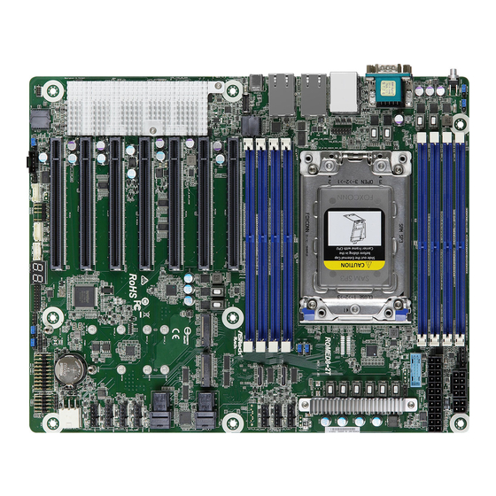
Motherboard Layout
Onboard LED Indicators
I/O Panel
Block Diagram
Chapter 2 Installation
Screw Holes
Pre-Installation Precautions
Installing the CPU
Installation of Memory Modules (DIMM)
Expansion Slots (PCI Express Slots)
Jumper Setup
Onboard Headers and Connectors
Dr. Debug
Unit Identification Purpose Led/Switch
Driver Installation Guide
Dual LAN and Teaming Operation Guide
(ROMED8-2T Only)
SSD Module Installation Guide
Chapter 3 UEFI Setup Utility
Introduction
UEFI Menu Bar
Navigation Keys
Main Screen
Advanced Screen
CPU Configuration
Chipset Configuration
Storage Configuration
ACPI Configuration
USB Configuration
Super IO Configuration
Serial Port Console Redirection
H/W Monitor
Amd Cbs
Amd Pbs
PSP Firmware Versions
Instant Flash
Server Mgmt
System Event Log
BMC Network Configuration
BMC Tools
Security
Key Management
Boot Screen
CSM Parameters
Event Logs
Exit Screen
Chapter 4 Software Support
Download and Install Operating System
Download and Install Software Drivers
Contact Information
Chapter 5 Troubleshooting
Troubleshooting Procedures
Technical Support Procedures
Returning Merchandise for Service
Advertisement
Quick Links
1
Installation of Memory Modules (DIMM)
Download this manual
ROMED8-2T
ROMED8-NL
ROMED8-2T/BCM
User Manual
Version 1.0
Published February 2022
Copyright©2022 ASRock Rack INC. All rights reserved.
Table of
Contents
Previous
Page
Next
Page
1
2
3
4
5
Advertisement
Table of Contents
Need help?
Do you have a question about the ROMED8-2T and is the answer not in the manual?
Ask a question
Questions and answers
Related Manuals for ASROCK ROMED8-2T
Motherboard ASROCK ROMED8-2T User Manual
Server/workstation motherboard (88 pages)
Computer Hardware ASROCK ROMED8-2T Quick Installation Manual
(2 pages)
Motherboard ASROCK ROMED4ID-2T User Manual
Server/workstation (76 pages)
Motherboard ASROCK ROME2D32GM-2T User Manual
(96 pages)
Motherboard ASROCK ROME2D32GM-2T User Manual
Server/workstation motherboard (99 pages)
Motherboard ASROCK ROMED8QM-2T User Manual
Server/workstation (88 pages)
Motherboard ASROCK ROMED8-NL User Manual
Server/workstation motherboard (91 pages)
Motherboard ASROCK GE PRO-HT R3.0 User Manual
(28 pages)
Motherboard ASROCK R-4130 Use And Care Manual
Pivot & flex with titanium technology (87 pages)
Motherboard ASROCK Z690M PG Riptide/D5 Manual
(180 pages)
Motherboard ASROCK Z690M PG RIPTIDE/D5 User Manual
(113 pages)
Motherboard ASROCK R0ME2D16-2T User Manual
(98 pages)
Motherboard ASROCK RM138 Series User Manual
Server/workstation motherboard (41 pages)
Motherboard ASROCK RM237-C622LM User Manual
Server/workstation motherboard (33 pages)
Motherboard ASROCK EPYC3451D4I2-2T User Manual
(74 pages)
Motherboard ASROCK X399D8A-2T User Manual
(84 pages)
This manual is also suitable for:
Romed8-nl
Romed8-2t/bcm
Table of Contents
Print
Rename the bookmark
Delete bookmark?
Delete from my manuals?
Login
Sign In
OR
Sign in with Facebook
Sign in with Google
Upload manual
Upload from disk
Upload from URL


Need help?
Do you have a question about the ROMED8-2T and is the answer not in the manual?
Questions and answers