Table of Contents
Advertisement
Quick Links
Advertisement
Table of Contents

Related Manuals for IFM Electronic efector300 SD6101


Summary of Contents for IFM Electronic efector300 SD6101
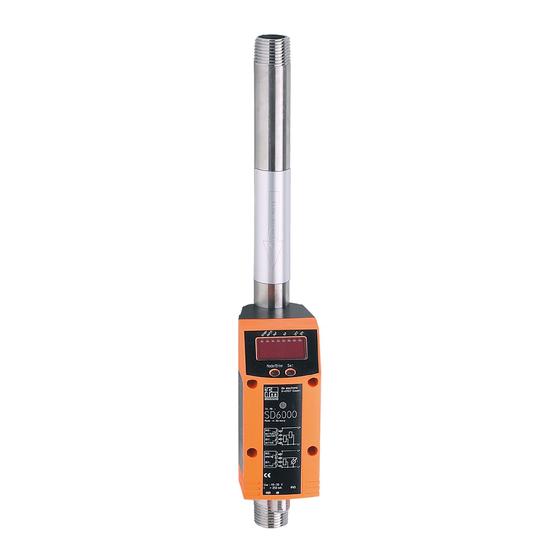
- Page 1 Operating instructions Compressed air meters SD6101...
-
Page 2: Table Of Contents
Contents 1 Preliminary note ���������������������������������������������������������������������������������������������������4 1�1 Symbols used ������������������������������������������������������������������������������������������������4 2 Safety instructions �����������������������������������������������������������������������������������������������4 3 Functions and features ����������������������������������������������������������������������������������������5 4 Function ���������������������������������������������������������������������������������������������������������������6 4�1 Process measured signals ����������������������������������������������������������������������������6 4�2 Volumetric flow monitoring �����������������������������������������������������������������������������6 4�3 Consumed quantity monitoring (totaliser function) ����������������������������������������6 4�3�1 Consumed quantity monitoring with pulse output ���������������������������������7 4�3�2 Consumed quantity monitoring with preset counter �����������������������������7 4�4 Temperature monitoring ���������������������������������������������������������������������������������7 4�5 Volumetric flow or temperature monitoring / switching function ���������������������8... - Page 3 10�1�3 Parameter setting tools ���������������������������������������������������������������������20 10�2 Parameter setting in general ���������������������������������������������������������������������20 10�2�1 Change from menu level 1 to menu level 2: �������������������������������������21 10�2�2 Locking / unlocking ���������������������������������������������������������������������������21 10�2�3 Timeout ���������������������������������������������������������������������������������������������21 10�3 Settings for consumed quantity monitoring �����������������������������������������������21 10�3�1 Configure limit value monitoring with OUT1 �������������������������������������21 10�3�2 Configure limit value monitoring with OUT2 �������������������������������������22 10�3�3 Configure analogue value for volumetric flow �����������������������������������22 10�4 Settings for consumed quantity monitoring �����������������������������������������������22...
-
Page 4: Preliminary Note
11�5 General operating conditions ���������������������������������������������������������������������29 12 Technical data and scale drawing ��������������������������������������������������������������������29 13 Factory setting �������������������������������������������������������������������������������������������������30 1 Preliminary note 1.1 Symbols used ► Instructions > Reaction, result […] Designation of keys, buttons or indications → Cross-reference Important note Non-compliance can result in malfunction or interference� Information Supplementary note�... -
Page 5: Functions And Features
liability for consequences of misuse by the operator� Improper installation and use of the devices results in a loss of the warranty claims� • Correct operation and compliance with the measurement accuracy can only be ensured if the environmental conditions specified in the technical data are adhered to�... -
Page 6: Function
4 Function 4.1 Process measured signals The unit displays the current process values� It generates 2 output signals according to the parameter setting� OUT1: 4 selection options Parameter setting - Switching signal for volumetric flow quantity limit value → 10.3.1 - or switching signal for flow velocity limit value → 10.3.1 - or pulse signal for quantity meter → 10.4.1... -
Page 7: 4�3�1 Consumed Quantity Monitoring With Pulse Output
• In addition the value before the last reset is saved� This value can also be displayed� The meter saves the totalled consumed quantity every 10 minutes� After a power failure this value is available as the current meter reading� If a time-controlled reset is set, the elapsed time of the set reset interval is also saved�... -
Page 8: 4�5 Volumetric Flow Or Temperature Monitoring / Switching Function
4.5 Volumetric flow or temperature monitoring / switching function OUTx changes its switching status if it is above or below the set switching limits (SPx, rPx)� The following switching functions can be selected: 4.5.1 Hysteresis function Normally open: [OUx] = [Hno] Normally closed: [OUx] = [Hnc] First the set point (SPx) is set, then the reset point (rPx) with the requested... -
Page 9: 4�6 Volumetric Flow Or Temperature Monitoring / Analogue Function
4.6 Volumetric flow or temperature monitoring / analogue function -30% -20% 100% 120% 130% Characteristics of the analogue output according to the standard IEC 60947-5-7 1: Output current in mA 2: Operating area 3: Measuring range 4: Range between analogue start point and analogue end point 5: Error message [Err�] is displayed 6: Final value of the measuring range (VMR) 7: Error message [OL] is displayed (= overload) -
Page 10: 4�7 Set Standard Conditions Of The Volume Flow
4.7 Set standard conditions of the volume flow The unit is adjusted to a standard volume flow to DIN ISO 2533, i�e� volume flow at 14�69 psi, 59 °F and 0 % relative air humidity� The unit can be set to different standard conditions: • Via the menu item [rEF�P] the standard pressure is set, which serves as a refer- ence for the measured and display values for volumetric flow (→ 10.6.5). -
Page 11: Installation
5 Installation ► The rules and regulations for the installation and operation of com- pressed air equipment must be observed� 5.1 Installation location ► Install the unit downstream of the cold dryer� ► Install the unit near the load� ► If compressed air is fed into the main pipe through parallel pipes: mount the unit in the main pipe�... -
Page 12: 5�3 Installation Position
5.3 Installation position • Permitted installation positions: pipe length vertical, any position (fig� 1, 2); pipe length horizontal, unit vertical (fig� 3, 5), unit on side, pipe length left (fig� 4)� • Avoid the installation position in fig� 6 (unit on side, pipe length right)� If the flow rate is low, the specified measurement accuracy cannot be adhered to�... -
Page 13: Electrical Connection
6 Electrical connection The unit must be connected by a qualified electrician� The national and international regulations for the installation of electrical equipment must be adhered to� Voltage supply according to EN 50178, SELV, PELV� ► Disconnect power� ► Connect the unit as follows: BK: black BN: brown OUT2... -
Page 14: Operating And Display Elements
7 Operating and display elements 1 to 8: Indicator LEDs • LEDs 1-6 = unit of the currently represented numerical value → 11.1 Reading the process value • LED 7 = switching status of output OUT2 / of input InD • LED 8 = switching status of output OUT1 9: Alphanumeric display, 4 digits • Current volumetric flow quantity (with setting [SELd] = [FLOW]) • Current flow velocity (with setting [SELd] = [FLOW]) • Meter reading of the totaliser (with setting SELd = TOTL) • Current medium temperature (with setting SELd = TEMP) -
Page 15: Menu
8 Menu 8.1 Main Menu scfm scfh °F Mode/Enter ↓ Extended functions... - Page 16 Explanation main menu SP1 / rP1 Upper / lower limit value for volumetric flow� ImPS Pulse value� Pulse repetition active (= pulse output) or not active ImPR (= preset counter function)� Output function for OUT1 (volumetric flow or consumed quantity): - Switching signal for the limit values�...
-
Page 17: 8�2 Extended Functions
8.2 Extended functions ↑ Main menu... - Page 18 Explanation extended functions HI / LO Maximum / minimum value memory for volumetric flow� FOU1 Status of output 1 in case of an internal fault� FOU2 Status of output 2 in case of an internal fault� dAP Measured value damping / damping constant in seconds� rTo Meter reset: manual reset / time-controlled reset�...
-
Page 19: Set
9 Set-up After power on and expiry of the power-on delay time of approx� 1 s the unit is in the Run mode (= normal operating mode)� It carries out its measurement and eval- uation functions and generates output signals according to the set parameters� • During the power-on delay time the outputs are switched as programmed: - ON with normally open function (Hno / Fno) - OFF with normally closed function (Hnc / Fnc)�... -
Page 20: 10�1�3 Parameter Setting Tools
10.1.3 Parameter setting tools You will find all necessary information about the required IO-Link hardware and software at www�ifm�com/gb/io-link� 10.2 Parameter setting in general 3 steps must be taken for each parameter setting: Select parameter ► Press [Mode/Enter] until the re- Mode/EnterSet quested parameter is displayed�... -
Page 21: 10�2�1 Change From Menu Level 1 To Menu Level 2
10.2.1 Change from menu level 1 to menu level 2: ► Press [Mode/Enter] until [EF] is dis- played� Mode/EnterSet ► Briefly press [Set]� > The first parameter of the submenu is Mode/EnterSet displayed (here: [HI])� 10.2.2 Locking / unlocking The unit can be locked electronically to prevent unintentional settings� ►... -
Page 22: 10�3�2 Configure Limit Value Monitoring With Out2
10.3.2 Configure limit value monitoring with OUT2 ► Select [Uni] and set the unit of measurement (→ 10.6.1). ► Select [SEL2] and set [FLOW]� ► Select [OU2] and set the switching function� - [Hno] = hysteresis function/normally open - [Hnc] = hysteresis function/normally closed - [Fno] = window function/normally open - [Fnc] = window function/normally closed ►... -
Page 23: 10�4�3 Setting The Pulse Value
10.4.3 Setting the pulse value ► Select [ImPS]� ► Press and hold [Set]� > The current numerical value flashes for 5 s, then one of the 4 digits becomes active and can be changed as below: 1� Briefly press [Set] >... -
Page 24: 10�4�5 Time-Controlled Counter-Reset
10.4.5 Time-controlled counter-reset ► Select [rTo]� ► Press [Set] until the requested value is displayed (intervals from 1 hour to 8 weeks)� ► Briefly press [Mode/Enter]� ► Press [Set] until [rES�T] is displayed� ► Briefly press [Mode/Enter]� > The counter is reset automatically with the value now set� 10.4.6 Deactivate meter reset ►... -
Page 25: 10�5�2 Configure Analogue Value For Temperature
10.5.2 Configure analogue value for temperature ► Select [SEL2] and set [TEMP]� ► Select [OU2] and set the function� - [I] = temperature-proportional current signal (4…20 mA) ► Select [ASP] and set the value at which the minimum value is provided� ►... -
Page 26: 10�6�4 Set Output Status In Fault Condition
10.6.4 Set output status in fault condition ► Select [FOU1] and set the value - [On] = output 1 switches ON in case of an error� - [OFF] = output 1 switches OFF in case of an error� > For both values ([ON] and [OFF]) the counter stops counting in case of a fault�... -
Page 27: 10�7 Service Functions
10.7 Service functions 10.7.1 Read min/max values for volumetric flow ► Select [HI] or [Lo], briefly press [Set]� [HI] = maximum value, [Lo] = minimum value Delete memory ► Select [HI] or [Lo]� ► Press and hold [Set] until [----] is displayed� ►... -
Page 28: Operation
11 Operation 11.1 Reading the process value The LEDs 1-6 signal which process value is currently displayed� The process value to be displayed as standard (temperature, flow velocity or me- ter reading of the totaliser) can be preset → 10.6.2 Configuration of the standard display)� A standard unit of measurement can be defined for the flow velocity (scfm or scfh or sfs → 10.6.1). -
Page 29: 11�3 Read Set Parameters
11.3 Read set parameters ► Press [Mode/Enter] until the requested parameter is displayed� ► Briefly press [Set]� > The unit displays the corresponding parameter value� > After about 15 s (from menu level 1) or 30 s (from menu level 2) it again dis- plays the parameter, then it returns to the Run mode�... - Page 30 13 Factory setting Factory setting User setting 20 % * 19.5 % * ImPS 0.02 ImPR 40 % * 39.5 % * ASP2 0 % * AEP2 100 % * FOU1 FOU2 scfh SELd FLOW SEL2 FLOW rEF.P 14.69 psi rEF.T 59 °F 0.25 % *...
Need help?
Do you have a question about the efector300 SD6101 and is the answer not in the manual?
Questions and answers