Table of Contents
Advertisement
Quick Links
Advertisement
Table of Contents

Related Manuals for IFM Electronic efector300 SD5000


Summary of Contents for IFM Electronic efector300 SD5000
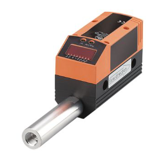
- Page 1 Operating instructions Compressed air meter SD5000...
-
Page 2: Table Of Contents
Contents 1 Preliminary note ���������������������������������������������������������������������������������������������������4 1�1 Symbols used ������������������������������������������������������������������������������������������������4 2 Safety instructions �����������������������������������������������������������������������������������������������4 3 Functions and features ����������������������������������������������������������������������������������������5 4 Function ���������������������������������������������������������������������������������������������������������������5 4�1 Processing of the measured signals ��������������������������������������������������������������5 4�2 Volumetric flow monitoring �����������������������������������������������������������������������������6 4�3 Consumed quantity monitoring (totalizer function) ����������������������������������������6 4�3�1 Consumed quantity monitoring with pulse output ���������������������������������6 4�3�2 Consumed quantity monitoring with preset counter �����������������������������6 4�4 Temperature monitoring ���������������������������������������������������������������������������������7... - Page 3 9�3�1 Settings for quantity monitoring via pulse output ��������������������������������18 9�3�2 Settings for quantity monitoring via the preset counter ����������������������19 9�3�3 Settings for program-controlled counter reset ������������������������������������19 9�3�4 Deactivation of the counter reset ��������������������������������������������������������19 9�3�5 Counter reset using an external signal �����������������������������������������������19 9�4 Settings for temperature monitoring ������������������������������������������������������������20 9�4�1 Settings for limit value monitoring with OUT2 �������������������������������������20 9�4�2 Setting the analogue value for temperature ���������������������������������������20...
-
Page 4: Preliminary Note
1 Preliminary note 1.1 Symbols used ► Instruction > Reaction, result […] Designation of pushbuttons, buttons or indications → Cross-reference Important note Non-compliance can result in malfunction or interference� Information Supplementary note� 2 Safety instructions • Please read this document prior to set-up of the unit� Ensure that the product is suitable for your application without any restrictions�... -
Page 5: Functions And Features
liability for consequences of misuse by the operator� Improper installation and use of the measurement devices results in a loss of the warranty claims� 3 Functions and features The unit monitors the standard volume flow of compressed air in industrial use� It detects the 4 process categories flow velocity, volumetric flow quantity, con- sumed quantity, medium temperature�... -
Page 6: 4�2 Volumetric Flow Monitoring
4.2 Volumetric flow monitoring The flow is monitored by a calorimetric measuring system, the measured signals are evaluated by the electronics� • 2 switching signals for volumetric flow limit values can be provided (output 1 and output 2). Switching functions → 4.5. • An analogue signal which is proportional to the volumetric flow (4���20 mA) can be provided on output 2. Analogue functions → 4.6. -
Page 7: 4�4 Temperature Monitoring
In this case the time-controlled totalizer reset is not carried out if [ImPS] = quantity X exceeded� - If the quantity x is not reached during the time t, the meter is automatically reset and counting starts again; output 1 does not switch� • Quantity monitoring not time-dependent�... -
Page 8: 4�6 Volumetric Flow Or Temperature Monitoring / Analogue Function
HY = hysteresis; FE = window 4.6 Volumetric flow or temperature monitoring / analogue function -30% -20% 100% 120% 130%... -
Page 9: 4�7 Setting Of The Standard Conditions Of The Volume Flow
Characteristics of the analogue output to the standard IEC 60947-5-7 1: Output current in mA 2: Operating area 3: Measuring range 4: Range between analogue start point and analogue end point 5: Error message [Err] is displayed 6: Final value of the measuring range (VMR) 7: Error message [OL] is displayed (= overload) 8: Analogue end point (AEP): determines at which measured value the output signal is 20 mA�... -
Page 10: Installation
5 Installation The rules and regulations for the installation and operation of compressed air equipment must be observed� 5.1 Installation location • Behind the cold dryer / near the load� • If compressed air is fed into the main pipe through parallel pipes, the unit should be mounted in the main pipe�... -
Page 11: 5�3 Installation Position
5.3 Installation position • Permitted installation positions: pipe length vertical, any position (fig� 1, 2); pipe length horizontal, unit vertical (fig� 3, 5), unit on side, pipe length left (fig� 4)� • Avoid the installation position in fig� 6 (unit on side, pipe length right)� If the flow rate is low, the specified measurement accuracy cannot be adhered to�... -
Page 12: Electrical Connection
6 Electrical connection The unit must be connected by a qualified electrician� The national and international regulations for the installation of electrical equipment must be adhered to� Voltage supply according to EN 50178, SELV, PELV� ► Disconnect power� ► Connect the unit as follows: OUT2/InD OUT1/IO-Link Pin 1... -
Page 13: Operating And Display Elements
7 Operating and display elements 1 2 3 4 5 6 7 8 Mode/Enter Set 1 to 8: Indicator LEDs - LED 1 (green) = current volumetric flow in standard litres / minute (Nl/min)� - LED 2 (green) =current volumetric flow in standard cubic metres / hour (Nm /h)�... -
Page 14: Menu
8 Menu 8.1 Menu structure Nl/min Nm/s °C = [Mode/Enter] / = [Set] • • Nm = current meter reading in Nm / Nm * = stored meter reading in Nm • The parameter values displayed in the form of numbers are factory settings or random examples�... -
Page 15: 8�2 Explanation Of The Menu
8.2 Explanation of the menu SP1/rP1 Upper / lower limit value for volumetric flow� ImPS Pulse value� Pulse repetition active (= pulse output) or not active ImPR (= preset counter function)� Output function for OUT1 (volumetric flow or consumed quantity): - Switching signal for the limit values: hysteresis function or window function, either normally open or normally closed�... -
Page 16: Parameter Setting
9 Parameter setting Parameters can be set before installation and set-up of the unit or during operation� If you change parameters during operation, the operating principle of the plant will be influenced� ► Ensure that there will be no malfunctions in your plant� Using an IO-Link capable parameter setting tool such as the FDT service program ifm Container the following options are available: - Reading current process values�... - Page 17 Setting of other parameters ► Start again with step 1� Finishing the parameter setting ► Press [Mode/Enter] several times until the current measured value is displayed or wait for 15 s (from menu level 1) or 30 s (from menu level 2)� >...
-
Page 18: 9�2 Settings For Volumetric Flow Monitoring
9.2 Settings for volumetric flow monitoring 9.2.1 Settings for limit value monitoring with OUT1 ► Select [Uni] and set the unit of measurement (→ 9.5.1). ► Select [OU1] and set the switching function� - [Hno] = hysteresis function/NO - [Hnc] = hysteresis function/NC - [Fno] = window function/NO - [Fnc] = window function/NC ►... -
Page 19: 9�3�2 Settings For Quantity Monitoring Via The Preset Counter
9.3.2 Settings for quantity monitoring via the preset counter ► Select [OU1] and set [ImP]� ► Select [ImPS] and set the volumetric flow quantity at which output 1 switches (→ 9.7). ► Select [ImPR] and set [no]� > Pulse repetition is not active� The output switches ON if the value set in [ImPS] is reached�... -
Page 20: 9�4 Settings For Temperature Monitoring
9.4 Settings for temperature monitoring 9.4.1 Settings for limit value monitoring with OUT2 ► Select [SEL2] and set [TEMP]� ► Select [OU2] and set the switching function� - [Hno] = hysteresis function/NO - [Hnc] = hysteresis function/NC - [Fno] = window function/NO - [Fnc] = window function/NC ►... -
Page 21: 9�5�3 Setting Of Measured Value Damping
9.5.3 Setting of measured value damping ► Select [dAP] and set the damping constant in seconds (t value 63 %)� 9.5.4 Setting of the error behaviour of the outputs ► Select [FOU1] and set the value - [On] = output 1 switches ON in case of a fault� - [OFF] = output 1 switches OFF in case of a fault�... -
Page 22: 9�6 Service Functions
9.6 Service functions 9.6.1 Reading of the min/max values for the volumetric flow ► Select [HI] or [LO], briefly press [Set]� [HI] = maximum value, [LO] = minimum value Delete memory ► Select [HI] or [LO]� ► Press [Set] and keep it pressed until [----] is displayed� ►... - Page 23 Setting operation: ► Set [OU1] to [ImP] (→ 9.3.2). ► Press [Mode/Enter] until [ImPS] is displayed� ► Press [Set] and keep it pressed� > The current numerical value flashes for 5 s, then one of the 4 digits becomes active (digit flashes, can be changed)� ►...
-
Page 24: Operation
► Wait 3 s (do The next digit on the right flashes (= becomes active)� not press any 8 1 2� 3 button)� No button pressed; after 3 s 8 1 2� 3 after 3 s 8 1 2� 3 after 3 s 8 1 2�... -
Page 25: 10�1 Reading Of Set Parameters
10.1 Reading of set parameters ► Press [Mode/Enter] until the requested parameter is displayed� ► Press [Set] briefly� > The unit displays the corresponding parameter value� After about 15 s (from menu level 1) or 30 s (from menu level 2) it again displays the parameter, then it returns to the Run mode�... -
Page 26: Factory Setting
12 Factory setting Factory setting User setting 3.00 2.92 ImPS 0.001 ImPR SP2 (FLOW) 6.00 rP2 (FLOW) 5.92 SP2 (TEMP) 24.0 rP2 (TEMP) 23.8 ASP (FLOW) 0.00 AEP (FLOW) 15.00 ASP (TEMP) AEP (TEMP) 60.0 DIn2 +EDG FOU1 FOU2 nm3h SELd FLOW SEL2...
Need help?
Do you have a question about the efector300 SD5000 and is the answer not in the manual?
Questions and answers