Table of Contents
Advertisement
Quick Links
Advertisement
Table of Contents

Related Manuals for IFM Electronic Efector 300 SI5002


Summary of Contents for IFM Electronic Efector 300 SI5002
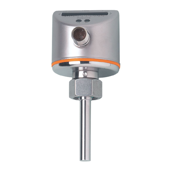
- Page 1 Operating instructions Flow monitors SI5002 SI5003 SI0521...
-
Page 2: Table Of Contents
Contents 1 Safety instructions ������������������������������������������������������������������������ 3 2 Functions and features ����������������������������������������������������������������� 4 2�1 Application area ������������������������������������������������������������������������ 4 2�2 Operating principle flow monitoring ������������������������������������������� 4 3 Installation ������������������������������������������������������������������������������������ 5 3�1 Installation location �������������������������������������������������������������������� 5 3�2 Sources of interference in the pipe system ������������������������������� 6 3�3�... -
Page 3: Safety Instructions
Preliminary note • An instruction is indicated by “►”: Example: ► Check whether the unit operates correctly. • A reaction to the action is indicated by ">": Example: > LED 9 lights. 1 Safety instructions • Please read the product description prior to set-up of the unit� Ensure that the product is suitable for your application without any restrictions� • The unit conforms to the relevant regulations and EC directives� • Improper or non-intended use may lead to malfunctions of the unit or to un- wanted effects in your application�... -
Page 4: Functions And Features
2 Functions and features 2.1 Application area The unit monitors the flow of liquid and gaseous media� 2.2 Operating principle flow monitoring • The unit detects the flow speed to the calorimetric measuring principle and switches the outputs S1 and S2: - Output S1 closed if flow ≥ SP1, output S1 open if flow < SP1. - Output S2 closed if flow ≥ SP2, output S2 open if flow < SP2 This applies to the unit on delivery: output = normally open. In case of need you can change the outputs to normally closed (→ 7.2). It then applies: output open if flow ≥ SP1 / SP2�... -
Page 5: Installation
3 Installation Using process adapters the unit can be adapted to different process connections� • Adapters have to be ordered separately as accessories� A correct fit of the unit and ingress resistance of the connection are only ensured using ifm adapters� • For small flow rates ifm adapter blocks are available�... -
Page 6: 3�2 Sources Of Interference In The Pipe System
3.2 Sources of interference in the pipe system Components integrated in the pipes, bends, valves, reductions, etc� lead to turbu- lence of the medium� This affects the function of the unit� Recommendation: Adhere to the distances between sensor and sources of interference: 5...10 x D 3...5 x D Flow High Flow High... -
Page 7: Electrical Connection
4 Electrical connection The unit must be connected by a qualified electrician� The national and international regulations for the installation of electrical equipment must be adhered to� Voltage supply to EN 50178, SELV, PELV� ► Disconnect power. ► Connect the unit as follows: 1 BN 1 BN 4 BK 4 BK... -
Page 8: Set-Up And Settings For Water
6 Set-up and settings for water (For media other than water → 7.1: Low flow adjustment). ► Switch on the supply voltage� > All LEDs light and go out again step by step. During this time the outputs are closed (if configured as normally open)� The unit is in the operating mode� ► Let the normal flow circulate in the installation� ► Check the display and determine further actions� The factory setting is suitable for the applica- Flow High... -
Page 9: 6�2 Change Switch Point Sp1
6.2 Change switch point SP1 ► Briefly press the pushbutton � > The SP1-LED flashes red, the SP2-LED lights red. ► Press the pushbutton as often as required� Each press of the push- button shifts the LED by one position in the indicated direction. Note: If no pushbutton is pressed for 2 s, the unit returns to the operating mode with the newly set value� 6.3 Change switch point SP2 ► Briefly press the pushbutton � > The SP2-LED flashes red, the SP1-LED lights red. ►... -
Page 10: 7�3 Restore The Factory Setting (Reset)
> After approx. 15 s LEDs 0...4 flash orange. ► Release the pushbutton� The outputs are changed to normally closed operation For a new changeover repeat the operation� 7.3 Restore the factory setting (reset) ► Press the pushbutton for at least 15 s� > LED 9 lights, after approx. 5 s it flashes. > After approx. 15 s LEDs 0...9 flash orange. ►... -
Page 11: Operation
9 Operation After every power on all LEDs light and go out again step by step (during this time the outputs are closed if configured as normally open)� The unit is then ready for operation� In case of power failure or interruption all settings remain� Operating indicators Green LED bar: Current flow within the representa- tion range� Indication of the switch points (SP1 / SP2): 0 1 2 3 4 5 6 7 8 9 - LED orange: output closed. -
Page 12: Scale Drawing And Technical Data
11 Scale drawing and technical data → www.ifm.com More information at www�ifm�com...
Need help?
Do you have a question about the Efector 300 SI5002 and is the answer not in the manual?
Questions and answers