
Related Manuals for Telex Audiocom US-2002


Summary of Contents for Telex Audiocom US-2002
- Page 1 User Instructions US-2002 Intercom User Station ® 9350-7748-000 Rev C 09/2009...
- Page 2 ROPRIETARY OTICE HIPPING TO THE ANUFACTURER The product information and design disclosed herein were originated by All shipments of product should be made via UPS Ground, prepaid (you and are the property of Bosch Security Systems, Inc. Bosch reserves all may request from Factory Service a different shipment method).
-
Page 3: Table Of Contents
Table Contents INTRODUCTION ......................................3 What’s New with the US-2002 ..................................3 Description ........................................3 Features ......................................... 4 Reference Descriptions ....................................5 INSTALLATION ......................................7 Unpacking ........................................7 Configuration Pre-check ....................................7 Headset Microphone Type Selection Dip Switch ............................9 Mic Kill Send Enable DIP Switch ................................. -
Page 5: Introduction
Description The US-2002 Intercom User Station is designed for stationary use by personnel who may require selective access to two or more intercom channels. It can be rack mounted or used as a desktop station. For rack mounting, optional hardware is required. -
Page 6: Features
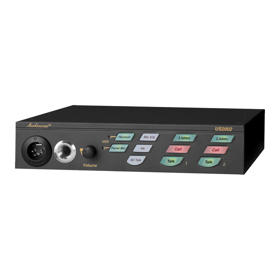
Features US-2002 Reference View (See “Reference Descriptions” on page 5.) FIGURE 1. -
Page 7: Reference Descriptions
Accepts headset with monaural headphones and either balanced or unbalanced dynamic microphones. Panel Mic/Electret Mic Headset Connector - Accepts an electret gooseneck microphone, such as the Telex Model MCP-90-XX. The Model MCP-90 series panel mic connector is a 1/4” stereo plug, with a threaded shaft for easy installation. -
Page 9: Installation
Termination plug for special applications (Figure 13 on page 24) Configuration Pre-check Before connecting the US-2002 ensure it is properly configured for your intended usage. Figure 2 on page 8 shows the configuration jumpers and switches locations. To access internal switches and jumpers, do the following: Remove one (1) screw from the top cover. - Page 10 Locations of Configuration Jumpers and Switches FIGURE 2. Configuration Switch Settings TABLE 1. SWITCH NUMBER DESCRIPTION SETTINGS DEFAULT SETTINGS DIP Switch SW1 (Internal) On: Unbalanced SW1-1 Headset microphone type Off: Balanced (typical) On: Enabled SW1-2 Call signal send, channel 1 Off: Disabled On: Enabled SW1-3...
-
Page 11: Headset Microphone Type Selection Dip Switch
Mic Kill Send Enable DIP Switch The US-2002 can generate an inaudible signal that turns off the microphones on all intercom stations on a channel (for stations that detect this signal). This feature is useful, for example, when an unattended microphone has been left on and is causing unnecessary noise on a channel. -
Page 12: Program Interrupt Dip Switches
Program Interrupt DIP Switches If you plan to use the external program sources with the US-2002, you have a choice of whether or not you want the program audio to shut off on the intercom channel while you are talking. -
Page 13: Balanced / Unbalanced Switch (Sw2)
See “External Program Input and PA Output” on page 13. Additionally, all program signals can be routed directly to the US-2002 speaker or headset. This lets the US-2002 operator hear the program inputs even if they are not being routed to the intercom channels. -
Page 14: Mounting Configurations
Mounting Configurations The US-2002 can be used on a desktop, or it can be rack mounted. For desktop use, install the four (4) rubber feet supplied with the US-2002. For rack mounting, use optional Audiocom RMK Rack Mount Kits (Figure 3). -
Page 15: Connections
Central Master Station vs. Remote Station The US-2002 can be used in a variety of configurations as a speaker station or as a headset station. Additionally, it can be used as a central master station or as a remote station. When used as a central master station, the US-2002 is placed in the same location as the system power supplies, and if an SPS2001 power supply is used, the US-2002 can take advantage of the SPS2001 built-in speaker for speaker output. - Page 16 Shielded patch cable, stereo miniplug to stereo miniplug. NOTE: Available at most electronic stores. Shielded audio cable. Must have male 3-pin XLR connector at one end for connection to the XP-USPG or XP-4PGM program inputs. Pin out for program inputs is as follows: Pin 1: common Pin 2: + program input Pin 3: - program input...
- Page 17 Combine/Isolate switch is set to the Isolate position. With this setting, the two (2) intercom channels are completely separated. The amplified speaker in the SPS2001 is used as the speaker output for the US-2002, and the US-2002 dip switches are set to monaural operation so that both intercom channels are heard in the speaker.
- Page 18 FIGURE 5. The configuration, shown in Figure 5, is suitable for smaller intercom systems when you want to operate the US-2002 as a master speaker station, with a separate speaker for each intercom channel. Make sure the US-2002 internal dip switches are set for binaural speaker operation as described on page 10.
- Page 19 FIGURE 6. The configuration, shown in Figure 6, is suitable for smaller intercom systems when you want to operate the US-2002 as a master headset station. In this configuration, the PS2001L Combine/Isolate switch is set to the Isolate position. With this setting, the 2 intercom channels are completely separated.
- Page 20 SPS2001 are combined on intercom channel 1 and all intercom stations connected to the PS-2001L are combined on channel 2. The amplified speaker in the SPS-2001 is used as the speaker output for the US-2002 and the US-2002 dip switches are set for monaural operation (default setting) so that both intercom channels are heard in the speaker.
- Page 21 FIGURE 8. The configuration, shown in Figure 8, is suitable for large intercom system when you want to operate the US-2002 as a master speaker station, with a separate speaker for each intercom channel. In this configuration, the SPS2001 Combine/Isolate switches are set to the Combine position.
- Page 22 PS2001L are combined on channel 2. Typically, a headset is connected to the front panel of the US- 2002, and the US-2002 dip switches are set to monaural operation (default setting) so that both intercom channels are heard in the monaural headphones (binaural headphone operation is not supported).
- Page 23 US-2002, the US-2002 automatically disconnects from system power. This allows more system power for belt packs and other intercom stations. Also, when the US-2002 is powered by a PA-KP, it can be operated over a greater distance as a remote...
- Page 24 SPK-2000, but is optional for the US-2002. When a PA-KP is connected to the US-2002, the US-2002 automatically disconnects from system power. This allows more system power for belt packs and other intercom stations. Also, when the US-2002 is powered by a PA-KP, it can be operated over a greater distance as a remote station.
- Page 25 Make sure the internal DIP switches are set for binaural speaker operation as described on “Monaural or Binaural Operation DIP Switches” on page 10. As in the previous example, a PA-KP local power supply is required for each SPK2000 speaker, but is optional for the US-2002. NOTE:...
- Page 26 The configuration, shown in Figure 13, shows all the components are locally powered using PA-KP local power supplies. Note, the use of one (1) termination plug in each intercom channel. (One (1) termination plug is supplied with each US-2002.) Only one (1) termination plug should be installed per channel. Typically, they are installed at the first intercom station in the chain.
- Page 27 13, for connector pin-out.) However, a more convenient method is to use an XP- USPG Breakout Panel as shown. The XP-USPG lets you use standard, 3-pin XLR audio cables to connect audio sources. The XP-USPG also interfaces the PA jack of the US-2002 to a standard, 3-pin XLR audio cable. NOTE:...
- Page 28 Audiocom Intercom Cables FIGURE 15.
-
Page 29: Operation
Power-Up Check When power is first applied to the US-2002, it performs a power-up reset, in which the front panel indicators cycles through all of the possible colors and then turn off. This verifies the general operation of the intercom station and indicators. The US-2002 also reads the settings of all DIP switches at this time and configures itself accordingly. -
Page 30: Sidetone Adjustment
Sidetone Adjustment The US-2002 uses full-duplex audio, the same as a conventional telephone line, in which the talk and listen audio are sent and received on the same line. Thus, when you talk on a channel, you also hear your own voice back in the speaker or headphones. -
Page 31: Voice-Activated Microphone Setup
Mic Kill indicator is not lit. programming mode– the Mic Kill indicator is continuously lit. To return the US-2002 to normal operation if it has been left in programming mode, do the following: > Tap the Mic Kill key. -
Page 32: Receiving Calls
Receiving Calls When there is an incoming call signal on a channel, the call indicator for that channel blinks red. There is a beep tone if the beep feature has been activated (see “Incoming Call Beep On/Off” on page 32). To receive a call, do the following: If you are using a dynamic-mic headset, tap the headset key to turn the mic on If you are using a panel-mounted microphone or an electret-mic headset, tap the panel mic key to turn the mic on. -
Page 33: Public Address
Public Address If the PA (Public Address) output on the back panel of the US-2002 is connected to a public address system., you can talk on the public address system. To use the PA system, do the following: If you are using manual microphone activation, verify the proper microphone switch is turned on (either headset or panel mic). -
Page 34: Using Voice-Activated Microphone (Vox)
The Mic Kill key lights green to indicate the intercom station is in programming mode. Tap either call key on the US-2002 to turn the beep feature on or off. Tap the Mic Kill key to return to normal operation. -
Page 35: Specifications
Connector Type: DB9F Specifications Pin 1 - Ground General Pin 2 - Program 1 input low Pin 3 - Program 2 input low Power Requirements: Pin 4 - NC Phantom Power: 24VDC nominal (12 to 30 VDC), Pin 5 - NC 65 to 150mA Pin 6 - Program 1 input high Local Power: 12 to 15VDC, 65 to 150mA... - Page 36 Connector Type: one XLR-3M and XLR-3F pair, Panel Microphone Amplifier wired in parallel, for each channel. Voltage Gains: Pin 1 - Common Mic to CHN; 25 ±3dB, before limiting Pin 2 - +24VDC input Mic to Headphone; adjustable, 45dB ±10% Pin 3 - Intercom audio high maximum, into 150 Ohms Mic to PA;...
-
Page 37: Quick Reference
Quick Reference Quick Reference TABLE 3. Reset US-2002 Press All Talk and Listen 1 Reset ES-4000A Press All Talk and Listen 5 Test signal on Press All Talk and PA, then tap Call Test signal off Tap Call, then tap any other key...
Need help?
Do you have a question about the Audiocom US-2002 and is the answer not in the manual?
Questions and answers