Table of Contents
Advertisement
Quick Links
Download this manual
See also:
Instructions for Using
Advertisement
Table of Contents

Subscribe to Our Youtube Channel
Related Manuals for Telex Audiocom US-2002


Summary of Contents for Telex Audiocom US-2002
- Page 1 User Instructions US-2002 Intercom User Station ® 9350-7748-000 Rev B 05/2006...
- Page 2 OTICE The product information and design disclosed herein were originated by and are the property of Telex Communications, Inc. Telex reserves all patent, proprietary design, manufacturing, reproduction, use and sales rights thereto, and to any article disclosed therein, except to the extent rights are expressly granted to others.
-
Page 3: Table Of Contents
TABLE CONTENTS Chapter 1 Introduction ...3 What’s New with the US2002 ...3 Description ...3 Features ...4 Chapter 2 Installation ...7 Unpacking ...7 Configuration Pre-check ...7 Headset Microphone Type Selection Dip Switch ...8 Mic Kill Send Enable DIP Switch ...8 Program Interrupt DIP Switches ...9 Monaural or Binaural Operation DIP Switches ...9 For Monaural operation with headphones or one speaker (factory default): ...9 For binaural operation with 2 speakers: ...9... - Page 4 TABLE CONTENTS...
-
Page 5: Chapter 1 Introduction
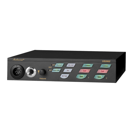
Updated gooseneck mic plug connection from a pin connector to a stereo plug for easy installation. • The Telex model MCP-90-XX microphone replaces the EGM-12N and EGM-18N microphone. Description The US2002 Intercom User Station is designed for stationary use by personnel who may require selective access to two or more intercom channels. -
Page 6: Features
Dynamic-Mic Headset Connector - Accepts headset with monaural headphones and either balanced or unbalanced dynamic microphones. Panel Mic / Electret Mic Headset Connector - Accepts an electret gooseneck microphone, such as the Telex Model MCP-90-XX. The Model MCP-90 series panel mic connector is a 1/4” stereo plug, with a threaded shaft for easy installation. - Page 7 Features Intercom Channel Connectors and Audiocom / Clear-Com channel for loop-through connection of multiple intercom stations. The selector switch sets the US2002 for compatibility with either Audiocom or Clear-Com channel connector pin-outs, channel power requirements, and call signaling requirements. 1. Brand names mentioned are the property of their respective companies. Selector Switch - Two connectors are provided for each...
- Page 8 Introduction...
-
Page 9: Chapter 2 Installation
Unpacking The package contains the following items. Contact the shipper or your Audiocom dealer immediately if anything is damaged or missing. Detach and fill out the registration card and return it to Telex to properly register your US2002. Quantity Description... -
Page 10: Headset Microphone Type Selection Dip Switch
Installation Locations of Configuration Jumpers and FIGURE 2. Switches Configuration Switch Settings TABLE 1. SWITCH NUMBER DESCRIPTION SETTINGS DIP Switch SW1 (Internal) On: Unbalanced Headset SW1-1 Off: Balanced microphone type (typical) On: Enabled Call signal send, SW1-2 channel 1 Off: Disabled On: Enabled Call signal receive, SW1-3... -
Page 11: Program Interrupt Dip Switches
Program Interrupt DIP Switches Program Interrupt DIP Switches If you plan on using external program sources with the US2002, you have a choice of whether or not you want the program audio to shut OFF on the intercom channel while you are talking. By default, program audio does not interrupt during talk. You can change this as follows: For channel 1 program interrupt during talk, set SW1-7 to ON. -
Page 12: Direct Program Listen Enable / Disable Jumpers
Direct Program Listen Enable / Disable Jumpers Direct Program Listen Enable / Disable Jumpers By default, each US2002 program input can be heard by all intercom stations that are listening on the corresponding intercom channel. This includes the US2002. Program input routing to the intercom channels can be turned ON or OFF via the US2002 front panel programming. -
Page 13: Connections
The numbers below correspond to the cable number in the connection drawings on the following pages. 1-channel intercom cable. Sold separately. Use Telex “ME” cables, below. Or, build per Figure 15 on page 24. ME-25: 25’ (7.6 m) cable with Male and Female 3-pin XLR connectors. - Page 14 Installation Shielded patch cable, stereo miniplug to stereo miniplug. Customer local purchase: available at most electronic stores. Shielded audio cable. Must have male 3-pin XLR connector at one end for connection to the XP-USPG or XP-4PGM program inputs. Pin-out for program inputs is as follows: Pin 1: common Pin 2: + program input Pin 3: - program input...
- Page 15 US2002 Monaural Master Speaker Station Configuration with 1 Power Supply. This is a good FIGURE 4. configuration for a smaller intercom system when you want to operate the US2002 as a master speaker station, with one speaker to monitor both intercom channels. In this configuration, the SPS-2001 Combine/Isolate switch is set to the Isolate position.
- Page 16 1, and the SPK2000 is used for channel 2. The PA-KP local power supply is optional. When a PA-KP is connected, the US2002 automatically disconnects from system power that is supplied by the SPS2001. Since the US2002 is not drawing power from the intercom system, more system power is available for additional belt packs, etc. NOTE: For further...
- Page 17 The PA-KP local power supply is optional. When a PA-KP is connected, the US2002 automatically disconnects from system power that is supplied by the PS2001L. Since the US2002 is not drawing power from the intercom system, more system power is available for additional belt packs, etc. NOTE: For further...
- Page 18 (default setting) so that both intercom channels are heard in the speaker. The PA-KP local power supply is optional. When a PA-KP is connected, the US2002 automatically disconnects from system power. Since the US2002 is not drawing power from the intercom system, more system power is available for additional belt packs, etc. NOTE: For further...
- Page 19 FIGURE 8. large intercom system when you want to operate the US2002 as a master speaker station, with a separate speaker for each intercom channel. In this configuration, the SPS2001 Combine / Isolate switches are set to the Combine position. With this setting, all intercom stations connected to the one SPS2001 are combined on intercom channel 1 and all intercom stations connected to the other SPS2001 are combined on channel 2.
- Page 20 Installation US2002 Headset Station Configuration with 2 Power Supplies. In this configuration, the PS2001L FIGURE 9. Combine/Isolate switches are set to the Combine position. With this setting all intercom stations connected to the one PS2001L are combined on intercom channel 1 and all intercom stations connected to the other PS2001L are combined on channel 2.
- Page 21 Cables Typical Remote Headset Station. In this example, the US2002 is not located near the system power FIGURE 10. supplies (SPS2001, PS2001L, etc.). The PA-KP local power supply is optional and can be used to power a single intercom station. When a PA-KP is connected to the US2002, the US2002 automatically disconnects from system power. This makes more system power available for belt packs and other intercom stations.
- Page 22 FIGURE 11. a Telex MCP-90-XX microphone and a SPK-2000 speaker are used instead of a headset. Make sure the intercom DIP switches are set for monaural speaker operation (default setting) as described on page 9. A PA-KP local power supply is required for the SPK-2000, but is optional for the US2002.
- Page 23 Cables NOTE: For further information about cables, see Figure 15 on page 24. Typical Remote Binaural Speaker Station. This example is similar to the one on the previous page, except FIGURE 12. that each channel is heard in a separate speaker. Make sure the internal DIP switches are set for binaural speaker operation as described on page 9.
- Page 24 Installation NOTE: For further information about cables, see Figure 15 on page 24. An example of all locally powered US2002 intercom stations. In this example, all components are locally FIGURE 13. powered using PA-KP local power supplies. Note, the use of one termination plug in each intercom channel. (One termination plug is supplied with each US2002.) Only one termination plug should be installed per channel.
- Page 25 Cables NOTE: For further information about cables, see Figure 15 on page 24. External Audio Input and PA Output. You can connect two audio sources to the Program Inputs FIGURE 14. connector: one for each channel. Audio sources can be directly connected with a user-supplied DB9M connector. (Refer to the program input connector specifications, located on page 11, for connector pin-out.) However, a more convenient method is to use an XP-USPG Breakout Panel as shown.
- Page 26 Installation Audiocom Intercom Cables FIGURE 15.
-
Page 27: Chapter 3 Operation
Power-Up Check Plug in any PA-KP local power supplies that are being used, and also turn on any system power supplies that are being used. When power is first applied to the US2002, it will perform a power-up reset, in which the front panel indicators will cycle through all of their possible colors and then turn OFF. - Page 28 Operation If you are using a speaker and microphone, or open-ear style headphones, adjust sidetone as follows: Simultaneously press the ALL Talk and PA keys to activate the test tone. Tap the channel 1 Call key to send the test tone on channel 1. Increase the volume until you can hear the test tone.
-
Page 29: Voice-Activated Microphone (Vox) Setup
Voice-Activated Microphone (Vox) Setup Voice-Activated Microphone (Vox) Setup If you are going to use vox, you must adjust the vox level for proper operation. If the vox level is too low, room noise will activate the microphone. If the vox level is too high, the microphone will not activate when you begin talking. Check and set the level as follows: If you are using a headset, tap the Headset key twice to turn ON headset vox. -
Page 30: Calling An Intercom Channel
Operation NOTE: When you tap the Headset key, or the Panel Mic key, or an any Talk or Listen key, it will lock in the ON position. You may then tap the key again to turn it OFF. For momentary activation, press and hold the key. It will remain ON as long as you hold it and it will turn OFF when you release it. -
Page 31: Turning The Program Inputs On And Off
Operation Turning the Program Inputs ON and OFF Insure that program inputs have been connected at the back panel and that the program sources are ON. Press and hold the Mic Kill key for about two seconds, then release it. It should now be glowing green to indicate the US2002 is in programming mode. -
Page 32: Specifications
Operation Specifications General Power Requirements: Phantom Power: 24VDC nominal (12 to 30 VDC), 65 to 150 mA Local Power: 12 to 15 VDC, 65 to 150 mA Dimensions: 1.75” (44.5 mm) high x 8.25” (209.5 mm) wide x 10.31” 261.9 mm deep Weight: Approximately 2lb. - Page 33 Specifications Frequency Response: 200Hz to 8kHz +1/-3dB Connector Type: RCA Phono Jack Tip: Speaker output high Sleeve: Common Expansion Input/Output Type: 2.0mm stereo phone jack Tip: Talk output Ring: Listen input Sleeve Common External Power Type: 2.0mm power jack Internal pin: positive (+) External shell: negative (-) Headphone Amplifier Voltage Gain:...
- Page 34 Operation Notes...
- Page 35 Notes Quick Reference TABLE 3. Reset US2002 Press All Talk and Listen 1 Reset ES4000A Press All Talk and Listen 5 Test signal ON Press All Talk and PA, then tap Call Test signal OFF Tap Call, then tap any other key Mic latched ON Tap Headset or Panel Mic (key is green) Mic latched OFF...
Need help?
Do you have a question about the Audiocom US-2002 and is the answer not in the manual?
Questions and answers