Table of Contents
Advertisement
Advertisement
Table of Contents

Related Manuals for Carestream DENTAL CS 8100 3D Series


Summary of Contents for Carestream DENTAL CS 8100 3D Series
- Page 1 Panoramic and 3D Modality Installation Guide for CS 8100 3D Family Including CS 8100 3D CS 8100 3D Access CS 8100 3D Select CS 8100SC 3D CS 8100SC 3D Access CS 8100SC 3D Select Panoramic and 3D Modality Installation Guide for CS 8100 3D Family_SM843_Ed10 1 ...
-
Page 2: Table Of Contents
Contents Notice ..........................4 Conventions in this Guide....................5 Functional Overview ......................6 Functional Overview..........................6 Mobile Components..........................7 General Functional Components......................8 Head and Chin Rest ..........................9 Positioning Panel ..........................10 X-ray Remote Control Overview ......................11 Positioning Accessories ........................ - Page 3 Running the Post-Installation Control ....................60 Fitting the Covers ..........................63 Maintenance ........................64 Panoramic and 3D Modality Installation Guide for CS 8100 3D Family_SM843_Ed10 3 ...
-
Page 4: Notice
The information contained in this guide may be subject to modification without notice, justification or notification to the persons concerned. No part of this guide may be reproduced without the express permission of Carestream Dental LLC. The US Federal law restricts this device to sale by or on the order of a physician. -
Page 5: Conventions In This Guide
Conventions in This Guide The following special messages emphasize information or indicate potential risk to persons or equipment: WARNING: Warns you to avoid injury to yourself or others by following the safety instructions precisely. CAUTION: Alerts you to a condition that might cause serious damage. IMPORTANT: Alerts you to a condition that might cause problems. -
Page 6: Functional Overview
Functional Overview The CS 8100 3D Family comprises: • CS 8100 3D: Panoramic modality and dental volumetric reconstruction modality, 3D focused teeth acquisition and 3D full upper and lower jaw acquisition. • CS 8100 3D Access: Panoramic modality and dental volumetric reconstruction modality, limited to 3D focused teeth acquisition. -
Page 7: Mobile Components
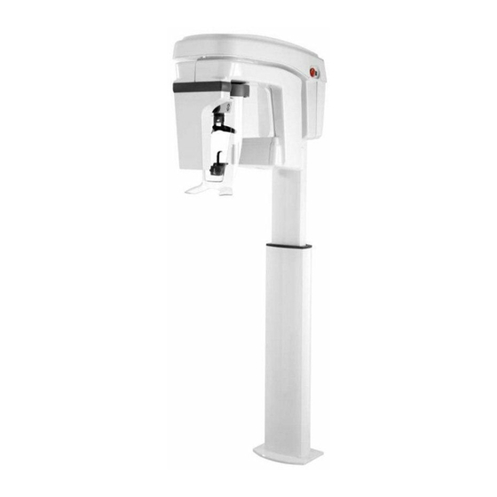
Mobile Components The following figure illustrates the general overview of CS 8100 3D. Figure 1 illustrates the up and down movement of the CS 8100 3D unit mobile component and the rotation and translation of the rotative arm. Figure 1 CS 8100 3D Unit Mobile Components Note: Patients can enter through either the left or right side of the unit. -
Page 8: General Functional Components
General Functional Components Figure 2 illustrates the general functional components of the CS 8100 3D unit. Figure 2 CS 8100 3D Unit Functional Components X-ray remote control Door safety switch Unit mains connecting terminal X-ray warning lamp RJ45 ethernet cable Computer hosting the imaging and the acquisition software Access panel Sensor Mounting bracket... -
Page 9: Head And Chin Rest
Head and Chin Rest Figure 3 illustrates the functional components of the CS 8100 3D head and chin rest. Figure 3 Head and Chin Rest Functional Components Positioning Panel Temple support adjustment knob Temple support Bite block support Chin rest Hand grips Head restraint strap ... -
Page 10: Positioning Panel
Positioning Panel The positioning panel is a console on the head and chin rest that enables you to correctly position and align a patient before you acquire an image. Figure 4 Unit Positioning Panel 1 Height Adjustment buttons: • Adjusts the height of the unit to the height of the patient. When the unit is not in use, places the rotative arm in a parallel position to the unit head, leaving more free space around the unit. -
Page 11: X-Ray Remote Control Overview
X-ray Remote Control Overview The X-ray remote control enables you to launch a radiological image acquisition via the exposure button from outside the X-ray room. You must press and hold the exposure button until the end of acquisition. Premature release of the exposure button interrupts the acquisition. -
Page 12: Positioning Accessories
Positioning Accessories The following accessories are used when positioning a patient using the unit. Table 1 Positioning Accessories Accessory Description Panoramic chin rest Sinus chin rest TMJ nose rest Standard bite block (x5) Frankfort guide bite block for panoramic (x3) Bite block for edentulous patients (x2) 3D bite block support Panoramic and 3D Modality Installation Guide for CS 8100 3D Family_SM843_Ed10... - Page 13 Accessory Description 3D bite block (x4) 3D molar bite block (x2) 3D child bite block (x2) 3rd Molar offset 3D bite block (x2) (for use with 5x5 MI and Mr FoV only) Temple support cone (for use with 3rd Molar offset 3D bite block only) Single use sheaths for bite block (500 pcs box) Single use sheaths for 3D bite block and Frankfort guide bite block (100 pcs box)
-
Page 14: Cs 8100 3D Family Packaging
CS 8100 3D Family Packaging Standard Packaging When unpacking the boxes, ensure that you received the following components. Table 2 Head Assembly Components Content Dimension Weight System column System head Head top cover Head and chin rest 755 (D) x 1600 (L) x 860 (H) mm ±... - Page 15 Content Dimension Weight 3D counterweight blocks Panoramic and 3D Modality Installation Guide for CS 8100 3D Family_SM843_Ed10 15 ...
-
Page 16: Box A Components
Box A Components Table 3 Column Assembly Components Component Description Column assembly Cable sheath Panoramic and 3D Modality Installation Guide for CS 8100 3D Family_SM843_Ed10 16 ... -
Page 17: Box B Components
Box B Components Table 4 Head Assembly Components Component Description System head Head top cover Panoramic and 3D Modality Installation Guide for CS 8100 3D Family_SM843_Ed10 17 ... -
Page 18: Box C Components
Box C Components Table 5 Head and Chin Rest Component Component Description Head and chin rest Panoramic and 3D Modality Installation Guide for CS 8100 3D Family_SM843_Ed10 18 ... -
Page 19: Box D Components
Box D Components Box D is divided into four compartments: • D1: Panoramic accessories kit • D2: 3D accessories kit • D3: Installation kit • D4: Documentation Panoramic and 3D Modality Installation Guide for CS 8100 3D Family_SM843_Ed10 19 ... -
Page 20: Compartment D1 Panoramic Accessories Kit
Compartment D1 Panoramic Accessories Kit Table 6 Panoramic Accessories Kit Component Description Panoramic chin rest Sinus chin rest TMJ nose rest Standard bite block (x5) Frankfort guide bite block for panoramic (x3) Bite block for edentulous patients (x2) 12 A - 5x20 - T fuse Panoramic and 3D Modality Installation Guide for CS 8100 3D Family_SM843_Ed10 20 ... - Page 21 Component Description Single use sheaths for bite block (500 pcs box) Panoramic and 3D Modality Installation Guide for CS 8100 3D Family_SM843_Ed10 21 ...
-
Page 22: Compartment D2 3D Accessories Kit
Compartment D2 3D Accessories Kit Table 7 3D Accessories Kit Component Description Single use sheaths for 3D bite block (100 pcs box) 3D bite block support 3D bite block (x4) 3D molar bite block (x2) 3D child bite block (x2) 3rd Molar offset 3D bite block (x2) (for use with 5x5 Ml and Mr FoV only) Temple support cone (for use with 3rd Molar offset 3D bite block only) -
Page 23: Compartment D3 Installation Kit
Compartment D3 Installation Kit Table 8 Installation Kit Component Description Screws Exposure switch Panoramic and 3D Modality Installation Guide for CS 8100 3D Family_SM843_Ed10 23 ... -
Page 24: Compartment D4 Documentation
Compartment D4 Documentation Table 9 Documentation Component Description User Guide Installation Guide Safety and Regulatory Guide DVD-ROM Panoramic and 3D Modality Installation Guide for CS 8100 3D Family_SM843_Ed10 24 ... -
Page 25: Box E Components
Box E Components Table 10 Column Accessories Component Description Column front cover Column rear cover Mounting bracket Angulated mounting bracket (option) Angulated mounting bracket cover (option) Panoramic and 3D Modality Installation Guide for CS 8100 3D Family_SM843_Ed10 25 ... -
Page 26: Box F Component
Box F Component Table 11 Counterweight Block WARNING: The counterweight is VERY HEAVY (15 kg). Ensure that you are protected from injury in case of accident. Component Description Counterweight block for CS 8100SC 3D and CS 8100 3D (upgradeable to scan ceph) Sensor counterweight block for CS 8100SC 3D and CS 8100 3D (upgradeable to scan ceph) Metal wedges for the CS 8100 3D (upgradeable to scan ceph) counterweight block ... -
Page 27: Site Preparation Before Installation
Site Preparation Before Installation IMPORTANT: Carefully check the following requirements for the X-ray room before you place a purchase order and before installation. Standard Compliance Install the unit in an X-ray room compliant with all official regulations applicable to protection against radiation. Environmental Requirements Check the following ambient operating condition requirements of the X-ray room before installing the system: •... -
Page 28: Unit Dimensions
Unit Dimensions Figure 6 Unit Dimensions The unit dimensions illustrated in Figure 6 are as follows: • Maximum height of the system: 2246 mm (88.5 in) • Chin rest height: minimum of 1062.5 mm (41.83 in) and maximum of 1712.5 mm (67.421 in) •... -
Page 29: Electrical Requirements
Electrical Requirements The unit operates at 100—240 V ~ 50/60 Hz. Operating Voltages of the Unit Nominal Voltage* Minimum Maximum Minimum Line Current (no load) 100—240 V ~ 50/60 Hz 90 V ~ 264 V ~ 20 A CAUTION: The power supply cable must be equipped with a connection box that ensures that it is not possible to disconnect the system from power supply without using tools. -
Page 30: Electrical Diagram Of The X-Ray Room And The System Connections
Electrical Diagram of the X-Ray Room and the System Connections Figure 7 Electrical Diagram of the X-ray Room and the System Connections General mains Differential circuit breaker Red-colored emergency stop push-button Red-colored emergency stop push-button Red warning lamp, power ON indicator System mains connecting terminal Panoramic and 3D Modality Installation Guide for CS 8100 3D Family_SM843_Ed10 30 ... - Page 31 Warning lamp (X-ray emission or ready state indicator) X-ray warning lamp connecting terminal Column connecting terminals X-ray remote control Door safety switch Mains outlet (for electric tools) Ethernet outlet (RJ45/1) Contactor Panoramic and 3D Modality Installation Guide for CS 8100 3D Family_SM843_Ed10 31 ...
-
Page 32: Electrical Installation Specifications
Electrical Installation Specifications A single-phase alternating current power supply is required. The electrical installation specifications must be as follows. Table 12 Electrical Installation Specifications Supply Voltage 200—240 V ~ 100—130 V ~ Frequency 50/60 Hz 50/60 Hz Electrical Supply 6 kW 6 kW ... -
Page 33: Recommended Wall Outlet Setup
Recommended Wall Outlet Setup We recommend that you install a vertical or horizontal wall outlet at the back of the column, below the mounting bracket. IMPORTANT: The top of the wall outlet must be no higher than 1000 mm (39.37”) from the floor). -
Page 34: X-Ray Room Requirements
X-ray Room Requirements IMPORTANT: Use an appropriate wall fixing system suitable for the type of wall construction (see the examples below). The following illustrations provide examples of wall types and fixations. Table 13 X-ray Room Requirements Room Components Minimum Requirement Comments Width of the door 75 cm (30 in) Panoramic and 3D Modality Installation Guide for CS 8100 3D Family_SM843_Ed10 34 ... - Page 35 Room Components Minimum Requirement Comments If needed, it is possible to lower the height of the Height of the ceiling 240 cm (95 in) system. It is the responsibility of the installer to choose an Withstanding an extraction force of Strength of the wall appropriate fixing system that withstands the 150 kPa at each point of attachment.
-
Page 36: Cs 8100 3D Minimum X-Ray Room Space Configuration
CS 8100 3D Minimum X-ray Room Space Configuration Figure 8 CS 8100 3D Minimum X-ray Room Space Configuration 3 Red-colored actuator emergency stop push-button 4 Red-colored actuator emergency stop push-button 5 Red warning lamp, power on indicator 6 Unit mains connecting terminal 7 Warning lamp (X-ray emission or ready state indicator) 7a X-ray warning lamp connecting terminal 9 X-ray remote control 10 Door safety switch 11 Mains outlet (for electrical tools) -
Page 37: Cs 8100Sc 3D Minimum X-Ray Room Space Configuration
CS 8100SC 3D Minimum X-ray Room Space Configuration If you want to upgrade the CS 8100 3D to a scan ceph module, the following figure provides the required minimum X- ray room space configuration: Figure 9 CS 8100SC 3D Minimum X-ray Room Space Configuration 3 Red-colored actuator emergency stop push-button 4 Red-colored actuator emergency stop push-button 5 Red warning lamp, power ON indicator 6 Unit mains connecting terminal... -
Page 38: Minimum Computer System Requirements
Minimum Computer System Requirements The CS 8100 3D Family minimum computer system requirements are available on the Carestream Dental technician website as a separate document with an edition number. Before you intervene on a client site, see the Carestream technician web site for the latest edition of the document. -
Page 39: Preparing The Unit Acquisition System
Preparing the Unit Acquisition System Installing the Ethernet Boards in the Computer Before installing the ethernet boards in the computer, check that the computer is: • Switched off • Disconnected from the mains power supply To install the ethernet boards in the computer, follow these steps: Install a 1 Gbits ethernet board (not supplied) in an unoccupied slot. - Page 40 Panoramic and 3D Modality Installation Guide for CS 8100 3D Family_SM843_Ed10 40 ...
-
Page 41: Installing The Imaging Software And Acquisition Interface
Installing the Imaging Software and Acquisition Interface Before installing the CS Imaging Software, check that: • The computer has all the necessary system requirements • You have the software DVD-ROM To install the CS Imaging Software, follow these steps: Insert the CS Imaging Software DVD-ROM (1/2) in the DVD-ROM drive and install the software. -
Page 42: Firewall Or Network Settings
Firewall or Network Settings You cannot access the Acquisition interface if you do not configure the firewall or network settings. To configure the firewall or network settings, follow these steps: On your desktop, double-click to open the CS Imaging Software. The Windows Security Alert dialog box is displayed. -
Page 43: Activating The 3D License
Activating the 3D License See the Carestream Dental technician website for information about how to activate your 3D license. Panoramic and 3D Modality Installation Guide for CS 8100 3D Family_SM843_Ed10 43 ... -
Page 44: Installing The Unit
Installing the Unit Tool Requirements The installer must supply the following tools: • Power drill • Screws and heavy duty fixings • Spirit level • Measuring tape • Cutter • Metric allen keys • Torx screwdriver • Metric spanners Note: The tool references mentioned in this guide are ISO tool references. -
Page 45: Installing The Column
Installing the Column IMPORTANT: Before installing the column we recommend that you install a wall outlet at the back of the column, below the mounting bracket (see Recommended Wall Outlet Setup). To install the column, follow these steps: Place the column on the floor in a horizontal position. - Page 46 Re-position the column against the wall and place the mounting bracket on the two bolts in the wall but do not fit the nuts. Mark the position of the fixing holes of the base of the column on the floor then move the column aside and drill the four holes. IMPORTANT: You must use the base plate (see Unit Dimensions) if the floor is inappropriate for technical or aesthetic reasons or if the client requests no floor...
- Page 47 IMPORTANT: If the floor is uneven, place the rubber mat under the base of the column before you fix the column to the floor. Insert and tighten the four screws that fix the base of the column to the floor. The screws are not provided. Insert and tighten the two nuts and washers to the wall mounting bracket Fit the column space fillers ...
-
Page 48: Installing The Head
Installing the Head To install the head, follow these steps: Remove the head from the box by pulling and sliding it carefully along the floor using the interior packaging base Remove the interior packaging , except for the packaging base. Remove the head cover ... - Page 49 WARNING: The positioning hook is ONLY intended for use as a TEMPORARY support while you screw the head to the column. DO NOT use it for a longer period than this. IMPORTANT: Make sure that you do not trap or tangle any cables. Insert and tighten the two upper screws and washers Push the box out of the way Undo the ribbon on top of the head.
- Page 50 Remove the pin blocking the rotative movement inside the unit head and place it carefully in its storage position , as you will need to use the pin later for calibration. IMPORTANT: Make sure that you do not lose the transport security pin. You need it for calibration, servicing, or possible future transportation. Turn the rotative arm by hand to have access to the screw hole located under the head of the unit. Insert the screw and washer and tighten it.
- Page 51 17. Connect the following cables: Table 14 Cable Connections This cable… Connects to… On the… Ethernet from the computer Ethernet coupler Next to the motor board Column resistive track CJ856 motor board Column actuator CJ856 motor board Warning lamp JZ036 PFC board Exposure switch JZ036 PFC board Panoramic and 3D Modality Installation Guide for CS 8100 3D Family_SM843_Ed10...
- Page 52 WARNING: The JZ036 PFC board is delivered with a 6.3 A - 5x20 - T fuse for the voltage rating of between 200—240 V. If your voltage rating is 100—130 V, remove the fuse and replace it with a 12 A - 5x20 - T fuse that is in the accessories kit.
-
Page 53: Installing The Cs 8100Sc 3D (Unit Serial Number Xximxxx)
Installing the CS 8100SC 3D (Unit Serial Number xxIMxxx) To install: Remove the rotative arm covers Remove the collimator packaging foam. Carefully pull and remove the plastic strip Mount the cephalometric counterweight block by placing the hole on the cephalometric counterweight block into the mounting peg on the rotative arm Insert and tighten the two screws Replace the rotative arm cover... - Page 54 Panoramic and 3D Modality Installation Guide for CS 8100 3D Family_SM843_Ed10 54 ...
-
Page 55: Installing The Cs 8100 3D Upgradeable To Scan Ceph (Unit Serial Number Xxinxxx)
Installing the CS 8100 3D Upgradeable to Scan Ceph (Unit Serial Number xxINxxx) To install: Remove the rotative arm covers and Remove the collimator packaging foam. Carefully pull and remove the plastic strip Place the two metal wedges, then insert and tighten the four screws Mount the cephalometric counterweight block by placing the hole on the cephalometric counterweight block into the mounting peg on the rotative arm Insert and tighten the two screws... - Page 56 Replace the other rotative arm cover Insert and tighten the two screws Place the sensor counterweight, insert and tighten the screws Replace the sensor cover Insert and tighten the two screws Panoramic and 3D Modality Installation Guide for CS 8100 3D Family_SM843_Ed10 56 ...
-
Page 57: Removing The Head
Removing the Head When removing the unit head you must follow the steps described in the installation procedure (steps 1-18) and carry out each installation step in reverse. The packaging provided with the unit that is used for the installation of the head must also be used when uninstalling the head. -
Page 58: Installing The Head And Chin Rest
Installing the Head and Chin Rest To install the head and chin rest, follow these steps: Hold the head and chin rest below the support bracket, then extend the CPA92-2 cable Slide off the plastic cover Push the CPA92-2 cable up through the support bracket and gently pull it out of the top of the head ... - Page 59 IMPORTANT: If you are installing the Scan Ceph module: • DO NOT carry out the post-installation procedures now. • Complete the Scan Ceph installation. See the Cephalometric Modality Installation Guide for CS 8100 Family and CS 8100 3D Family (SM988) for more information.
- Page 60 Running the Post-Installation Control Before running the Post-installation Control, check that: • The installation of the unit is complete • The installation of the imaging software is complete • You have the test tools • The unit and the computer is on •...
- Page 61 Click click here to login at the top of the window. The Service Tools Access window is displayed. Enter the Login and Password that was given to you at the CS 8100 3D training course and click Connect. IMPORTANT: The Login and Password are CASE SENSITIVE.
- Page 62 Click Post installation procedure. The Post Installation Procedure window is displayed. Read the two warnings that are displayed. Choose the appropriate answer from the list about the F1 fuse on the JZ036 PFC board. If you select No you cannot click Start in the next step. Click Start and follow the on-screen instructions.
- Page 63 Fitting the Covers Figure 10 CS 8100 3D (Upgradeable to Scan Ceph) covers To fit the covers: Slide the back column cover into the mounting channels and insert and tighten the two screws. IMPORTANT: Make sure that the ethernet cable and the exposure cable come out through the opening on one side of the back column cover. The power cable comes out from the opening on the other side.
- Page 64 Maintenance Annual Maintenance We recommend that a general inspection of the system should be carried out every year by an approved dental systems technician. The inspection should cover the following points: • Check the attachment points to the floor and the wall. •...
Need help?
Do you have a question about the CS 8100 3D Series and is the answer not in the manual?
Questions and answers
how can i order a new piece that supports the CBCT mouthpiece that slides over the two black prongs? One of the black prongs broke.