LIFE home integration RG1R UNI DL Instructions And Warnings For Installation, Use And Maintenance
Sl-pro montage team control unit for automations fitted with 230 v motors
Hide thumbs
Also See for RG1R UNI DL:

Subscribe to Our Youtube Channel
Related Manuals for LIFE home integration RG1R UNI DL


Summary of Contents for LIFE home integration RG1R UNI DL
- Page 1 RG1R DL RG1R UNI DL CONTROL UNIT FOR AUTOMATIONS FITTED WITH 230 V MOTORS INSTRUCTIONS AND WARNINGS FOR INSTALLATION, USE AND MAINTENANCE. VERSIONE 1DP093 - 12/2008...
-
Page 2: Standard Installation
STANDARD INSTALLATION Components and devices of a typical automation. ??????????????????????? 5RI122000 2AS3710000... - Page 3 AERIAL SKANT - SKANX RG58-50ohm COMMANDS COMMON N.C. STOP N.O. OPEN N.O. CLOSE N.O. STEP N.C. PHOTO1 N.C. PHOTO 24 Vac 3W max INDICATOR LIGHT EXIT 24 Vac 200 mA max 230 Vac 25W max FLASHING 230 Vac 40W max COUTESY LYGHT 230 Vac RG1 DL...
-
Page 4: Energy Saving
Energy Saving In order to save energy, we have introduced the function Energy Saving. 10 minutes after the end of programmation of the control board, the LED of the keyboard go out and it is no more possible to use the control board. To get the control board working again, switch it off and on. -
Page 5: Wiring And Connections
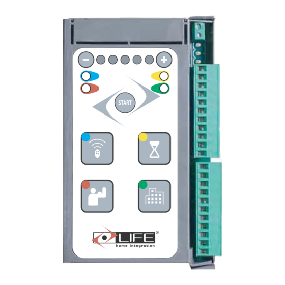
PROGRAMMING RADIO TRANSMITTERS PROGRAMMING RADIO TRANSMITTERS PHASE 3 TOTAL OPENING COMMAND TOTAL OPENING COMMAND AACKNOWLEDGMENT OF THE TOTAL OPENING RADIOCOMMAND • • Press the radio icon button (top left) once the Press the radio icon button (top left) once the left green led will light and the first (L to R) of left green led will light and the fi... - Page 6 1.1.1 Control unit wiring diagram of the lower part Terminals Description BLACK CABLE COMMON ELECTRONIC AND AUXILIARY POWER SUPPLY WHITE CABLE GEAR MOTOR RELEASE SWITCH ORANGE CABLE BLACK CABLE STOP PLATE and ENCODER RED CABLE COMMON CLOCKWISE ROTATION BLACK COMMON DARK BLUE 230Vac MOTOR OUTPUT GREEN...
- Page 7 List of electric cables The cables needed may vary depending on the installation and type and quantity of devices installed. The cables used in the installation must be IEC 60335 compliant. Connection Pos. Type of cable Electricity supply line 3x1,5 mm cable Power supply Cable supplied with Schuko socket...
- Page 8 RADIO CONTROL MANAGEMENT DELETING R ADIO CONTR OL TR ANS MITTER S The control unit is fitted with a built-in radio receiver with a 1 channel 1000-code memory, with a 433.92 MHz frequency with LIFE Rolling Code and Auto code encoding. Resetting an initialised radio control DELETING A S INGLE R ADIO TR ANS MITTER DELETING A S INGLE R ADIO TR ANS MITTER...
-
Page 9: Option Menu
3.1.2 Automatic reclosure Automatic reclosure is activated after a preset PAUSE TIME. In this mode, by pressing the ‘STEP’ key, the automation changes its motion according to the sequence 1 – OPEN 2 – PAUSE 3 – CLOSE 4 - PAUSE; for example, if the automation is opening and one selects the step command on the remote control, the automation stops in pause;... -
Page 10: Obstacle Detection
Functions 3.2.1 Courtesy light The courtesy light function switches a light on during any automation movement. The light remains on after the last manoeuvre for a 30-second period. 3.2.2 Deceleration in opening and closure The automation decelerates in the final stretches of opening and closureo. •... -
Page 11: Troubleshooting
TROUBLESHOOTING This chapter describes the most frequently encountered problems with the solutions for resolving them. In certain cases, it is explicitly envisaged that operations be performed by a professional fitter: these indications must be followed in order to avoid exposing oneself to serious risks. Malfunctions indicated on the control unit The malfunctions detected by the control unit are indicated through the lighting of the 5 LEDs on the display. -
Page 12: General Information
SAFETY INSTRUCTIONS AND WARNINGS chapter. With the aim of improving its products, LIFE home integration reserves the right to bring about alterations to them at any time, without giving prior notice. This document conforms to the state of the automation at which it is provided when released for sale. -
Page 13: First Usage
TESTING AND TRIAL RUN • The testing and trial run must be performed by a COMPETENT PERSON supervised and aided by a PROFESSIONAL FITTER. It is the responsibility of the person who tests and sets up the automation (of which the control unit is a part) to perform the checks required in accordance with the risks existing and to check conformity with the relevant legislation and standards, in particular with EN standard 12445, which governs the methods for performing trials on gate automations and EN standard 12453 that specifies the performance requisites concerning safety of use. -
Page 14: Routine Maintenance
MAINTENANCE 10.1 Maintenance instructions and warnings • Once the automation has been tested, the parameters set must not be altered. If further adjustments (e.g. alterations to the voltage value) are made, ALL THE CHECKS REQUIRED FOR TESTING AND COMPLIANCE WITH STANDARDS MUST BE REPEATED. •... -
Page 15: Declaration Of Conformity
Declaration of conformity under Directive 98/37/EC, appendix II, part B (Manufacturer’s Declaration of CE Conformity) LIFE Home Integration Via S.Pertini 3/5 31014 COLLE UMBERTO (TV) declares that the following product: RG1R DL control unit satisfies the essential requisites established in the following directives: •... - Page 16 Address: Via Sandro Pertini,3/5 31014 COLLE UMBERTO (TV) Italia Telephone: + 39 0438 388592 Telefax: + 39 0438 388593 http www.homelife.it e-mail: info@homelife.it...
Need help?
Do you have a question about the RG1R UNI DL and is the answer not in the manual?
Questions and answers