LIFE home integration RG1R DL S SUPRA MB 230 Vac Instruction And Advertising For Use And Maintenance
230 vac
Hide thumbs
Also See for RG1R DL S SUPRA MB 230 Vac:

Related Manuals for LIFE home integration RG1R DL S SUPRA MB 230 Vac


Summary of Contents for LIFE home integration RG1R DL S SUPRA MB 230 Vac
- Page 1 SUPRA MB 230Vac RG1R DL S ROAD BARRIER 230 V INS T R UC T ION AND ADV E R T IS ING F OR US E AND MAINT E NANC E Rev. 01 - 10/2014 LG...
-
Page 2: Technical Data
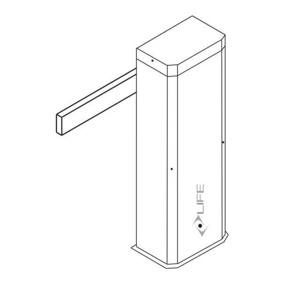
Dimensions - Weight 25x15 H100 30 Kg Control unit RG1R DL S Max 4 mt LIFE home integration reserves the right to make changes to technical characteristics at any time and without prior notice, without changing its intended use and function. - Page 3 Dis mantling of the barrier Manual releas e 180° ATTENTION...
- Page 4 F ixing on the ground with bas e s ole ( SUE 1 optional )
- Page 5 C los ure to LE F T 45° LEFT CLOSING LIMIT SWITCH OPENING LIMIT SWITCH WHITE BROWN GREEN GREEN 45° Unlocked pos ition boom SUM 1 Boom mt + protective rubber SUM 2 Boom mt + protective rubber...
- Page 6 C los ure to R IG HT 45° RIGHT CLOSING LIMIT SWITCH OPENING LIMIT SWITCH WHITE BROWN GREEN GREEN 45° Unlocked pos ition boom SUM 1 Boom mt + protective rubber SUM 2 Boom mt + protective rubber...
- Page 7 As s embly boom barrier mm 8 Mechanical stops adjus tment LEFT RIGHT...
-
Page 8: Wiring And Connections
WIRING AND CONNECTIONS • Before commencing wiring and connection work, read the SAFETY INSTRUCTIONS AND WARNINGS and INSTALLATION INSTRUCTIONS AND WARNINGS chaps carefully. • All wiring and connection operations must be carried out with the control unit disconnected from the electricity supply. If the disconnection device is not in view, display a sign reading: “ATTENTION: MAINTENANCE WORK IN PROGRESS”. -
Page 9: Indicator Leds
SKANT - SKANX AERIAL RG58-50ohm N.C. STOP N.O. OPEN N.O. CLOSE N.O. STEP N.C. PHOTO1 / THERMOSTAT N.C. PHOTO 24 Vac RADIO TRANSMITER CH2 24 Vac 3W max INDICATOR LIGHT EXIT 24 Vac 200 mA max 230 Vac 25W max FLASHING 230 Vac 40W max COUTESY LYGHT... -
Page 10: Programming The Control Unit
ATTENTION 230V 230V 2 PROGRAMMING THE CONTROL UNIT P H ASE 1 TOTAL RESET 230V 230V 230V PHASE 2 PROGRAMMING THE TRAVEL a) Press for 5 seconds, the 5 LEDs will light after start flashing. b) Press and the barrier starts rolling, if it opens press again the start button to invert the movement. - Page 11 RADIO CONTROL IDENTIFICATION The control unit is fitted with a built-in radio receiver with a 1000 code memory and 2 channels with a 433.92 MHz frequency with LIFE Rolling Code and Auto code encoding. PROGRAMMING RADIO TRANSMITTERS TOTAL OPENING a) Press The left green led will light b) Press (P1) Button on the transmitter once the top 5 led’s light.
- Page 12 Automatic closing Automatic closing is activated after a preset PAUSE TIME. In this mode by pressing the start button or radio transmitter the automation changes it motion as follows OPEN-PAUSE- CLOSE – PAUSE Press (top right) and the right green led switches will be on. If no leds are on the automatic closing is not enable Press the button to increase or the...
- Page 13 POWER This parameter adjusts opening an closing power of the barrier. Press the red LED (SX) switches on. Press to set the various power values. POWER LEDS ON Minimum MAXIMUM Wait 10 seconds or press again to quit. Obstacle detection The automation is fitted with an obstacle detection system: the automation inverts its movement when it strikes an obstacle duri n g the opening and closure phases.
-
Page 14: Connection Cables
Connection cables Fitters must make the connections of the 50 Hz 230 Vac electricity supply, and the various automation devices. Connections between the control unit, motor, encoder and transformer have already been performed by the Manufacturer. • Once the connections to the control unit have been made, the Fitter must use bands to join adjacent wires into groups of 2, 3 or 4 in order to prevent them coming away from the terminal board: bands must be attached as close as possible to the terminals, no more than 10mm away, taking care not to damage wire insulation. -
Page 15: First Usage
TESTING AND TRIAL RUN • The testing and trial run must be performed by a COMPETENT PERSON supervised and aided by a PROFESSIONAL FITTER. It is the responsibility of the person who tests and sets up the automation (of which the control unit is a part) to perform the checks required in accordance with the risks existing and to check conformity with the relevant legislation and standards, in particular with EN standard 12445, which governs the methods for performing trials on gate automations and EN standard 12453 that specifies the performance requisites concerning safety of use. -
Page 16: General Information
SAFETY INSTRUCTIONS AND WARNINGS chapter. With the aim of improving its products, LIFE home integration reserves the right to bring about alterations to them at any time, without giving prior notice. This document conforms to the state of the automation at which it is provided when released for sale. -
Page 17: Routine Maintenance
MAINTENANCE 14.1 Maintenance instructions and warnings • Once the automation has been tested, the parameters set must not be altered. If further adjustments (e.g. alterations to the voltage value) are made, ALL THE CHECKS REQUIRED FOR TESTING AND COMPLIANCE WITH STANDARDS MUST BE REPEATED. •... - Page 18 7 - Ricambi...
-
Page 19: Declaration Of Conformity
LIFE Home Integration Via S.Pertini 3/5 31014 COLLE UMBERTO (TV) declares that the following product: RG1R DL S SUPRA MB 230 Vac control unit satisfies the essential requisites established in the following directives: • Low voltage directive 73/23/EEC and subsequent amendments, •... - Page 20 Address: Via Sandro Pertini,3/5 31014 COLLE UMBERTO (TV) Italia Telephone: + 39 0438 388592 Telefax: + 39 0438 388593 www.homelife.it http e-mail: info@homelife.it...
Need help?
Do you have a question about the RG1R DL S SUPRA MB 230 Vac and is the answer not in the manual?
Questions and answers