Table of Contents
Advertisement
Quick Links
DESCRIPTION
Demo circuit DC2491A features the
ultralow noise and ultrahigh power supply rejection
ratio (PSRR) low dropout (LDO) regulator with program-
mable current limit.
DC2491A operates over an input voltage range of 3.8V
to 20V. The LT3045 delivers a maximum output current
of 500mA. In addition to featuring ultralow noise and
ultrahigh PSRR, the regulator offers programmable power
good functionality as well as programmable current limit.
Current monitoring is also achieved by sensing the ILIM
pin voltage.
Built-in protection includes reverse battery protection,
reverse current protection, internal current limit with
foldback, and thermal limit with hysteresis.
PERFORMANCE SUMMARY
PARAMETER
Input Voltage Range (V
)
IN
Input Voltage Range (V
)
IN
Output Voltage (V
)
OUT
Shutdown Input Current (I
)
IN
*The maximum input voltage for 500mA load current is set by the 60°C temperature rise of LT3045 on the demo circuit. Higher input voltage can be
reached if larger copper area or force-air cooling is applied. The output current is also limited by the differential of input and output voltage, please refer
the data sheet for details.
Ultrahigh PSRR RF LDO Regulator
LT
3045EDD, a 500mA,
®
Specifications are at T
CONDITIONS
I
= 150mA, V
= 3.3V
OUT
OUT
I
= 500mA, V
= 3.3V
OUT
OUT
V
= 5V, I
= 500mA
IN
OUT
JP1 = OFF , V
= 5V
IN
DEMO MANUAL DC2491A
20V, 500mA, Ultralow Noise
The LT3045 data sheet gives a complete description of the
device, operation and applications information. The data
sheet must be read in conjunction with this demo manual
for DC2491A. The LT3045EDD is assembled in a 10-lead
(3mm × 3mm) plastic DFN package with an exposed pad
on the bottom-side of the IC. Proper board layout is es-
sential for maximum thermal performance.
Design files for this circuit board are available at
http://www.linear.com/demo/DC2491A
L, LT, LTC, LTM, Linear Technology and the Linear logo are registered trademarks of Linear
Technology Corporation. All other trademarks are the property of their respective owners.
= 25°C
A
MIN
3.8V
3.8V
3.2V
LT3045EDD
TYP
MAX
20V
8.3V*
3.3V
3.4V
0.1μA
dc2491af
1
Advertisement
Table of Contents

Related Manuals for Linear Technology DC2491A


Summary of Contents for Linear Technology DC2491A
- Page 1 Built-in protection includes reverse battery protection, reverse current protection, internal current limit with L, LT, LTC, LTM, Linear Technology and the Linear logo are registered trademarks of Linear foldback, and thermal limit with hysteresis. Technology Corporation. All other trademarks are the property of their respective owners.
-
Page 2: Quick Start Procedure
DEMO MANUAL DC2491A QUICK START PROCEDURE DC2491A is easy to set up to evaluate the performance of 4. Turn the input power supply on and make sure the the LT3045EDD. Refer to Figure 1 for proper measurement voltage is between 3.8V and 20V. -
Page 3: Pcb Layout
PC board itself. While negligible for conventional low PSRR LDOs, LT3045’s ultrahigh PSRR requires careful attention to higher order parasitics in order to realize the full performance offered by the regulator. Figure 2. Layer 3 of DC2491A Figure 3. Bottom Layer of DC2491A dc2491af... - Page 4 Connections for Best Performance stability is eliminated. While the LT3045 is robust enough not to oscillate if the recommended layout is not followed, phase/gain margin and PSRR will degrade. Figure 5. Split Pads for C2 on Top Layer of DC2491A dc2491af...
-
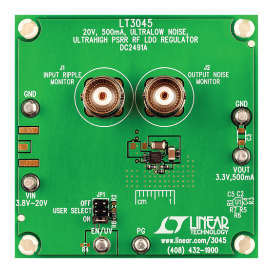
Page 5: Board Photo
DEMO MANUAL DC2491A BOARD PHOTO dc2491af... -
Page 6: Parts List
DEMO MANUAL DC2491A PARTS LIST ITEM REFERENCE PART DESCRIPTION MANUFACTURER/PART NUMBER Required Circuit Components CAP ., ALUM, 22µF, 35V, 5mm × 5.4mm SUN ELECTRONIC INDUSTRIES CORP ., 35CE22BSS C1, C4 CAP ., X7R, 4.7μF, 25V, 10% 1206 MURATA, GRM31CR71E475KA88L CAP ., X5R, 10μF, 25V, 10% 1206 MURATA, GJ831CR61E106KE83L RES., CHIP , 200k, 1/16W, 5% 0603... -
Page 7: Schematic Diagram
Information furnished by Linear Technology Corporation is believed to be accurate and reliable. However, no responsibility is assumed for its use. Linear Technology Corporation makes no representa- tion that the interconnection of its circuits as described herein will not infringe on existing patent rights. - Page 8 Linear Technology Corporation (LTC) provides the enclosed product(s) under the following AS IS conditions: This demonstration board (DEMO BOARD) kit being sold or provided by Linear Technology is intended for use for ENGINEERING DEVELOPMENT OR EVALUATION PURPOSES ONLY and is not provided by LTC for commercial use. As such, the DEMO BOARD herein may not be complete in terms of required design-, marketing-, and/or manufacturing-related protective considerations, including but not limited to product safety measures typically found in finished commercial goods.
Need help?
Do you have a question about the DC2491A and is the answer not in the manual?
Questions and answers